User’s Manual Models 4 36101/436102/436103/436104/436106/ 437101/437102/437103/437104/437106/ 437112/437118/437124 µR10000/µR20000 Communication Interface IM 04P01B01-17E 5th Edition
Thank you for purchasing the YOKOGAWA µR10000/µR20000 Recorder. This user’s manual describes the functions of the Ethernet interface and the RS422A/485 communication interface. To ensure correct use, please read this manual thoroughly before beginning operation. After reading the manual, keep it in a convenient location for quick reference whenever a question arises during operation. The following five manuals, including this one, are provided as manuals for the µR10000/ µR20000 Recorder.
Trademarks • All the brands or names of Yokogawa Electric’s products used in this manual are either trademarks or registered trademarks of Yokogawa Electric Corporation. • Microsoft, MS-DOS, Windows, Windows NT, and Windows XP are either registered trademarks or trademarks of Microsoft Corporation in the United States and/or other countries. • Adobe, Acrobat, and PostScript are trademarks of Adobe Systems incorporated.
How to Use This Manual Structure of the Manual This user’s manual consists of the following sections. Chapter 1 Overview of the Communication Functions Gives an overview of the communication functions. Chapter 2 Using the Ethernet Interface (/C7 Option) Explains the specifications of the Ethernet interface and how to use the interface. Using the RS-422A/485 Communication Interface (/C3 Option) Chapter 3 Explains the specifications of the RS-422A/485 communication interface and how to use the interface.
How to Use This Manual Conventions Used in This Manual • Unit • k: Denotes 1000. Example: 5 kg, 100 kHz • K: Denotes 1024. Example: 640 KB • Note The following markings are used in this manual. Improper handling or use can lead to injury to the user or damage to the instrument. This symbol appears on the instrument to indicate that the user must refer to the user’s manual for special instructions. The same symbol appears in the corresponding place in the user’s manual to identify those instructions.
Names of Parts and Basic Key Operations Display and Keys You use the panel keys and the display to configure the communication functions. For a description of other parts of the recorder, see section 3.1 in the Recorder User’s Manual. (The figure below is of the µR10000 Recorder.
Names of Parts and Basic Key Operations Basic Key Operations This section describes basic operations on the front panel keys to change various settings. • Execution Modes The recorder has the following execution modes. • Operation mode: A mode used to perform recording and monitoring. • Setting mode: A mode used to set the input range, alarms, chart speed, and other parameters. • Basic Setting mode: A mode used to set the basic specifications of functions with the recording operation stopped.
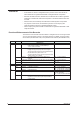
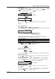
Names of Parts and Basic Key Operations • Entering Values Use the key or SHIFT + key to move the cursor. Use the key or SHIFT + key to change a digit value. You repeat these steps to enter the value. SHIFT key + key key A=000.000.000.000 8 7 key 6 A=000.005.000.000 4 3 2 SHIFT key + When you press the displayed. Target digit key key, the change is applied and the next setup item is • Entering Characters Use the key or SHIFT + key to move the cursor.
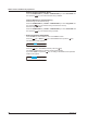
Names of Parts and Basic Key Operations Deleting an Entire Character String Press the CHARACTER key or SHIFT + CHARACTER key to show Clear DISP and then press the key. The entire character string is deleted. Copying & Pasting a Character String Show the copy source character string. Press the CHARACTER key or SHIFT + CHARACTER key to show Copy DISP and then press the key. The character string is saved to the memory. Show the copy destination.
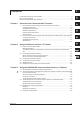
Contents 1 Functional Enhancement of the Recorder......................................................................................... ii How to Use This Manual................................................................................................................... iii Names of Parts and Basic Key Operations.......................................................................................v Chapter 1 Overview of the Communication Functions 1.1 1.2 Chapter 2 2.1 2.3 2.4 2.5 2.6 3.
Contents Chapter 4 Chapter 5 Commands 4.1 Command Syntax................................................................................................................. 4-1 Response.............................................................................................................................. 4-2 4.2 A List of Commands.............................................................................................................. 4-3 Execution Modes and User Levels..........................
Contents Appendix Appendix 1 Appendix 2 Appendix 3 Appendix 4 ASCII Character Codes..................................................................................... App-1 Output Flow of FIFO Data.................................................................................. App-2 Login Procedure................................................................................................. App-4 A List of Error Messages..............................................................................
Chapter 1 Overview of the Communication Functions 1.1 The recorder can be equipped with an optional Ethernet interface. For details on how to use the Ethernet interface, see chapter 2. Functional Construction The following figure shows the relationship between the communication function of the recorder and the Ethernet interface. Perform communication according to the respective protocol. * Protocol is a set of rules that two computers use to communicate via a communication line (or network).
1.1 Communication Functions Using the Ethernet Interface (/C7 Option) Maintenance/Test Server • Outputs Ethernet communication information such as connection information and network statistics from the recorder. • The commands that can be used Maintenance/Test commands. • Ethernet interface settings: Section 2.3 • Commands: Section 4.2 Instrument Information Server • Outputs the serial number, model name, and other information about the recorder connected via the Ethernet network.
1.1 Communication Functions Using the Ethernet Interface (/C7 Option) Other Functions 1 Only users that are registered in advance can access the Setting/Measurement and Maintenance/Test servers. • Users are identified by their user name and password. • You can register one administrator and six users.
1.2 Communication Functions Using the RS422A/485 Communication Interface (/C3 Option) The recorder can be equipped with an optional RS-422A/485 communication interface. For details on how to use the RS-422A/485 communication interface, see chapter 3. Functional Construction The following figure shows the relationship between the communication function of the recorder and the RS-422A/485 communication interface. Perform communication according to the respective protocol.
Chapter 2 2.1 Using the Ethernet Interface (/C7 Option) Ethernet Interface Specifications 1 Basic Specifications Transmission medium type Protocol 2 Specifications Conforms to IEEE 802.3 (Ethernet frames are of DIX specification) 10BASE-T TCP, IP, UDP, ICMP, and ARP 3 The Maximum Number of Simultaneous Connections and the Number of Simultaneous Use 4 The following table shows the maximum number of simultaneous connections, the number of simultaneous users, and the port numbers of the recorder.
2.2 Connecting the Ethernet Interface When Connecting Only the Recorder and a PC Connect the recorder and the PC via a HUB as in the following figure. µR10000/µR20000 Recorder 10BASE-T straight cable µR10000/µR20000 Recorder Hub PC 10BASE-T straight cable When Connecting to a Preexisting Network The following figure illustrates an example in which a recorder and a PC are connected to the network.
2.3 Configuring the Ethernet Interface 1 Set the host name and IP address of the recorder. You do not have to set the DNS (domain name system). Ethernet Host Host Local IP DNS End Domain Host name Domain name A M IP address Subnet mask DNS P DNS On/Off Suffix_P Domain suffix (primary) Server (primary) 3 G Default gateway S Server (secondary) 4 Suffix_S Domain suffix (secondary) 5 Procedure For a description of the basic setup operations, see “Basic Key Operations” on page vi.
2.3 Configuring the Ethernet Interface IP Address, Subnet Mask, and Default Gateway 1. Press the 2. Press the key to select Ethernet and then press the key. Basic=Ethernet key to select Local IP and then press the Ethernet=Local key. IP 3. Set the IP address of the recorder and then press the key. Key operations • Use the key to select the digit for entering a value. • Use the key to select the value you wish to enter. A= 4.
2.3 Configuring the Ethernet Interface 6. Set the primary domain suffix and then press the 1 key. Key operations • Use the key to select the digit for entering a character. • Use the CHARACTER key to select the character type. • Use the key to select the character you wish to enter. Suffix_P= 7. Set the secondary domain suffix and then press the key in the same fashion as in step 6. The DNS setting complete screen appears. Ethernet DNS Setting complete 5 8.
2.3 Configuring the Ethernet Interface • G (Default Gateway) • Set the IP address of the gateway (router, etc.) used to communicate with other networks. The default value is 0.0.0.0. • Set this value according to the system or the network to which the recorder belongs. In some cases, this setting may not be necessary. • Setting the DNS (Domain Name System) The DNS is a system that correlates the host name/domain name to the IP address.
2.4 Checking the Connection Status 1 The connection status of the Ethernet interface can be confirmed with the indicator that is located to the left of the Ethernet port on the recorder. Connection Status of the Ethernet Interface The Ethernet interface is electrically connected. Transmitting data. The Ethernet interface is not electrically connected.
2.5 Registering Users Users that can access the recorder via the Ethernet network must be registered. This function is called login function. Setup Items Ethernet Login Login Use/Not LoginSet Level Admin/User Register On/Off User User name Password End Procedure For a description of the basic operations, see “Basic Key Operations” on page vi. Entering Basic Setting Mode Hold down the MENU key for 3 seconds to display the Setting mode screen.
2.5 Registering Users 8. Set the user name and then press the 1 key. Key operations • Use the key to select the digit for entering a character. • Use the CHARACTER key to select the character type. • Use the key to select the character you wish to enter. User= 9. Set the password and then press the 3 key in the same fashion as in step 8. The setting complete screen appears. Password= 4 Ethernet login Setting complete To register other users, press the and 9.
2.5 Registering Users Note • • • The relationship between the login function and the user name that is used when accessing the recorder is as follows: • When the login function is set to “Use” • The registered user name and password can be used to login to the recorder. • The user level is the level that was specified when the user name was registered. • When the login function is set to “Not” • The user name “admin” can be used to login to the recorder as an administrator. Password is not necessary.
2.6 Setting the Communication Timeout and Keepalive 1 The communication timeout function and the keepalive function can be configured. 2 Ethernet Timeout Timeout End K.Alive Keep alive On/Off Using the Ethernet Interface (/C7 Option) Setup Items Duration Timeout time 3 On/Off Procedure 4 For a description of the basic operations, see “Basic Key Operations” on page vi. Entering Basic Setting Mode 5 Hold down the MENU key for 3 seconds to display the Setting mode screen.
2.6 Setting the Communication Timeout and Keepalive Keepalive 1. Press the key to select Ethernet and then press the 2. Press the key to select K.Alive and then press the Ethernet=K. key to select On and then press the The setting complete screen appears. Keep key. Alive 3. Press the key. Basic=Ethernet key. alive=On Keep alive Setting complete 4. Press the ESC key to return to the higher level menu.
Chapter 3 3.1 Using the RS-422A/485 Communication Interface (/C3 Option) RS-422A/485 Communication Interface Specifications 1 This section describes the RS-422A/485 communication interface specifications.
3.
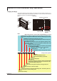
3.2 Terminal Arrangement and Signal Names and the Connection Procedure of the RS-422A/485 Communication Interface 1 WARNING To prevent the possibility of electric shock, connect the cables with the power turned OFF. 2 Note • 4 Connection Example with a Host Computer A connection can be made with a host computer having a RS-232, RS-422A, or RS-485 port. • In the case of RS-232, a converter is used. • For recommended converters, see “Serial Interface Converter” on the next page.
3.2 Terminal Arrangement and Signal Names and the Connection Procedure of the RS-422A/485 Communication Interface (The following figure illustrates the case when the host computer’s interface is RS-232.
3.2 Terminal Arrangement and Signal Names and the Connection Procedure of the RS-422A/485 Communication Interface (The following figure illustrates the case when the host computer’s interface is RS-232.
3.2 Terminal Arrangement and Signal Names and the Connection Procedure of the RS-422A/485 Communication Interface For a two-wire system, the host computer must control the transmission driver of the converter in order to prevent collisions of transmit and received data. When using the recommended converter, the driver is controlled using the RS (RTS) signal on the RS-232.
3.3 The Bit Structure of One Character and the Operation of the Receive Buffer 1 The Bit Structure of One Character The serial interface on the recorder communicates using start-stop synchronization. In start-stop synchronization, a start bit is added every time a character is transmitted. The start bit is followed by the data bits, parity bit, and stop bit. (See the figure below.
3.4 Modbus Slave Protocol Specifications The Modbus slave protocol specifications of the recorder are as follows: Serial Interface Item Transmission medium Flow control Baud rate Start bit Stop bit Parity check Transmission mode Maximum number of connected units Specifications RS-422A/485 None only Select from 1200, 2400, 4800, 9600, 19200, or 38400 [bps] Fixed to 1 bit Fixed to 1 bit Select odd, even, or none (no parity).
3.4 Modbus Slave Specifications Registers • • • • 3 4 5 6 App The data is a 16-bit signed integer. The value is the same as the measured data in binary output format (see page 5-14). The decimal point and unit information are not included. Set them on the Modbus master. Valid channels vary depending on the device. An error response (code 2) occurs when an invalid channel is read.
3.
3.
3.4 Modbus Slave Protocol Specifications Input Register 39001 39002 39003 39004 39005 39006 39007 39008 • The data is a 16- bit signed integer.
3.
3.5 Setting the Serial Interface The serial interface must be configured. Setup Items RS422/485 Address Baud rate Data length Parity End Protocol Procedure For a description of the basic operations, see “Basic Key Operations” on page vi. Entering Basic Setting Mode Hold down the MENU key for 3 seconds to display the Setting mode screen. Next, hold down both the ( DISP ) key and the ( FUNC ) key for 3 seconds to display the Basic Setting mode screen.
3.5 Setting the Serial Interface 1 Explanation • Address Select the address from the following range. 01 to 32 2 • Baud rate Select the baud rate from the following: 1200, 2400, 4800, 9600, 19200, or 38400 3 Select the data length from below. To output data in BINARY format, be sure to set the data length to 8 bits.
Chapter 4 4.1 Commands Command Syntax 1 The syntax of the setting/basic setting/output commands (see sections 4.4 to 4.7) of the instrument is given below. ASCII codes (see appendix 1) are used for the character codes. For the Maintenance/Test command syntax, see section 4.9. For the Instrument Information server command syntax, see section 4.10.
4.1 Command Syntax • Query • A question mark is used to specify a query. • By placing a query after a command or parameter, the setting information of the corresponding command can be queried. Some commands cannot execute queries. For the query syntax of each command, see sections 4.4 to 4.7. SR[p1]? SR? or SRp1? can be executed. Example 1 SA[p1[,p2]]? SA?, SAp1?, or SAp1,p2? can be executed. Example 2 • Delimiter • A comma is used as a delimiter. • Parameters are separated by delimiters.
4.2 A List of Commands 1 Execution Modes and User Levels 2 Execution Modes The recorder has two execution modes. Each command is specified to be used in a particular execution mode. If you attempt to execute a command in a mode that is different from the specification, a syntax error occurs. Use the DS command to switch to the appropriate mode, and then execute the command. Query commands can be executed in either mode.
4.2 A List of Commands Basic Setting Commands Note • • • • • Command Name XA XI XB XJ UC UO UP UR UM UB UI UJ UK UL XN XT UF UT XR YS XQ UN US YB YA YN YD YQ YK UQ UA UG UH UE YE XE The settings that are returned in response to a query in the basic setting mode will contain the new settings even if they are not saved. In order to activate the settings that are changed using the basic setting commands, the settings must be saved using the YE or XE command.
4.2 A List of Commands 1 Control Commands Key FUNC FUNC FUNC FUNC - MS AC MC VG YC UY Function Execution Mode Administrator User Page Switches the execution mode. Starts/Stops recording. Switches the screen/switches the channel. Executes alarm acknowledge (AlarmACK) Starts/stops/resets computation (/M1 option). Starts/Stops manual print. Starts/Stops the list (setting information) printout. Starts/Stops the setup list (basic setting information) printout. Executes the message printout.
4.2 A List of Commands Maintenance/Test Commands These commands can be used only when using Ethernet communications. Command Name close con eth help net quit Function Disconnects the connection between other instruments. Outputs connection information. Output Ethernets statistical information. Outputs help. Outputs network statistical information. Disconnects the connection of the instrument being operated.
4.3 Parameter Values 1 This section explains frequently used parameters. Input Range 2 The following tables show the input types (VOLT, TC, RTD, DI, and 1-5V), range types, and the ranges for the leftmost and rightmost values of the span. • D C Voltage (VOLT), Square Root (SQRT), Difference between Channels (DELTA) Range of Leftmost and Rightmost Values of Span 20 mV 60 mV 200 mV 2V 6V 20 V 50 V –20.00 to 20.00 mV –60.00 to 60.00 mV –200.0 to 200.0 mV –2.000 to 2.000 V –6.000 to 6.000 V –20.
4.3 Parameter Values Range Type • Resistance Temperature Detector (RTD) Parameter for the SR Command °C Pt100 PT –200.0 to 600.0 JPt100 JPT –200.0 to 550.0 Difference between channels (DELTA) Pt100 –800.0 to 800.0 JPt100 –750.0 to 750.0 Range of Leftmost and Rightmost Values of Span SR Command °F SR Command –2000 to 6000 –328.0 to 1112.0 –3280 to 11120 –2000 to 5500 –328.0 to 1022.0 –3280 to 10220 • ON/OFF input (DI) –8000 to 8000 –7500 to 7500 –1440.0 to 1440.0 –1350.0 to 1350.
4.
4.4 Setting Commands 4.4 Setting Commands SR Sets the input range. When setting channels to skip Syntax Query Example SR p1,p2 p1 Channel number p2 Measurement mode (SKIP) SR[p1]? Set channel 01 to skip. SR01,SKIP Description • This command cannot be specified while computation is in progress. • Measurements are not made on channels that Description • This command cannot be specified while computation is in progress.
4.4 Setting Commands Description • This command cannot be specified while computation is in progress. • Set p4 according to the table in section 4.3. • For p5 and p6, enter an integer value of 5 digits or less according to the table in section 4.3. The decimal position is fixed to the position indicated in the table in section 4.3. • Be sure that p8 is greater than p7.
4.4 Setting Commands p4 Alarm type H High limit alarm L Low limit alarm h Difference high limit alarm l Difference low limit alarm R High limit on rate-of-change alarm r Low limit on rate-of-change alarm T Delay high limit alarm t Delay low limit alarm • Parameter p5 for the difference high limit alarm/difference low limit alarm: Values in the measurable range can be specified (example: –1760.0 to 1760.0°C for the TC type R).
4.4 Setting Commands SC Syntax Query Example Sets the chart speed. SC p1 p1 Chart speed SC? Sets the date and time. SD p1 p1 Date and time (fixed to the YY/MM/DD_HH: MM:SS format) YY Year (00 to 99, the lower 2 Query Example SD? MM DD _ HH MM SS digits) Month (01 to 12) Day (01 to 31) Space Hour (00 to 23) Minute (00 to 59) Second (00 to 59) Set the recorder clock to 13:00:00, December 1, 2004. SD04/12/01 13:00:00 Description • The format of p1 is fixed to 17 characters.
4.4 Setting Commands VR Turns ON/OFF the recording on each channel. Dot model Syntax Query Example VR p1,p2,p3 p1 Channel number p2 Trend recording ON/OFF (ON, OFF) p3 Periodic printout ON/OFF (ON, OFF) VR[p1]? Turn trend recording ON and turn periodic printout OFF on channel 06. VR06,ON,OFF Description On models with the computation function (/M1 option), computation channels can be specified.
4.4 Setting Commands Example Set the display (VFD) brightness to 2 and the internal illumination to 1. VF2,1 Description The brightness increases as the value increases. TD Syntax Syntax Sets the DST.
4.4 Setting Commands Query Example SJ[p1]? Enable timer 1 on computation channel 0B. No sum scale designation. SJ0B,1,OFF On screens with the displayed channel switching interval Syntax Description • This command cannot be specified while computation is in progress. • About p3 1-channel digital display 2CH digital The data for sum computation are sampled every scan interval. For data with units such as /s, /min, /h, and /day as in a flow rate, the data can be summed over the unit time as shown below.
4.4 Setting Commands Example Assign the 2-channel digital display to screen 04 and automatically switch the displayed channels every 5 seconds. VD04,2CH digital,AUTO5S Example 2 On the 2-pen model with the computation function (/M1 option), assign the flag display to screen 03 and display the flags of measurement channel 02 and computation channels 0A, 0B, 0E, and 0F. VD03,FLAG,01-11001100 Description Use the format below to specify the display ON/ OFF state of each channel.
4.4 Setting Commands Query Example CM Syntax Query Example FR Syntax Query Example VD[p1]? Assign the display in which different screens can be assigned to the top and bottom sections to screen 09. Set the top section to status display and the bottom section to 1-channel digital display. Switch the displayed channel every 3 seconds (parameters p5 to p7, p10, and p12 explained above are omitted). VD09,Multiple display,STATUS,1CH digital,AUTO3S Sets the communication input data (/M1 option).
4.4 Setting Commands VP Syntax Query Example Turns Start printout/End printout ON/OFF (/BT1 option).
4.4 Setting Commands/4.5 Basic Setting Commands 01 02 Measured value of CH01 (7 characters) Measured value of CH02 : 24 Measured value of CH24 0B (9 characters) Computation channel 0B : 1P Computation channel 1P 4.5 (7 characters) • In order to activate the settings that are changed using the basic setting commands, the settings must be saved using the YE or XE command.
4.5 Basic Setting Commands p5 Hold/Not hold the relay HOLD Hold the relay output until an alarm acknowledge operation is executed NONHOLD Reset the relay output when the alarm is cleared. p6 Hold/Not hold the alarm status display HOLD Hold the display until an alarm p7 p9 p10 Query Example XA? Enable fault diagnosis output. Disable reflash and AND operations. Set the relay operation to energize and hold. Set the alarm status display to hold.
4.5 Basic Setting Commands Example Set the dot color of channel 06 to purple. UC06,PURPLE Description On models with the computation function (/M1 option), the dot color of computation channels can be changed. UO Syntax Query Example UP Sets the pen offset compensation (pen model). UO p1 p1 Pen offset compensation ON/OFF (ON, OFF) UO? Sets the items to be printed.
4.5 Basic Setting Commands • On models with the computation function (/M1 option), computation channels can be specified. UB Syntax Sets the display mode of the bar graph. UB p1,p2 p1 Channel number p2 Bar graph display mode NORMAL The reference position is set to the smaller of the two values, leftmost value and rightmost value. CENTER The reference position is set to the 50% position. UB[p1]? Display channel 01 using a bar graph with the reference position set to the 50% position.
4.5 Basic Setting Commands Priority R_RCD • Parameter p5 can be specified on models with the calibration correction (/CC1 option). Use the UQ and VL commands to set the correction values. UT Syntax Query Example XR Syntax Selects the time printout format. UT p1,p2,p3,p4 p1 Time printout format of the alarm printout The available selections are the same as those of p2. None is not available.
4.5 Basic Setting Commands Query Example p6 Printout ON/OFF (ON, OFF) XQ[p1]? Set an absolute timer to timer number 1. Set the interval to 30 minutes, the reference time to hour 7, reset the data when the timer expires, and disable printout. XQ1,ABSOLUTE,30min,07,ON,OFF Description Each time the interval specified by p3 elapses from the time specified by p4, the operations set with p5 and p6 are performed.
4.5 Basic Setting Commands Description The settings specified by this command and saved using the XE command take effect after the recorder is power cycled. YD Syntax Query Example Sets whether to use the login function via communication (/C7 option). YD p1 p1 Use/Not use the login function via communication (USE, NOT) YD? Use the login function via communication.
4.5 Basic Setting Commands Example When p1 = FULL µR10000: An integer between –30 to 30 (reference value: 1000) µR20000: An integer between –50 to 50 (reference value: 1800) Adjust the 100% position. Set the record position adjustment value to 25. UAFULL,25 UG Syntax Query Example Sets the Setting mode menu selection.
4.6 Control Commands 4.6 DS Syntax Example Control Commands Switches the execution mode. DS p1 p1 Mode 0 Run mode 1 Basic Setting mode Switch to Basic Setting mode. DS1 Description The execution mode cannot be changed to Basic Setting Mode while recording or computation is in progress. PS Syntax Example UD TL Syntax Example MP Syntax Starts/Stops recording. PS p1 p1 Start/Stop recording. 0 Start 1 Stop Start recording. PS0 Switches the screen/switches the channel.
4.6 Control Commands/4.7 Output Commands MC Syntax Example VG Syntax Clears the message printout buffer. 4.7 MC p1 p1 Clear the message printout buffer (0) Clear the message printout buffer. MC0 BO Resets the report data of the periodic printout. VG p1 p1 Operation type 2 Reset the report data of the periodic Syntax Query Example Output Commands 1 Sets the byte output order. 2 BO p1 p1 Byte order 0 Outputs the data MSB first. 1 Outputs the data LSB first.
4.7 Output Commands CC Syntax Example FE Syntax CC p1 p1 Disconnect the connection (0) Disconnect the connection. CC0 Example FE p1,p2,p3 p1 Output data type 0 Setup data of Setting mode 1 Decimal point position and unit Description Tlog1 and Tlog2 are valid on models with the computation function (/M1 option).
4.7 Output Commands/4.8 RS-422A/485 Dedicated Commands • • • • IS Example Outputs status information. 4.8 ESC O Syntax Example Syntax Example 3 Open the instrument at address 01. ESC O01 Instrument’s address). For the description of the response, see page 5-5. • Use CR+LF for the terminator. LF cannot be used. Outputs user information. Description Outputs the information of the user currently connected to the recorder. The ASCII code of ESC is 1BH.
4.9 Maintenance/Test Commands 4.9 Maintenance/Test Commands (Available when using the maintenance/ test server function via Ethernet communications) Disconnects the connection between other instruments. Syntax close,p1,p2:p3 p1 Port on the recorder side (0 to 65535) p2 IP address on the PC side (0.0.0.0 to 255.255.255.255) p3 Port on the PC side (0 to 65535) close,34159,192.168.111.24:1054 E0 Description This command cannot be used to disconnect a server port.
4.9 Maintenance/Test Commands/4.10 Instrument Information Output Commands TCP: keepalive Keepalive check cycle. TCP: connects Total number of connections established. TCP: closed Total number of dropped connections. TCP: timeoutdrop Total number of dropped connections due to TCP keepalive timeout. TCP: sndtotal Total number of transmitted packets.
Chapter 5 Responses 5.1 Response Syntax 1 The following table shows the types of responses for various commands described in the previous chapter. The recorder returns a response (affirmative/negative response) to a command that is separated by a single terminator. The controller should follow the one command to one response format.
5.1 Response Syntax • Example E2 02:001 ASCII Output The following types of ASCII data are available. For the data formats, see section 5.2.
5.1 Response Syntax • Flag Bit Name (Abbreviation) 7 6 5 4 3 2 1 0 BO CS – – – – – Reserved Flag 0 MSB No – – – – – – Flag 1 LSB Yes – – – – – – 1 Meaning of the Flag Output byte order Existence of a checksum 2 3 Fixed to 1. • Identifier ID Number 0 1 1 10 Binary Data Type Undefined file Measured/computed data FIFO data Setup data file Format – Section 5.3 Section 5.3 Undisclosed The table above shows the different types of BINARY Data.
5.1 Response Syntax If the data length of the buffer is odd, a “0” is padded so that it is even. (1) through (6) are summed as unsigned two-byte integers (unsigned short). If the digit overflows a “1” is added. Finally, the result is bit-wise inverted. Sample Program The sum value is determined using the following sample program, and the calculated result is returned.
5.1 Response Syntax RS-422A/485 Dedicated Commands and Responses The following table shows dedicated commands for the RS-422A/485 interface and their responses. Command Syntax ESC Oxx CRLF ESC Cxx CRLF * Meaning Open the instrument. Close the instrument.
5.2 Output Format of ASCII Data The following types of ASCII data are available. • Setting data/Basic Setting data • Decimal point position/unit information • Measured/computed data • Report data generated by the periodic printout • Status information • User information Note The “CRLF” used in this section denotes a terminator. Setting/Basic Setting data • The FE command (FE0 or FE2) is used to output the data.
5.2 Output Format of ASCII Data 1 Decimal Point Position/Unit Information • The FE command (FE1) is used to output the data. • Syntax 2 The data is output for each channel in the following syntax.
5.2 Output Format of ASCII Data Measured/computed Data • The FD (FD0) or FY (FYInst, FYTlog1, or FYTlog2) command is used to output the data. • Syntax The measured/computed data are output in the following syntax along with the date and time information for each channel EACRLF DATE_yy/mo/ddCRLF TIME_hh:mi:ss.
5.2 Output Format of ASCII Data Each status is set to H, L, h, l, R, r, T, t, or space.
5.2 Output Format of ASCII Data Report Data Generated by the Periodic Printout • The FY command (FYREPORT) is used to output the data. • Report data generated by the periodic printout is output. Syntax EACRLF YY/MO/DD_HH:MI:SS.MMMTCRLF yy/mo/dd_hh:mi:ss.mmmt_S1S2S3S4S5S6CRLF s1s2s3s4s5s6kccuuuuuuf1dddddEf2pp_f1dddddEf2pp_f1dddddEf2pp_f1ddddd Ef2pp_f1ddddddddEf2ppCRLF ·················· ENCRLF YY/MO/DD HH:MI:SS.MMMT yy/mo/dd hh:mi:ss.
5.2 Output Format of ASCII Data f1dddddEf2pp_f1dddddEf2pp_f1dddddEf2pp_f1dddddEf2pp_f1dddddddd Ef2pp The data is output in the following order: most recent value, minimum value, maximum value, average value, and sum value.
5.2 Output Format of ASCII Data Status Information • The IS command is used to output the data. • The operation status of the recorder is output • For details on the status information, see section 6.2, “The Bit Structure of the Status Information.” • Syntax EACRLF ddd.ccc.bbb.aaaCRLF ENCRLF aaa bbb ccc ddd Status information 1 (000 to 255) Status information 2 (000 to 255) Status information 3 (000 to 255) Status information 4 (000 to 255) • Example EA 000.000.032.
5.3 Output Format of BINARY Data 1 This section describes the output format of the BINARY data that is disclosed. For the BINARY output format, see “BINARY Output” on page 5-2. For other BINARY data types, see “Identifier” on page 5-3. The measured data is output using signed 16-bit integer; the computed data is output using signed 32-bit integer. These integers can be understood as physical values by adding the decimal point and the unit.
5.3 Output Format of BINARY Data • Flag The meanings of the flags are given on the table below. The flags are valid during FIFO data output. The flags are undefined for other cases. Bit 6 5 4 3 2 Flag 0 – – – – No Flag 1 – – – – Yes 1 No Yes 0 No Yes Meaning of the Flag Indicates that the decimal position or unit information was changed during measurement. Indicates that the FIFO acquiring interval was changed during measurement.
Chapter 6 Status Information 6.1 Status Information and Filter 1 The following figure illustrates the status information and filter on the recorder. 2 4 bytes 4 3 2 1 4 3 2 1 Status information Filter 3 Condition register 4 5 6 Status Information • When a status indicated on the following page is entered, the corresponding bit in the condition register is set to “1.” The logical AND of the condition register and the filter becomes the status information.
6.2 The Bit Structure of the Status Information The following four groups of status information are output in response to a status information output request using the IS command. For the output format, see “Status Information” in section 5.2, “Output Format of ASCII Data.
Appendix Appendix 1 ASCII Character Codes 1 The table below shows characters each command can use.
Appendix 2 Output Flow of FIFO Data The recorder has a dedicated internal memory for outputting measured/computed data. This memory is structured as a FIFO (First-In-First-Out). Measured/computed data are constantly acquired to the internal memory at the specified acquiring interval (FIFO acquiring interval, set with the FR command).
Appendix 2 Output Flow of FIFO Data Example in which the FIFO acquiring interval on the recorder is set to 1 s and the measured data from channel 01 to 06 are continuously output (logging function) Command to send START Command description Received response data Send command FF RESET 1 2 3 Move the FIFO read position to the most recent acquire position. 4 Receive response E0 5 Wait for the FIFO acquiring interval (1 s) 6 Send command Output the measured/computed data using the FIFO.
Appendix 3 Login Procedure When using the Setting/Measurement server or the Maintenance/Test server via the Ethernet interface (/C7 option), you must log into the recorder from the PC. If you complete the procedure successfully up to login complete in the following figure, the commands in chapter 4 become functional.
Appendix 3 Login Procedure 1 When not using the login function Login as “admin” or “user.” • The user name “admin” can be used to login to the recorder as an administrator. • The user name “user” can be used to access the recorder as a user.
Appendix 4 A List of Error Messages There are cases in which error codes and messages are displayed on the screen during operation. The error messages and their description are listed below. Setting Errors Code 1 2 3 4 5 6 7 8 9 10 11 12 13 Message System error. Incorrect date or time setting. A disabled channel is selected. Incorrect function parameter. The input numerical value exceeds the set range. Incorrect input character string. Too many characters. Incorrect input mode. Incorrect input range code.
Appendix 4 A List of Error Messages Code 63 64 70 71 72 81 86 87 91 100 101 102 103 151 160 161 162 163 164 165 166 167 169 170 Message MATH expression sequence is incorrect. MATH upper and lower span values are equal. MATH constant description is incorrect. The range of the MATH constant is exceeded. MATH channel is turned off All space or ‘quit’ string cannot be specified. The key-lock release password is incorrect. This key is locked. Password is incorrect.
Appendix 4 A List of Error Messages Code 400 401 402 Message Input username. Input password. Select username from ‘admin’ or ‘user’. 403 404 420 421 Login incorrect, try again! No more login at the specified level is acceptable. Connection has been lost. The number of simultaneous connection has been exceeded. Communication has timed-out. 422 Explanation/Countermeasures – – If the recorder is configured not to use the user name and password, use user names ‘admin’ or ‘user’.
Index Numeric 1-5V input low-cut............................................................... 4-23 A A/D integral time................................................................. 4-21 address............................................................................... 3-15 administrator......................................................................... 2-9 affirmative response............................................................. 5-1 alarm..............................................
Index VP................................................................................ 4-19 VR................................................................................ 4-14 VT................................................................................. 4-13 XA................................................................................. 4-20 XB................................................................................ 4-21 XE..............................................................
Index N negative response................................................................ 5-1 network statistical information............................................ 4-32 O opens the instrument.......................................................... 4-31 operation mode.......................................................................vi output commands................................................................. 4-5 P parameters...............................................................