User’s Manual DX1000/DX1000N/DX2000 Communication Interface IM 04L41B01-17E 7th Edition
Thank you for purchasing the DX1000/DX2000. This Communication Interface User’s Manual contains information about the Ethernet/ serial interface communication functions. To ensure correct use, please read this manual thoroughly before operation. Keep this manual in a safe place for quick reference in the event a question arises. The following manuals, including this one, are provided as manuals for the DX.
How to Use This Manual Notes Trademarks Revisions ii • The contents of this manual are subject to change without prior notice as a result of continuing improvements to the instrument’s performance and functions. The figures given in this manual may differ from those that actually appear on your screen. • Every effort has been made in the preparation of this manual to ensure the accuracy of its contents.
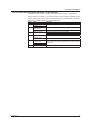
How to Use This Manual DX’s version and functions described in this manual The contents of this manual cover DXs with hardware style number 3 and firmware release number 4. For details on the functions that have been added or changed, see “DX’ s Version and Functions Described in This Manual” in the DX1000/DX1000N or DX2000 User's Manual (IM04L41B01-01E or IM04L42B01-01E). Edition 2 3 4 5 6 7 IM 04L41B01-17E DX Version 1.11 Version 1.21 Release number 2 (Version 2.
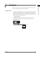
How to Use This Manual Conventions Used in This Manual • Unit • k: Denotes 1000. Example: 5 kg, 100 kHz • K: Denotes 1024. Example: 640 KB • Markings The following markings are used in this manual. Refer to corresponding location on the instrument. This symbol appears on dangerous locations on the instrument which require special instructions for proper handling or use. The same symbol appears in the corresponding place in the manual to identify those instructions.
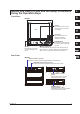
Names and Uses of Parts and the Setup Procedures Using the Operation Keys Front Panel 2 DX1000 LCD Soft keys Press these keys to select the menu displayed on the screen. Rear Panel 1 3 ESC key Press this key to return to the previous screen or cancel the new settings. 4 Arrow keys Press these keys to move between setup items displayed on the screen. 5 DISP/ENTER key Press this key when confirming the setting or when closing the entry box.
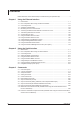
Contents Names and Uses of Parts and the Setup Procedures Using the Operation Keys.............................v Chapter 1 Chapter 2 Chapter 3 vi Using the Ethernet Interface 1.1 1.2 1.3 1.4 1.5 1.6 1.7 1.8 1.9 1.10 1.11 1.12 1.13 1.14 DX Features.......................................................................................................................... 1-1 Flow of Operation When Using the Ethernet Interface........................................................1-11 Connecting the DX..
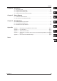
Contents Chapter 4 Chapter 5 Chapter 6 Appendix Responses 4.1 4.2 4.3 4.4 Response Syntax.................................................................................................................. 4-1 Output Format of ASCII Data................................................................................................ 4-6 Output Format of Binary Data............................................................................................. 4-33 Output Format of Instrument Information...
Chapter 1 1.1 Using the Ethernet Interface DX Features 1 Modbus Client • The DX acting as a Modbus client device can connect to a Modbus server device and read or write to the internal register. The read data can be used as communication input data of the computation function* on a computation channel. The data can also be handled on the external input channel**. The data that can be written to the internal register is measured data and computed data.
1.1 DX Features Modbus Server • A Modbus client device can carry out the following operations on the DX that is operating as a Modbus server device.
1.1 DX Features Setting/Measurement Server 2 3 *1 Can be configured on DXs with the /AS1 option. *2 /AS1 option • The following types of data can be output. • Measured, computed*3, and external input*4 data. • Files in the internal memory or files on the external storage medium. • Setup information and status byte. • A log of operation errors and communications. • Alarm summary and message summary. • Relay status information.
1.1 DX Features FTP Server • You can use a PC to access the DX via FTP. You can perform operations such as retrieving directory and file lists from the external storage medium of the DX and transferring and deleting files. In addition, you can also retrieve the directory or file list and transfer files in the internal memory. • On DXs with the /AS1 advanced security option, you cannot create or delete files on the external storage media connected to the DX.
1.1 DX Features FTP Client 1 Using the Ethernet Interface Automatic transferring of files • The display data file, event data file, report data file, snapshot data file, setup file*1, and change settings log file*1 that are created in the internal memory of the DX can be automatically transferred to a remote FTP server. The result of the transfer is recorded in the FTP log. The FTP log can be shown on the DX’s display (see “Log Display” described later) or output to a PC using commands.
1.1 DX Features Login (On DXs without the /AS1 advanced security option) • This function can be used only when using the setting/measurement server, maintenance/test server, and the FTP server functions. • For a description of the settings required to use this function, see the DX1000/ DX1000N or DX2000 User’s Manual (IM04L41B01-01E or IM04L42B01-01E). • For a description of the login process of the setting/measurement server and maintenance/test server, see appendix 2.
1.1 DX Features Login (On DXs with the /AS1 advanced security option) 2 3 Setting/Measurement Server • User Registration You can use the DX login function to register users. There are two user levels: administrator and user. Administrator There are two types of connections that can be made to the DX setting/measurement server: connections to the setting function (setting connection) and connections to the monitoring function (monitoring connections).
1.1 DX Features Web Server Microsoft Internet Explorer can be used to display the DX screen on the PC. • The following two pages are available. • Monitor page: Screen dedicated for monitoring. • Operator page: You can switch the DX screen. You can also modify and write messages. • You can set access control (user name and password specified with the login function) on each page. • The screen can be updated at a constant period (approximately 10 s).
1.1 DX Features 1 E-mail Transmission The available types of e-mails are listed below. E-mail can be automatically transmitted for each item. You can specify two groups of destinations and specify the destination for each item. In addition, you can set a header string for each item. • Alarm mail Reports alarm information when an alarm occurs or clears. Alternatively, reports alarm information only when an alarm occurs.
1.1 DX Features SNTP Server/Client The client function retrieves time information from a specified SNTP server such as at the specified interval. The server function provides time information to DXs connected to the same network. DHCP Client This function can be used to automatically retrieve IP addresses from a DHCP server. You can also manually request or release network information. EtherNet/IP Server (Release number 3 or later) The DX supports the following features.
1.2 Flow of Operation When Using the Ethernet Interface 1 Using the Ethernet Interface Follow the flowchart below to set the Ethernet communications.
1.3 Connecting the DX Connecting to the Port Connector Connect an Ethernet cable to the Ethernet port on the DX rear panel. Ethernet cable CAUTION Do not connect an Ethernet cable whose plug does not comply with FCC specifications. If you do, the DX may malfunction. Connecting to the PC Make the connection via a hub. For a one-to-one connection with a PC, make the connection as shown in the figure below. Multiple DXs can be connected to a single PC in a similar manner.
1.3 Connecting the DX Setting the IP Address and Host Information 1 Using the Ethernet Interface • DX1000 ◊ Press MENU (to switch to setting mode), hold down FUNC for 3 s (to switch to basic setting mode), and select the Menu tab > Communication (Ethernet) > IP address. ◊ Press MENU (to switch to setting mode), hold down FUNC for 3 s (to switch to basic setting mode), and select the Menu tab > Communication (Ethernet) > Host settings.
1.3 Connecting the DX When using a fixed IP address • DHCP Set DHCP to Not. • IP address Set the IP address to assign to the DX. • Subnet mask Set the subnet mask according to the system or network to which the DX belongs. • Default gateway Set the IP address of the gateway. • Host name Set the DX’s host name using up to 64 alphanumeric characters. You do not have to set this parameter. • Domain name Set the network domain name that the DX belongs to using up to 64 characters.
1.3 Connecting the DX Requesting/Releasing Network Information from DHCP Requesting Network Information 1. Display the network information screen. ◊ Press FUNC and select Network info. 1 Using the Ethernet Interface You can manually request or release network information such as the IP address. This operation applies when DHCP is set to Use. Perform the request or release after displaying the network information screen. 2 3 4 5 2. Execute the network information request.
1.3 Connecting the DX Releasing Network Information 1. Display the network information screen. ◊ Press FUNC and select Network info. 2. Execute the network information release. ◊ Press FUNC and select Network info > Release. The network information is released.
1.3 Connecting the DX Setting the Communication Status 1 Using the Ethernet Interface ◊ Press MENU (to switch to setting mode), hold down FUNC for 3 s (to switch to basic setting mode), and select the Menu tab > Communication (Ethernet) > Keep alive, Timeout. 2 3 4 Setting the keepalive 5 Setting the application timeout 6 To disconnect when there is no response to the test packets that are periodically sent, select On. Otherwise, select Off.
1.4 Sending E-mail Messages Settings for Sending E-mail Set the server configuration and the contents of the e-mail transmission. ◊ Press MENU (to switch to setting mode), hold down FUNC for 3 s (to switch to basic setting mode), and select the Menu tab > Communication (Ethernet) > E-Mail.
1.4 Sending E-mail Messages 1 Basic Settings Set the SMTP server and mail address. Enter the host name or IP address of the SMTP server. Using the Ethernet Interface • SMTP server name 2 • Port number Unless specified otherwise, set the number to the default value. The default value is 25. • Security (release number 3 or later) Select PbS if you want to enable POP before SMTP. To enable authenticated e-mail transmission (Authentication SMTP), select Auth (release numbers 4 and later).
1.4 Sending E-mail Messages • Include source URL Select On to attach the source URL. Attach the URL when the Web server is enabled. • Subject Enter the subject of the e-mail using up to 32 alphanumeric characters. The default setting is Alarm_summary. • Header1 and Header2 Enter header 1 and header 2 using up to 64 characters. • Send alarm action (Release number 3 or later) To send e-mail when an alarm occurs and when it is cleared, select On+Off. To only send e-mail when an alarm occurs, select On.
1.4 Sending E-mail Messages Configuring the POP3 Server Connection (Release number 3 or later) 1 Using the Ethernet Interface Specify how the DX operates when it connects to a POP server. ◊ Press MENU (to switch to setting mode), hold down FUNC for 3 s (to switch to basic setting mode) and select the Environment tab > Communication > POP3 Details. 2 3 4 Send delay [seconds] Enter the delay between a POP3 server authentication and the transmission in the range of 0 to 10 seconds.
1.4 Sending E-mail Messages E-mail Format The formats of alarm e-mails, scheduled e-mails, system e-mails, invalid user mails (/AS1 advanced security option), report e-mails, and test e-mails are given below. For details on the common display items, see “Common Display Items for All Formats” in this section.
1.4 Sending E-mail Messages 1 Scheduled E-mail Format • Subject Using the Ethernet Interface Subject:Periodic_Data • Syntax 2 header1CRLF header2CRLF CRLF Periodic_data.CRLF CRLF hostCRLF CRLF
1.4 Sending E-mail Messages System Mail (Power Failure) Format • Subject Subject: System_warning • Syntax header1CRLF header2CRLF CRLF Power_failure.CRLF CRLF hostCRLF CRLF mo/dd_hh:mi:ssCRLF mo/dd_hh:mi:ssCRLF CRLF Access_the_following_URL_in_order_to_look_at_a_screen.CRLF http://host.domain/CRLF CRLF System Mail (Memory Full) Format • Subject Subject:System_warning • Syntax header1CRLF header2CRLF CRLF Memory_full.
1.4 Sending E-mail Messages 1 System Mail (Error) Format • Subject Using the Ethernet Interface Subject:System_warning • Syntax 2 header1CRLF header2CRLF CRLF Error.CRLF CRLF hostCRLF CRLF mo/dd_hh:mi:ssCRLF ERROR:fffCRLF ···························· ”Operation_aborted_because_an_error_was_found_in_media.”CRLF CRLF Access_the_following_URL_in_order_to_look_at_a_screen.CRLF http://host.
1.4 Sending E-mail Messages Report Mail Format • Subject Subject:Report_data • Syntax header1CRLF header2CRLF CRLF ti_report.CRLF CRLF hostCRLF CRLF mo/dd_hh:mi:ssCRLF ccc···cCRLF eee···eCRLF eee···eCRLF eee···eCRLF eee···eCRLF uuu···uCRLF ···························· CRLF Access_the_following_URL_in_order_to_look _at_ a_ screen.CRLF http://host.
1.4 Sending E-mail Messages 1 Test E-mail Format • Subject Using the Ethernet Interface Subject: Test • Syntax 2 Test_mail.CRLF CRLF hostCRLF CRLF
1.5 Monitoring the DX on a PC Browser Setting the Web Server Function From the basic setting mode menu, set the server function and Web page of Communication (Ethernet). Setting the Web server ◊ Press MENU (to switch to setting mode), hold down FUNC for 3 s (to switch to basic setting mode), and select the Menu tab > Communication (Ethernet) > Server > Server modes. • Web For the Web item under Server, select Use or Not (don’t use).
1.5 Monitoring the DX on a PC Browser Page Type Setting the monitor page • Page type Select Monitor. • Setting On/Off To display the monitor page on a browser, select On; otherwise, select Off. • Access control To use access control, select On. On DXs without the /AS1 advanced security option: If you set this to On, you must enter a user name and password to display the monitor page. Set the user name and password through the Login item.
1.5 Monitoring the DX on a PC Browser Monitoring with a Browser Setting the URL Set the URL appropriately according to the network environment that you are using. You can access the DX by setting the URL as follows: http://host name.domain name/file name http Protocol used to access the server. Host name.domain name Host name and domain name of the DX. You can also use the IP address in place of the host name and domain name. File name File name of the monitor page and operator page of the DX.
1.5 Monitoring the DX on a PC Browser 1 Login (On DXs with the /AS1 advanced security option) You need to configure the following settings to use the login function. 2 Setting Communication login (Security > Communication) Login 3 Web page Description and Reference To access the DX through a communication interface, you must log in. See section 1.3 in the Advanced Security Function (/AS1) User’s Manual. Register users whose mode is “Web.” See section 1.
1.5 Monitoring the DX on a PC Browser Contents of the Monitor Page Note If the DX is in setting mode or basic setting mode, you cannot display the monitor page or the operator page. If you try to do so, an error message appears. For details on the different modes, see the Operation Guide (IM04L41B01-02E or IM04L42B01-02E). Refresh the screen Display the alarm summary Displays the alarm summary in a separate window.
1.5 Monitoring the DX on a PC Browser Sounding and Stopping Alarm Sounds The alarm can be sounded on a PC that can produce sound. The popup blocking settings of your browser may prevent the alarm sound window from appearing. 1 Using the Ethernet Interface When an alarm occurs on the DX, the alarm sound popup window appears, and an alarm is sounded. 2 3 4 The alarm sound stops when you click Close.
1.5 Monitoring the DX on a PC Browser Contents of the Operator Page When the multi batch function (/BT2 option) is not in use Message Write a message. Does not appear on DXs with the /AS1 advanced security option. Select the trend screen Directly select the group you want to display. Select the historical screen Directly select the group you want to display. Search by date and time Search data by date and time.
1.5 Monitoring the DX on a PC Browser 1 When the multi batch function (/BT2 option) is in use Batch single mode Using the Ethernet Interface 2 Select the screen mode. List box 3 4 5 6 App Batch overview mode Index Select the screen mode.
1.5 Monitoring the DX on a PC Browser Switching the Screen (Operator page only) • Screen Mode (Only when the multi batch function (/BT2 option) is in use) From the Select Screen Mode list box, select Batch Overview (batch overview mode) or Batch Group# (batch single mode). • Trend and Historical Trend Using the Select Group list box, you can switch to the trend or historical trend display for the group that you specify.
1.5 Monitoring the DX on a PC Browser Alarm Summary Alarm summary example (when the multi batch function (/BT2 option) is not in use) 1 Using the Ethernet Interface Click Alarm Summary to display the alarm summary. Click Refresh to update the data. • You can display information for up to 400 alarms. • Based on the DX settings, the Channel column displays channel numbers, tag comments, or tag numbers and tag comments. • Alarms are displayed using the specified alarm colors.
1.5 Monitoring the DX on a PC Browser Log Displays the message summary*1, error log, FTP log, login log*2, Web operation log, e-mail log, SNTP log, Modbus log, operation log*3, and change settings log*3 in a separate window. From the Log list box, select the log you want to display. Click Refresh to update the data. *1 You can display up to 100 messages and up to 50 added messages. *2 Only on DXs without the /AS1 advanced security option *3 Only on DXs with the /AS1 advanced security option.
1.5 Monitoring the DX on a PC Browser 1 You can display report data in the specified format (layout) and print it. • Procedure • Set the report display layout before you carry out this operation. In the layout, set the report title, the report channels to display, and the item names. • From the operator or monitor page, open the create web report window, and select the report file and the layout to use.
1.
1.5 Monitoring the DX on a PC Browser 1 • Displaying a Report Using the Ethernet Interface 1. Click Report to open the Create Web Report window. 2 3 4 5 6 App 2. Select the layout and report data. Select Layout Index Select the layout title from the list box. Select Report Data Select the report data from the list box. The report data is the data in the DX internal memory. The report data is displayed using the date when the report was created and the report value.
1.5 Monitoring the DX on a PC Browser 3. Click Create. The report data appears in a separate window. • Printing a Report Title You can edit the report title. Click within the report title box, and edit the text using up to 64 characters. The title that you enter here does not affect the DX setting. Comment You can enter two lines of comments in the comment text field. Click within the comment text field, and enter text. Print Print the report from the browser.
1.5 Monitoring the DX on a PC Browser 1 Printing the Screen (Release number 3 or later) You can print a screen capture with an optional title and comment attached. Using the Ethernet Interface Title box The default title is the IP address or host name. You can overwrite the default title with your own title. 2 3 4 5 6 Comment input box Enter comments. You can enter more than five lines of comments, but only the first five lines will be printed. App Print button Opens the print window.
1.5 Monitoring the DX on a PC Browser Writing Messages (Operator page only) You can assign a text string to one of the DX messages 1 through 10 and write the message to a specified group at the same time. The maximum message length is 32 alphanumeric characters. The current message setting is overwritten. This operation is not available on DXs with the /AS1 advanced security option.
1.5 Monitoring the DX on a PC Browser You can search for measured data at the specified date and time and display the results. You can search the display data or event data in the DX internal memory. Note • • • This function uses the DX function that displays the measured data at the specified date and time. You can search the last 10 years of data excluding the data before year 2000. For details on the display conditions, see section 4.
1.6 Accessing the Measurement Data File on the DX from a PC You can access data files stored on the external storage medium. Setting the FTP Server Server Function ◊ Press MENU (to switch to setting mode), hold down FUNC for 3 s (to switch to basic setting mode), and select the Menu tab > Communication (Ethernet) > Server > Server modes. • FTP For the FTP item under Server, select Use or Not (don’t use).
1.6 Accessing the Measurement Data File on the DX from a PC Note • An example of retrieving files using a browser is described below. In the Address box, enter the following: ftp://host name.domain name/file name Drag the data you want to retrieve from the /MEMO/DATA0 folder in the case of internal memory data or the /DRV0 folder in the case of data on the external storage medium to the PC. You can also use the IP address in place of the “host name.domain name.
1.7 Transferring Data Files from the DX The display and event data files, report data files, snapshot data files, setup files, and change settings log files created in the internal memory of the DX can be automatically transferred using FTP at the time the files are created. Files to Be Transferred via FTP The display or event data files are automatically transferred to the FTP destination described in the next section at appropriate times.
1.7 Transferring Data Files from the DX *1 See the Advanced Security Function (/AS1) User’s Manual. Setting the FTP Client ◊ Press MENU (to switch to setting mode), hold down FUNC for 3 s (to switch to basic setting mode), and select the Menu tab > Communication (Ethernet) > FTP client > FTP transfer file. FTP transfer file settings FTP connection destination settings 1 Using the Ethernet Interface • Even if you turn the power off during FTP transfer wait time, the elapsed time is recorded.
1.7 Transferring Data Files from the DX Setting the FTP connection destination Consult your network administrator when setting parameters such as the primary/ secondary FTP servers, port number, login name, password, account, and availability of the PASV mode. • FTP connection You can specify two destination FTP servers, Primary and Secondary. If the primary FTP server is down, the file is transferred to the secondary FTP server.
1.7 Transferring Data Files from the DX 1 Testing the FTP Transfer Using the Ethernet Interface You can test whether a test file can be transferred from the DX to an FTP server. ◊ Press FUNC and select FTPtest. 2 Items to check before performing this test • Connect the Ethernet cable correctly. For the connection procedure, see section 1.3. • Check that the Ethernet interface settings are correct. For the procedure, see section 1.3.
1.8 Synchronizing the Time The DX time can be synchronized to the time on an SNTP server. The DX can also function as an SNTP server. Setting the SNTP Client Synchronize the DX time to the time on an SNTP server. ◊ Press MENU (to switch to setting mode), hold down FUNC for 3 s (to switch to basic setting mode), and select the Menu tab > Communication (Ethernet) > SNTP client. • Use/Not Select Use to use the SNTP client function; Otherwise, select Not.
1.8 Synchronizing the Time Setting the SNTP Server 1 Using the Ethernet Interface Carry out the steps below to run the DX as an SNTP server. ◊ Press MENU (to switch to setting mode), hold down FUNC for 3 s (to switch to basic setting mode), and select the Menu tab > Communication (Ethernet) > Server > Server modes 2 3 4 5 • SNTP For the SNTP item under Server, select Use or Not (don’t use).
1.9 Using the Modbus Server Function The DX is used as a Modbus server. For the Modbus specifications, see section 6.3. Setting the Modbus Server Carry out the steps below to enable another device to read the DX data or write data to the DX using Modbus. ◊ Press MENU (to switch to setting mode), hold down FUNC for 3 s (to switch to basic setting mode), and select the Menu tab > Communication (Ethernet) > Server > Server modes.
1.9 Using the Modbus Server Function Port Number Reading/Writing the DX Data on Another Device Another device (client device) sends commands to the DX to read the DX data or write data to the DX. You can perform some operations, such as memory start, by writing in the registers. For the function codes that the DX supports and the DX registers that the client device can access, see “Modbus Server Function” in section 6.3.
1.10 Using the Modbus Client Function The DX is used as a Modbus client. For the Modbus specifications, see section 6.3. Setting the Modbus Client Carry out the steps below to enable the DX to read the data of another device or write data to another device using Modbus. ◊ Press MENU (to switch to setting mode), hold down FUNC for 3 s (to switch to basic setting mode), and select the Menu tab > Communication (Ethernet) > Modbus client.
1.10 Using the Modbus Client Function • Unit • No. 1 Using the Ethernet Interface Select Auto if the unit number of the destination server is not required; Otherwise, select Fixed. If you select Fixed, the unit number item is displayed. 2 Enter a fixed unit number in the range of 0 to 255. Setting the transmitted commands • Client command number 3 Select 1 to 16 for the transmitted command numbers to be configured. • Command type Set the command type to Off, R, R-M, W, W-M, or E-M.
1.10 Using the Modbus Client Function • Type Data type. Select INT16, UINT16, INT32_B, INT32_L, UINT32_B, UINT32_L, FLOAT_B, or FLOAT_L. The data type you can specify vary depending on the command type. See section 6.3.
1.10 Using the Modbus Client Function Examples of Setting Commands Connection DXAdvanced (Modbus client) example Instrument A (Modbus server 1) Instrument B (Modbus server 2) Instrument C (Modbus server 3) Ethernet 1 Using the Ethernet Interface The following are examples of setting commands for the Modbus Client function. For the Modbus Master function, substitute “master” for “client,” and “slave” for “server.
1.10 Using the Modbus Client Function Loading to External Input Channels (DX2000 Only) The DX inputs the data loaded from the server to the external input channel as a 16-bit signed integer type. • Example 1 Load the values of the 16-bit unsigned integers assigned to register 30001 of instrument C to external input channel 201.
1.10 Using the Modbus Client Function Load the value of the signed 16-bit integer assigned to the hold register (400001) of instrument A to C05. The value of C05 is only written to the hold register (400001) of instrument A when a value write operation is performed from the custom display.
1.10 Using the Modbus Client Function Checking the Modbus Operating Status Displaying the Modbus Operating Status ◊ Press DISP/ENTER and select INFORMATION > MODBUS CLIENT. Note To display MODBUS CLIENT on the screen selection menu, you need to change the setting using the menu customize function. The operation is as follows: ◊ Press MENU (to switch to setting mode), and select the Menu tab > Menu customize > Display menu 1. 2. Select INFORMATION > MODBUS CLIENT Press the View soft key.
1.10 Using the Modbus Client Function Resuming Command Transmission Data When Communication Is Stopped and during Connection Retrials If the command transmission stops such as due to a connection drop, the status turns orange or red, and the communication input data and external input channel data are error data. On communication channels, “+OVER” or –OVER is displayed according to the DX settings. “*****” is displayed on external input channels.
1.10 Using the Modbus Client Function Function for Automatically Assigning MW100s to the Modbus Client (DX2000 Only) The following setup is carried out from the DX using YOKOGAWA’s MW100 Data Acquisition Unit as a Modbus server. If the DX2000 is a Modbus client, MW100s, Modbus servers on the network, can be automatically assigned to the DX2000. This function can be used only on DX2000s with the external input channel function (/MC1 option).
1.10 Using the Modbus Client Function Setup Items DX external input channels DX MW100 meas. channels CH201 CH001 CH220 CH020 CH221 CH001 CH240 CH014 CH241 CH001 CH270 CH030 Order of automatic assignment MW100 MW100 MW100 MW100 Meas. channels CH001 to CH020 1 Meas. channels CH001 to CH004, CH011 to CH014 2 Meas. channels CH001 to CH030 3 2 3 4 5 • Range Settings The range settings of the MW100 (including the span and unit) are set automatically to the external input channels.
1.10 Using the Modbus Client Function Note About the MW100 • MW100s that support auto setting are those with firmware version R2.22 or later. • MW100 modules that can be automatically set are the following input modules. The installable input modules vary depending on the MW100 firmware version.
1.11 Usage Example of the Modbus Function 1 System Configuration and Actions Uses the measurement channel, computation channel, and communication input data as described in the figure below. Assumes other conditions are set properly. Ethernet Command Using the Ethernet Interface Explains the setting example for both Modbus client and server on DX1000s connected via the Ethernet.
1.11 Usage Example of the Modbus Function Settings on the DX1000 Server (Modbus Server) Setting the Modbus Server Function ◊ Press MENU (to switch to setting mode), hold down FUNC for 3 s (to switch to basic setting mode), and select the Menu tab > Communication (Ethernet) > Server > Server modes. Item Modbus Settings Use About the Port Number The port number is 502 by default.
1.11 Usage Example of the Modbus Function Setting the DX1000 Client (Modbus Client) Registering the Destination Server Register the DX1000 server to number 1. The IP address of the DX1000 server is “190.168.1.101” as an example. ◊ Press MENU (to switch to setting mode), hold down FUNC for 3 s (to switch to basic setting mode), and select the Menu tab > Communication (Ethernet) > Modbus client > Modbus server settings.
1.11 Usage Example of the Modbus Function Setting the Computation Channel ◊ Press MENU (to switch to setting mode), and select the Menu tab > Math channel > Expression, Alarm. Item First-CH, Last-CH Math Calculation expression Span_L Span_U Unit Settings 101 On C01*K01 –2.0000 2.0000 V ◊ Press MENU (to switch to setting mode), and select the Menu tab > Math channel > Constant. Item Number of constant Value Settings K01 0.
1.11 Usage Example of the Modbus Function Starting the Computation (DX1000 Client) 1 Using the Ethernet Interface ◊ Press FUNC and select Math start. The computation starts. A computation icon is displayed on the status display section. The value of the computation channel 101 in the GROUP 1 of the DX1000 client varies in conjunction with the measured value of the measurement channel 1 on the DX1000 server.
1.12 Using the Setting/Measurement Server This section explains how to use the setting/measurement server. You can use this function to send commands to retrieve data from the DX and to control it. For information about the maximum number of simultaneous connections, see section 6.1. When Not Using the Login Function Access the server using the user name “admin” or “user.
1.12 Using the Setting/Measurement Server Logging In 1 Note Using the Ethernet Interface Perform the operations that are appropriate for your PC, software, and network environment. This section explains the operations that a user performs on the PC before he or she logs in and how the DX responds to those operations. For information about the flow of login processing, see appendix 2.
1.12 Using the Setting/Measurement Server The DX returns the following message: E1 408 “Enter password again for confirmation.” 7. Enter the password that you entered in step 6. The DX returns the following message: E0 You are now logged in. Logging In after the Password Has Been Set 1. Specify the host name or IP address of the DX that you want to connect to. Or, specify the port number (34260) of the setting/measurement server.
1.12 Using the Setting/Measurement Server Sending Commands Connected Function Setting function Administrator User All the commands are available. Monitoring function All the output commands except for ME and MO and some of the control commands are available (operations that are forbidden by the user privilege settings are not available). All the output commands except for ME and MO and control commands CM and CE.
1.12 Using the Setting/Measurement Server Disconnection The connection is closed when: • A command is sent that closes the connection. The CC0 command is sent. • A command that results in the exiting of basic setting mode has been executed. If you log in to the setting function and initialize the setup data (EC command), load settings (YO command), or close system mode (YE command), the communication connection is closed, along with other connections.
1.13 Using the Maintenance/Test Server 1 Access the server using the user name “admin” or “user.” You can use either the administrator (admin) or user commands, depending on which name you used to log in. When Using the Login Function (Standard) Log in as an administrator or user who has been registered on the DX. Of the commands in chapter 3, you can use either the administrator or user commands, depending on which name you used to log in.
1.14 Using the Password Management Function (/AS1 option) Overview System Configuration The following figure shows the configuration of the authentication system.
1.14 Using the Password Management Function (/AS1 option) Flow of Operation KDC server configuration Time synchronization Configure the KDC server. DX configuration Management initiation Configure the DX password management function. 2 3 Synchronize the time on the DX with that on the KDC server. 1 Using the Ethernet Interface To use the password management function, you must configure a KDC server and the DX. First configure the KDC server, and then configure the DX.
1.14 Using the Password Management Function (/AS1 option) DX Settings (KDC server to connect to and authentication key) ◊ Press MENU (to switch to setting mode), hold down FUNC for 3 s (to switch to basic setting mode), and select the Menu tab > Communication(Ethernet) > Password management > KDC connection, Certification key. KDC connection Certification key KDC Connection You can specify a primary and a secondary KDC server.
1.14 Using the Password Management Function (/AS1 option) KDC Server Configuration Example Overview The necessary Active Directory management steps on Windows Server 2008 are the creation of a host account, property changes, mapping of the host principal to the host account*1, and the creation of a key tab file (this step can be omitted).
1.14 Using the Password Management Function (/AS1 option) 2. Enter dxadv into the First name, Full name, and User logon name boxes. 3. Enter record-1 in the Password box. Select the Password never expires check box. 4. Click Finish to complete the creation of the new account.
1.14 Using the Password Management Function (/AS1 option) Changing the Properties of the New Account 1 Using the Ethernet Interface Select the check boxes listed below. Clear all other check boxes. This account supports Kerberos AES 256 bit encryption Password never expires • The “Password never expires” check box was selected previously in step 3, so it will also be selected in this window. • If you clear all the encryption method check boxes, RC4 will be used.
1.14 Using the Password Management Function (/AS1 option) Mapping the host principal to the host account Open the command prompt, and execute the following command. ktpass –princ host/dxadv@(the name of the realm you are using) -pass record-1 – mapuser dxadv –ptype KRB5_NT_PRINCIPAL –crypto All –out C:\yokogawa\dxadv. keytab The file dxadv.keytab is created in the C:\yokogawa folder. Create an Active Directory User Account and Change Its Properties Create an Active Directory DX user account.
1.14 Using the Password Management Function (/AS1 option) About Mapping ktpass Settings Setup Item princ pass crypto mapuser ptype out ARC4 AES128 AES256 Windows Server Windows Server 2003 2008 host/(host principal)@(realm name) Password RC4-HMAC-NT RC4-HMAC-NT AES128-SHA1 AES256-SHA1 Host account KRB5_NT_PRINCIPAL (Destination folder name)\(file name).keytab Example host/dxadv@EXAMPLE. COM record-1 RC4-HMAC-NT dxadv KRB5_NT_PRINCIPAL c:\temp\dxadv.
1.14 Using the Password Management Function (/AS1 option) ktpass Execution Example (Windows Server 2008) This execution example is different from the configuration example on the previous page. Settings on the DX Configure the following settings on the DX. For the setup procedure, see page 1-80. Item Host principal Realm name Password Encryption method KDC server name Port number Setup Items dxadv Specify the realm name. record-1 AES256 Specify the KDC server name.
Chapter 2 2.1 Using the Serial Interface DX Features 1 Serial communication can be performed using RS-232 or RS-422/485. Explains the serial communication functions. • The DX can connect to a Modbus slave device and read or write to the internal register. The read data can be used as communication input data of the computation function* on a computation channel. The data can also be handled on the external input channel.
2.1 DX Features Modbus Slave • A Modbus master device can carry out the following operations on the DX that is operating as a Modbus slave device.
2.2 Flow of Operation When Using the Serial Interface 1 The flow chart below shows the procedure to set the communication using RS-232 or RS-422/RS-485. The procedure varies for RS-232 and RS-422/RS-485.
2.3 Connecting the DX Connecting the cable Connect a cable to the serial port on the DX rear panel. RS-232 Connection Procedure Connect a cable to the 9-pin D-sub RS-232 connector. Connector pin arrangement and signal names 2 1 3 4 5 (Rear panel) 6 7 8 9 Each pin corresponds to the signal indicated below. The following table shows the signal name, RS-232 standard, JIS, and ITU-T standard signals.
2.3 Connecting the DX 1 • Connection example • OFF-OFF/XON-XON PC PC SD RD RS CS SG SD RD RS CS SG 3 2 7 8 5 DX SD RD RS CS SG 2 • XON-RS(XON-RTS) PC SD RD RS CS SG 3 2 7 8 5 DX SD RD RS CS SG Using the Serial Interface 3 2 7 8 5 SD RD RS CS SG • CS-RS(CTS-RTS) DX 3 The connection of RS on the PC and CS on the DX is not necessary. However, we recommend that you wire them so that the cable can be used in either direction.
2.3 Connecting the DX • XON-XON • Data transmission control Software handshaking is performed between the DX and the PC. When an “X-OFF” code is received while sending data to the PC, the DX stops the data transmission. When the DX receives the next “X-ON” code, the DX resumes the data transmission. The CS signal received from the PC is ignored. • Data reception control Software handshaking is performed between the DX and the PC.
2.3 Connecting the DX 1 RS-422/485 Connection Procedure Terminal arrangement and signal names Connect a cable to the clamp terminal. 2 Using the Serial Interface (rear panel) FG SG SDB RDB SDA RDA 3 Each terminal corresponds to the signal indicated below. Signal Name FG SG SDB SDA RDB RDA Meaning Frame ground of the DX. Signal ground. Send data B (+). Send data A (–). Receive data B (+). Receive data A (–).
2.3 Connecting the DX Connection example to the host device A connection can be made with a host device having a RS-232, RS422, or RS-485 port. In the case of RS-232, a converter is used. See the connection examples below for a typical converter terminal. For details, see the manual that comes with the converter.
2.3 Connecting the DX Note • 1 2 Using the Serial Interface • The method used to eliminate noise varies depending on the situation. In the connection example, the shield of the cable is connected only to the DX’s ground (one-sided grounding). This is effective when there is a difference in the electric potential between the computer’s ground and the DX’s ground. This may be the case for long distance communications.
2.4 Setting the Serial Communication ◊ Press MENU (to switch to setting mode), hold down FUNC for 3 s (to switch to basic setting mode), and select the Menu tab > Communication (Serial) > Basic settings. For RS-232 • Baud rate Select 1200, 2400, 4800, 9600, 19200, or 38400 (bps). • Data length Select 7 or 8 (bits). To output the data in binary format, select 8. • Parity Set the parity check method to Odd, Even, or None. • Handshaking Select Off:Off, XON:XON, XON:RS, or CS:RS.
2.5 Using the Modbus Slave Function 1 The DX is used as a Modbus slave. For the Modbus specifications, see section 6.3. 2 Select Modbus as a protocol on the Basic settings. For detail, see section 2.4, “Setting the Serial Communication.” Reading/Writing the DX Data on Another Device Another device (master device) sends commands to the DX to read the DX data or write data to the DX. You can perform some operations, such as memory start, by writing in the registers.
2.6 Using the Modbus Master Function The DX is used as a Modbus master. For the Modbus specifications, see section 6.3. Setting the Serial Communication Select Modbus-M as a protocol on the Basic settings. For detail, see section 2.4, “Setting the Serial Communication.” Setting the Modbus Master ◊ Press MENU (to switch to setting mode), hold down FUNC for 3 s (to switch to basic setting mode), and select the Menu tab > Communication (Serial) > Modbus master > Basic settings or Command settings.
2.6 Using the Modbus Master Function E-M: Read to the communication input data (32-bit floating point type) from the server/write the custom display value to the server (release numbers 4 and later). R can be selected on DX2000s with the external input channel (/MC1) installed. R-M, W-M, and E-M can be selected on models with the computation function (/M1 or /PM1) option installed. Enter the first and last channel numbers of input/output.
2.6 Using the Modbus Master Function • Communication conditions The read cycle, Inter-block delay, Time out, Auto recovery, and Retrials settings are displayed. • Communication Status The communication status is displayed using the status lamp and the detail code. Status Lamp Detail Code Meaning Green Good Communication is operating normally. Yellow Command is readying. Red Communication is stopped. Common to yellow None No response from the slave device.
2.7 Usage Example of the Modbus Function 1 System Configuration and Actions Uses the measurement channel, computation channel, and communication input data as described in the figure below. Assumes other conditions are set properly. Serial communication Measured data DX1000 slave (Modbus slave) Measurement channel 1 Input range: -2.0000 to 2.
2.7 Usage Example of the Modbus Function Settings on the DX1000 Slave (Modbus Slave) Setting the Modbus Slave Function ◊ Press MENU (to switch to setting mode), hold down FUNC for 3 s (to switch to basic setting mode), and select the Menu tab > Communication (Serial) > Basic settings. Item Address Protocol Settings 1 Modbus Setting the Measurement Channel ◊ Press MENU (to switch to setting mode), and select the Menu tab > Meas channel > Range, Alarm.
2.7 Usage Example of the Modbus Function 1 Setting the DX1000 Master (Modbus Master) Assumes the settings other than those below are left to default values. Setting the Modbus Master Function ◊ Press MENU (to switch to setting mode), hold down FUNC for 3 s (to switch to basic setting mode), and select the Menu tab > Communication (Serial) > Basic settings.
2.8 Using the Setting and Measurement Function This section explains the setting and measurement function. You can use this function to send commands to retrieve data from the DX and to control it. Connecting to the DX Perform the operations that are appropriate for your PC, software, and network environment. RS-232 The DX is ready to receive commands as soon as you connect it to the PC.
2.8 Using the Setting and Measurement Function Commands That You Can Perform after Logging In To log in, a user must be registered on the DX and have permission to log in through communication commands. The commands that administrators and users can execute are listed in the table below. For details about the commands, see chapter 3. For information about the responses to the commands, see chapter 4.
2.8 Using the Setting and Measurement Function Users cannot execute operations (commands) that are not allowed under their user privileges. The correspondence between the commands that can be used and the user privilege settings are indicated in the table below. For information about how to configure the settings using key operations, see section 2.1 in the Advanced Security Function (/AS1) User’s Manual (IM 04L41B01-05EN).
2.9 Using Barcode Input (/AS1 option) 1 You can use barcode input to supplement the key input. You can only use barcode input on models with the /AS1 advanced security option. ◊ Press MENU (to switch to setting mode), hold down FUNC for 3 s (to switch to basic setting mode), and select the Menu tab > Communication (Serial) > Basic settings. See section 2.4. Protocol Using the Serial Interface Settings on the DX 2 3 4 Select [Barcode] to use the barcode protocol.
2.
2.9 Using Barcode Input (/AS1 option) Operation Log 1 Barcode Readers 2 Operations are recorded in the DX operation log. The operator is the user who was logged in using the DX keys. Operation Examples This section contains operation examples. In this section, “CRLF” is used to indicate a terminator. For information about terminators, see page 3-2.
Chapter 3 Commands 3.1 Command Syntax 1 Command Syntax The syntax of the setting/basic setting/output commands (see sections 3.4 to 3.9) of the DX is given below. ASCII codes (see appendix 1) are used for the character codes. For the syntax of the maintenance/test commands (see section 3.10) and instrument information output commands (see section 3.11), see the corresponding sections or the examples for each command.
3.1 Command Syntax Query • A question mark is used to specify a query. • By placing a query after a command or parameter, the setting information of the corresponding command can be queried. Some commands cannot execute queries. For the query syntax of each command, see sections 3.4 to 3.7. SR[ p1]? SR? or SRp1? can be executed. Example 1 SA[ p1[,p2]]? SA?, SAp1?, and SAp1,p2? can be executed. Example 2 Delimiter • A comma is used as a delimiter. • Parameters are separated by delimiters.
3.1 Command Syntax Response The DX returns a response (affirmative/negative response) to a command that is delimited by a single terminator.* The controller should follow the one command to one response format. When the command-response rule is not followed, the operation is not guaranteed. For the response syntax, see section 4.1. 1 2 * Commands dedicated to RS-422/485 (see section 3.9) and instrument information output commands (section 3.11) are exceptions.
3.2 A List of Commands When the /AS1 Advanced Security Option Is Not in Use DX Execution Modes here are two execution modes on the DX. If you attempt to execute a command in a T mode that is different from the specification, a syntax error occurs. Use the DS command to switch to the appropriate execution mode, and then execute the command. Query commands can be executed in either mode. • Basic setting mode Measurement and computation are stopped, and settings are changed in this mode.
3.
3.
3.2 A List of Commands Basic Setting Commands Note • The settings that are changed using the YA, YK, RU, YQ, YS, YB, YD, WS, WW, and WQ commands are activated after saving the new settings using the XE command and restarting the DX. • When you execute the YE or YO command, communication is disconnected. Commands listed after the YO or YE command are ignored.
3.
3.2 A List of Commands 1 When the /AS1 Advanced Security Option Is in Use DX Execution Modes The DX has five execution modes. The modes that each command can be executed in are predetermined. Trying to execute a command in the wrong mode results in a syntax error. Before executing a command, use a mode switching command to switch to the appropriate mode. Queries can be executed in any mode. The letters in parentheses in the titles below are the used to represent the different modes in explanations.
3.2 A List of Commands Administrators and Users The distinction between administrators and users indicates the user levels set through the DX Ethernet login function. For details, see section 1.2. “Yes” and “No” in the table indicate the following: Yes: The command can be used. No: The command cannot be used.
3.2 A List of Commands Setting Commands (/AS1) To apply settings that you have changed using the setting commands, you need to save the settings using the BE command.
3.2 A List of Commands Command Name NW NG NH FR SY SM Function Sets an annunciator display Sets a Web report layout Sets Web report layout details Sets the interval for acquiring data to the FIFO buffer Sets a four panel display Sets the custom menu Execution Mode S S S OSsb Setting Connection Administrator User Yes No Yes No Yes No Yes No OS S Yes Yes Yes No * Monitor Connection No No No No Page No No 3-34 3-34 3-33 3-33 3-33 3-33 * Operations are limited by the user privilege settings.
3.2 A List of Commands Control Commands (/AS1) To apply settings that you have changed using the basic setting commands, you need to save the settings using the YE command.
3.2 A List of Commands Basic Setting Commands (/AS1) • To apply settings that you have changed using the basic setting commands, you need to save the settings using the YE command. • The settings that are returned in response to a query in basic setting mode contain the new settings even if they are not saved. However, the new settings are not activated unless you save them.
3.
3.3 Setup Parameters The measurement range and setup range of parameters used in a command vary depending on the combination of the command, range, and options. Parameter Input Example of Measurement Range The span upper and lower limit parameters of the SR command (input range setting command) requires all digits including those to the right of the decimal to be entered. For example, if you want to set the upper limit to 1.0000 V when the measurement range is -2.0000 V to 2.0000 V, the value is 10000.
3.3 Setup Parameters Measurement Range Parameters The table below shows the relationship between the input types and range parameters. For a description of the selectable range, see the DX1000 or DX2000 User’s Manual.
3.
3.4 Setting Commands 3.
3.4 Setting Commands • For parameters p7, p8, and p9, either set all three parameters or omit all three parameters.
3.4 Setting Commands Example R r T t Set the external input channel 201 span to -150.00 to 150.00. 201,ON,-15000,15000,2 Description • You can use this command on models with the /MC1 external input channel option. • You cannot use this command while recording (memory sampling) in progress. When using the /BT2 multi batch option, you cannot use this command if any of the batch groups is recording (memory sampling).
3.4 Setting Commands • • • • SW Syntax • Scaling input (1-5V, scaling, and square root) –5 to 105% of span (except, within – 30000 to 30000) • Difference high limit and difference low limit alarms Within the measurable range • High limit on rate-of-change and low limit on rate-of-change alarms A value that consists of at least one nonzero digit. For example, 0.0001 for the 2 V range. The maximum value is within the measurable range (except within –30000 to 30000). For example, 3.
3.4 Setting Commands TO Syntax TW Syntax Query Example TO p1 p1 Operation after one cycle ALLCLEAR Clears the entire waveform display and starts drawing a new waveform. DIVCLEAR Clears a section of the waveform display and starts drawing a new waveform. TO? Set the operation after one cycle to all clear.
3.4 Setting Commands display area. • The zone size must be at least 5%. • Set the upper zone boundary position greater than the lower zone boundary position. SP Syntax Query Example Sets a partial expanded display SP p1,p2,p3,p4 p1 Measurement, computation, or external input channel number p2 Partial expanded display (ON, OFF) p3 Boundary position (1 to 99) [%] p4 Boundary value SP[p1]? Partially expand the display of channel 001. Set the boundary position to 25% and the boundary value to 1.
3.4 Setting Commands Query Example p2 p3 p4 p5 p6 SL[p1[,p2]]? Display trip line 1 in red at the 10% position of group 1. Set the line width to 1. SL1,1,ON,10,RED,1 NX Syntax Query Example Sets a display group (release number 3 or later) NX p1,p2,p3,p4,p5 p1 Batch group number Set the number to 1 if multi batch /BT2 is not in use.
3.4 Setting Commands TZ Syntax Query Example Sets a file header • On a DX whose release number is 3 or earlier When you send an SD command, the DX switches to setting mode and sets the date and time. • On a DX whose release number is 4 or later When you send an SD command, the DX sets the date and time without switching to setting mode. TZ p1,p2 p1 Batch group number Set the number to 1 if multi batch /BT2 is not in use.
3.4 Setting Commands Query Example TT? Display waveform horizontally, set the message Query Example direction to vertical, and display waveforms by clearing the current waveforms at memory start. TTHORIZONTAL,ON,VERTICAL Description When using the /BT2 multi batch option, p2 is fixed at ON.
3.4 Setting Commands TG Syntax Query Example Sets a color scale band TG p1,p2,p3,p4,p5 p1 Measurement, computation, or external input channel number p2 Area (OFF, IN, OUT) p3 Color (AUTO or 24 colors (see NL; sets a trip line)) p4 Lower display position limit p5 Upper display position limit TG[p1]? Set the channel 005 color scale band to the range from -1.0000 to 0.5000 V (2-V range), and TP Syntax Query Example NF Syntax set the color to green.
3.
3.
3.4 Setting Commands Description • Set various numbers (relay number, internal switch number, etc.) by referring to the table in section 3.3. • You cannot select some of the p4 (action type) settings depending on the p2 (event type) setting. • You cannot select some of the p4 (action type) • • • • • SK Syntax Query Example settings depending on other DX settings or depending on the installed options.
3.4 Setting Commands Description • You can use this command on models with the /M1 or /PM1 math option. • Set parameters p1 and p2 by referring to the table in section 3.3. • You cannot use this command while computation in progress. • When using the /BT2 multi batch option, you cannot use this command if any of the batch groups is recording (memory sampling).
3.4 Setting Commands Query Example BD[p1]? Set the channel 001 alarm delay to 120 s. BD001,120 Description • Set p1 by referring to the table in section 3.3. • The p2 unit is seconds.
3.4 Setting Commands Query Example FR? Set the FIFO acquisition interval to 1 s. FR1,1S Description • Set the acquisition interval to a value greater than the scan interval. • If you set the scan interval to a value greater than the acquisition interval using the XV command or from the screen, the acquisition interval is automatically set equal to the scan interval. • The DX has a circular FIFO (First In First Out) buffer.
3.4 Setting Commands Example Set the first menu item to TREND and the second menu item to TRENDHISTORY. SMDISP_MAIN,TREND,TRENDHISTORY, Description • If parameter p2 and subsequent parameters are omitted, all menus are hidden. • A command error occurs if you specify the same menu item multiple times. • You can specify up to three separators. If you SM p1,p2,p3,....
3.
3.4 Setting Commands / 3.5 Control Commands SYSTEM_INFO 3.5 NETWORK_INFO SNTP EMAIL_START/STOP BT EMAIL_TEST Syntax FTP_TEST Example BUILDER Custom display builder USRLOCKACK User locked ACK Description • A command error occurs if you specify the same menu item multiple times. • You cannot specify “SEPARATOR.” • You cannot omit parameters using delimiters (, ,). • You cannot hide “LOGOUT.” If you do not include it in the parameters, it is displayed as the last item.
3.5 Control Commands to the currently displayed batch group. • Set parameter p3 by referring to the table in section 3.3. • The setting p2=ANNUNCIATOR is only valid Description On models with the /AS1 advanced security option, use the BE command to return to operation mode.
3.5 Control Commands Example p10 Tag prioritized display (ON, OFF) Enable automatic display switching, switch to the group display, turn on the scale display, and turn off the digital display. UD4,ON,GROUP,ON,OFF Description • Parameter p2 is valid for the trend, digital, and bar graph displays. Use the SE command to set the switching interval. • Parameters p3 to p7 are valid for the trend 2 Example Syntax EV Syntax section 3.3.
3.5 Control Commands Example MS Syntax Set the trend interval to the secondary trend interval.
3.5 Control Commands Example p1 Mode 0 1 Operation mode Basic setting mode Set the mode to basic setting. DS1 using basic setting commands, you must use the XE command to save the settings. Be sure to use the XE command to save the settings before switching the execution mode back to operation. If you do not save the settings and change the execution mode back to operation, the DX returns to the previous settings. • This command is invalid on models with the /AS1 advanced security option.
3.5 Control Commands Example Description To use the e-mail transmission function, you must configure the Ethernet interface, set e-mail addresses, and enter the contents you want to transmit.
3.5 Control Commands When p2 is set to SELECT p3 Custom display screen to load into (INTERNAL1 to INTERNAL3 or EXTERNAL 1 to EXTERNAL 25) p4 Name of the file to load from (up to 32 characters) • Do not specify the extension. Example Description • An error occurs when there is no external storage medium (CF) inserted in the DX or when there is an error in the external storage medium. • An error occurs if the external storage medium (CF) does not contain the directory or file name that you specify.
3.5 Control Commands EE Syntax Switches out of operation mode (/AS1 advanced security option) EE p1 p1 Mode switch destination (ENG, SYS) Memory sampling ENG In progress Setting mode during Basic setting mode memory sampling during memory sampling Setting mode Basic setting mode Stopped Example BE Syntax Switch to setting mode. EEENG Syntax Example END Returns to operation mode. Creates a setup file. Returns to operation mode.
3.5 Control Commands / 3.6 Basic Setting Commands p5 Reconfirmation of the new password to use if the current one has expired (up to 20 characters) This parameter is meaningless if the current password has not yet expired. This parameter can be omitted. Example 3.6 WU Settings Log in as user a (whose user ID is “aaaa” and whose password is “aaaaaa”), start computation, and execute memory start.
3.
3.6 Basic Setting Commands • When p6 is set to SEPARATE2, p7 can only be set to OFF. Service ports Syntax WU p1 p2 p3 p4 p5 p1,p2,p3,p4,p5 Setting type (SERVICEPORT) FTP service port (1 to 65535) Web service port (1 to 65535) SNTP service port (1 to 65535) Modbus service port (1 to 65535) p4 p5 p6 p7 p8 p9 Remote contact 3 input (N.O, N.C) Remote contact 4 input (N.O, N.C) Remote contact 5 input (N.O, N.C) Remote contact 6 input (N.O, N.C) Remote contact 7 input (N.O, N.
3.6 Basic Setting Commands DX, the DX switches to the signature window at memory stop, and there is no FTP transfer at signing. BIBATCH,SIGNIN1+2,ON,OFF Description p3 and p4 are valid when p2 is set to SIGNIN1, SIGNIN1+2, or SIGNIN1+2+3.
3.6 Basic Setting Commands Query Example p3 Scan interval (25MS, 125MS, 250MS, 1S, 2S, 5S) p4 A/D integration time (AUTO, 600Hz, 50Hz, 60Hz, 100ms) XV? Set the scan interval to 1 second in normal mode. XV1,NORMAL,1S interval is set to 2 s or 5 s. • On models with multi batch /BT2, you can only set p2 to NORMAL and p3 to 1S, 2S, or 5S.
3.6 Basic Setting Commands Description This command is invalid on models with the /AS1 advanced security option. RN Syntax Query Example Sets basic key login RN p1,p2,p3,p4 p1 Auto logout (OFF, 1MIN, 2MIN, 5MIN, 10MIN) p2 Operation when logged out OFF Disables DX operation DISPLAY Only enables screen operations p3 Whether or not to use a user ID (USE, NOT) p4 Number of password retries (OFF, 3, 5) RN? The parameters after p3 vary depending on how p2 is set as indicated below.
3.
3.6 Basic Setting Commands For creating daily + weekly reports Syntax Query Example • About p4 Because the DX integrates sampled data over each scan interval, the physical value integrated over a given unit of time may be different from the actual integrated value. This occurs if the unit of time is different from the scan interval. If this occurs, set p4 to the same unit of time as that for the physical value that you are measuring.
3.
3.6 Basic Setting Commands YT Syntax Sets FTP transfer timing YT p1,p2,p3,p4 p1 Automatically transfer data when display and event data files are created (ON, OFF) p2 Automatically transfer data when report data files are created (ON, OFF) p3 Automatically transfer data when snapshot data files are created (when snapshot is executed) (ON, OFF) p4 Transfer data when the DX creates a setup Query Example Query YT? Automatically transfer display and event data files.
3.6 Basic Setting Commands Query Example p3 Recipient 2 (ON, OFF) p4 Whether to include source URL (ON, OFF) p5 Subject (up to 32 characters) p6 Header 1 (up to 64 characters) p7 Header 2 (up to 64 characters) YU[p1]? Send report generation notification e-mail that includes the source URL to recipient 1. Set the subject to “Report” and header 1 to “LP2.
3.
3.6 Basic Setting Commands Query Example p6 First register number (30001 to 39999, 40001 to 49999, 300001 to 365535, 400001 to 465535) p7 Type of data assigned to the registers YS? Set the baud rate to 9600, the data length to 8, the parity check to ODD, handshaking to OFF: OFF, the RS-422/485 address to 02, and the protocol to NORMAL. YS9600,8,ODD,OFF:OFF,02,NORMAL Description • You can use this command on models with the /C2 or /C3 serial interface option.
3.6 Basic Setting Commands of channels 003 to 006 in registers 40003 to 40006 in the slave device at address 7.
3.6 Basic Setting Commands WG Syntax Query Example Sets an IP address that is allowed to connect via Modbus WG p1,p2 p1 Registration number (1 to 10) p2 Whether or not to register (ON, OFF) p3 IP address (0.0.0.0 to 255.255.255.255) WG[p1]? Allow connection from 192.168.111.24. Use registration number 1. WG1,ON,192.168.111.
3.7 Output Commands (Control) 3.7 BO Syntax Query Example Syntax Query Example BO p1 p1 Byte order 0 Outputs data MSB first. 1 Outputs data LSB first. BO? Output data MSB first. BO0 Sets the check sum (can only be used during serial communications) CS p1 p1 Checksum usage 0 Do not calculate (value fixed at CS? 1 zero) Calculate Enable (Calculate) the checksum. CS1 Description You can use this command only for serial communications.
3.8 Output Commands (Setting, Measured, and Computed Data Output) 3.8 FC Syntax Most recent measured, computed, and external input data in binary format 6 Relay status and internal switch status 7 Event level switch status p2 First channel number (measurement, computation, or external input channel) p3 Last channel number (measurement, computation, or external input channel) Outputs screen image data FC p1 p1 GET (Output screen image data) Output screen image data from the DX.
3.8 Output Commands (Setting, Measured, and Computed Data Output) • • • • • FL Syntax Example Be sure to read the data within the following buffer period to prevent data dropouts. • DX1004 FIFO buffer size 240 cycles (scan interval) Maximum buffer period 240 × (acquisition interval) You cannot resend data if the buffer period elapses. Parameters p2 to p4 are valid when p1 is set to GET. If you omit p4, all blocks are specified.
3.8 Output Commands (Setting, Measured, and Computed Data Output) Description You can mask the output status using status filters (see the IF command). For details on status information, see chapter 5. FU Syntax FU p1 p1 User information output 0 Information about the users currently logged in 1 Information about the users currently logged into a generalpurpose service Output information about the users logged into a general-purpose service.
3.8 Output Commands (Setting,...) / 3.9 Output Commands (RS-422/485 ...) Example p2 Output data type MANUAL Manual sampled data REPORT Report p3 Specified file name Output report data, 000142_080102_004127 H_.DAR from the DX. MOGET,REPORT,000142_080102_004127H_. DAR Description Parameter p3 is valid when p1 is set to GET or SIZE. 3.9 ESC O Syntax Example Output Commands (RS-422/485 Dedicated Commands) Opens an instrument ESC in ASCII code is 1BH. For details, see appendix 3.
3.10 Output Commands (Special Response Commands) / 3.11 Maintenance and Test Commands 3.10 Output Commands (Special Response Commands) *I Outputs instrument information close Syntax Example Syntax Example close,p1,p2:p3 p1 Port on the DX side (1 to 65535) p2 IP address on the PC side 4 (0.0.0.0 to 255.255.255.255) p3 Port on the PC side (0 to 65535) close,34159,192.168.111.
3.
3.12 Instrument Information Output Commands 1 3.12 Instrument Information Output Commands (Available when using the instrument information server function via Ethernet) 2 3 Commands The instrument information server function interprets one UDP packet to be one command and returns a single packet (containing DX information) in response to the command.
Chapter 4 4.1 Responses Response Syntax 1 The following table shows the types of responses for various commands described in the previous chapter. The DX returns a response (affirmative/negative response) to a command that is delimited by a single terminator. The controller should follow the one command to one response format. When the command-response rule is not followed, the operation is not guaranteed.
4.1 Response Syntax • Syntax E2_ee:nnnCRLF E2_ee:nnn,ee:nnn,···,ee:nnnCRLF ee Error position (01 to 10) nnn Error number (001 to 999) _ Space (When there is only one error) (When there are multiple errors) • Example E2 02:001 Text Output For details on the text data types and their formats, see section 4.2.
4.1 Response Syntax 1 Flag Bit Name (Abbreviation) Flag 0 1 7 BO MSB LSB 6 CS No Yes 5 – – – 4 – – – 3 – – – 2 – – – 1 – – – 0 END Middle End Meaning of the Flag Output byte order Existence of a checksum 2 3 In the middle or at the end of the continuous data ID An ID number indicating the binary data type. The table below indicates the data types and the corresponding output commands. Binary data that is not indicated in the above table is considered undefined files.
4.1 Response Syntax • File • Display data, event data, and setup data files can be used on the DXA120 DAQSTANDARD Software that comes with the package. For details, see the user’s manuals of the DXA120 DAQSTANDARD (IM04L41B01-63EN and IM04L41B0164EN). • Files that are in common formats can be opened using software programs that are sold commercially. • Other formats are written in ASCII code. A text editor can be used to open these types of files.
4.1 Response Syntax 1 if(odd){ /* When the data length is odd */ union tmp{ /* Pad with a 0, and add to the unsigned short data. */ unsigned short s; unsigned char c[2]; }tmp; tmp.c[1] = 0; tmp.c[0] = *((unsigned char *)p); csum += tmp.s; } 2 3 if((csum = (csum & 0xffff) + ((csum>>16) & 0xffff)) 0xffff) /* Add the overflowed digits * } 4 /* If the digit overflows again, add a 1.
4.2 Output Format of ASCII Data The following types of ASCII data are available. The format for each type is described in this section. The table below indicates the data types and the corresponding output commands.
4.2 Output Format of ASCII Data 1 tt Command name (SR, SA···, XA, XI···) sss···s Setting/basic setting data (variable length, one line) • Example 2 EA SR001,VOLT,20mV,0,20 SR002,VOLT,20mV,0,20 ··················· EN 3 Decimal Point Position/Unit Information • Syntax The data is output for each channel in the following syntax.
4.2 Output Format of ASCII Data Measured, computed, and external input data • The FD command is used to output the data. • You can use the CB command to specify whether to output the data of measurement channels set to skip and computation channels set to OFF. • Syntax The measured/computed data is output in the following syntax along with the date and time information for each channel. EACRLF DATE_yy/mo/ddCRLF TIME_hh:mm:ss.
4.2 Output Format of ASCII Data ddddd Mantissa (00000 to 99999, 5 digits) • Eight digits for computed data. • For abnormal data (data status is E) or data of which the mantissa or the exponent exceeds the range (data status is O), the mantissa is set to 99999 (99999999 for computed data). pp Exponent (00 to 04) _ Space 1 2 3 • Example EA DATE 99/02/23 TIME 19:56:32.
4.2 Output Format of ASCII Data Communication Log • The FL command is used to output the data. • A log of setting/basic setting/output commands and responses is output. Up to 200 logs are retained. Logs that exceed 200 are cleared from the oldest data.
4.2 Output Format of ASCII Data 1 Transmission (ddd byte): Data output (where ddd is the number of data values) (Login): Login (Logout): Logout (Disconnected): Forced disconnection (occurs when the 2 Advanced security (/AS1 option) • The parameters of commands whose parameters include the user password (EK, EL, EJ, and LL) are not output.
4.2 Output Format of ASCII Data FTP Client Log • The FL command is used to output the data. • The FTP client log is output. Up to 50 file transfer logs are retained. Logs that exceed 50 are cleared from the oldest data. • For the meanings of the error codes, see the DX1000/DX1000N or DX2000 User’s Manual (IM04L41B01-01E or IM04L42B01-01E).
4.2 Output Format of ASCII Data Operation Error Log • The FL command is used to output the data. • The operation error log is output. Up to 50 operation error logs are retained. Logs that exceed 50 are cleared from the oldest data. • Other communication messages (400 to 999) and status messages (500 to 599) are not output. • For the meanings of the error codes, see the DX1000/DX1000N or DX2000 User’s Manual (IM04L41B01-01E or IM04L42B01-01E).
4.2 Output Format of ASCII Data Login Log • The FL command is used to output the data. • A log of users that have logged in and logged out is output. Up to 50 login/logout logs are retained. Logs that exceed 50 are cleared from the oldest data. • If the power goes down while logged in, you will be logged out. In this case, however, it will not be recorded as a logout.
4.2 Output Format of ASCII Data 1 Operation Log (/AS1 option) • The operation log is output by the FI command. • An operation history is output. Up to the most recent 100 log items can be output. 2 • Syntax EACRLF yy/mo/dd_hh:mm:ss_xxxxxxxxxx_nnn_uuu•••u_ddd•••dCRLF ••••••••••••••••••••••••••••••••••• ENCRLF 3 yy Year (00 to 99) mo Month (01 to 12) dd Day (1 to 31) hh Hour (00 to 23) mm Minute (00 to 59) ss Second (00 to 59) 4 xxxxxxxxxx The operation.
4.2 Output Format of ASCII Data Web Operation Log • The FL command is used to output the data. • The log of operations on the Web screen is output. Up to 50 operations are retained. Logs that exceed 50 are cleared from the oldest data.
4.
4.2 Output Format of ASCII Data E-mail Log • The FL command is used to output the data. • The e-mail transmission log is output. Up to 50 operations are retained. Logs that exceed 50 are cleared from the oldest data.
4.2 Output Format of ASCII Data SNTP Log 1 • The FL command is used to output the data. • The SNTP log is output. Up to 50 accesses to the SNTP server are retained.
4.2 Output Format of ASCII Data DHCP Log • The FL command is used to output the data. • The DHCP log is output. Up to 50 accesses to the DHCP server are retained. • Syntax EACRLF yy/mo/dd_hh:mm:ss_nnn_xxxxxxxxxCRLF ··································· ENCRLF yy mo dd hh mm ss nnn Year (00 to 99) Month (01 to 12) Day (01 to 31) Hour (00 to 23) Minute (00 to 59) Second (00 to 59) Error number (000 to 999) Description given in the table.
4.2 Output Format of ASCII Data The table below shows the contents of the log during erroneous operation. Error Number 295 296 Description Address obtained by DHCP is inappropriate. Failed to send to the DHCP server. DHCP server not found No response from the DHCP server. Address renewal rejected by the DHCP server. Address lease extension request rejected by the DHCP server. Address lease period expired by the DHCP server. Host name registration failure (transmission error reception timeout, etc.
4.2 Output Format of ASCII Data Modbus Communication Log • The FL command is used to output the data. • The Modbus communication log is output. Up to 50 Modbus communication events are retained.
4.2 Output Format of ASCII Data Alarm Summary 1 • The FL command is used to output the data. • The alarm summary is output. Up to 1000 alarm events are retained. Alarm events that exceed 1000 are cleared from the oldest data.
4.2 Output Format of ASCII Data Message Summary • The FL command is used to output the data. • The message summary is output. Up to 100 messages are retained. Messages that exceed 100 are cleared from the oldest log. • Syntax EACRLF yy/mo/dd_hh:mm:ss_mmm···_ggg···_zzz_uuu···_nnn···CRLF ··································· ENCRLF yy Year (00 to 99) mo Month (01 to 12) dd Day (01 to 31) hh Hour (00 to 23) mm Minute (00 to 59) ss Second (00 to 59) mmm··· Message (32 characters.
4.2 Output Format of ASCII Data 1 Change Settings Log (/AS1 option) • The change settings log is output by the FLSETTING command.
4.2 Output Format of ASCII Data Status Information • The IS command is used to output the data. The output format varies between IS0 and IS1. • The operation status of the recorder is output. • For details on the status information, see section 5.2, “The Bit Structure of the Status Information.” Output for the IS0 command • Syntax EACRLF aaa.bbb.ccc.
4.2 Output Format of ASCII Data 1 Ethernet Information • The FA command is used to output the data. • Syntax 2 EACRLF IP_Address______:xxx.xxx.xxx.xxxCRLF Subnet_mask_____:xxx.xxx.xxx.xxxCRLF Default_Gateway_:xxx.xxx.xxx.xxxCRLF Primary_DNS_____:xxx.xxx.xxx.xxxCRLF Secondary_DNS___:xxx.xxx.xxx.
4.2 Output Format of ASCII Data File List • The ME command is used to output the data. • The file sizes and a list of files from the specified directory in the external storage medium or internal memory are output.
4.2 Output Format of ASCII Data Check Disk 1 The ME command is used to output the free space on the storage medium.
4.2 Output Format of ASCII Data Manual Sampled/Report Data Information The MO command is used to output the data.
4.2 Output Format of ASCII Data User Information 1 • The FU command is used to output the data. • User name, user level, and other information are output. • Syntax 2 EACRLF p_l_uuu···CRLF ENCRLF connection to the monitoring function.
4.2 Output Format of ASCII Data Event Level Switch Status (Release number 3 or later) • The FD command is used to output the event level switch status. • Syntax EACRLF aaaaaaaaaaaaaaaaaaaaaaaaaaaaaaCRLF ENCRLF aaa...Event level switch status in ascending numerical order.
4.3 Output Format of Binary Data 1 Typical Examples to Obtain Physical Values from Binary Data Binary Value 10000 10000 10000 10000 10000 Decimal Position Code 0 1 2 3 4 2 3 4 Responses This section describes the output format of the binary data. For information on other binary data, see section 4.1.
4.3 Output Format of Binary Data Measured/Computed Data and FIFO Data • The FD command is used to output the measured/computed data. • The FF command is used to output the FIFO data. • You can use the CB command to specify whether to output the data of measurement channels set to skip and computation or external input channels set to OFF. • The ID number of the output format is 1. See “ID” in section 4.1.
4.
4.3 Output Format of Binary Data Configured Channel Information Data • The FE5 command is used to output the data. • The ID number of the output format is 25. • You can use the CB command to specify whether to output the data of measurement channels set to skip and computation channels set to OFF. • The figure below indicates the format.
4.3 Output Format of Binary Data 1 Format for Release Number 3 or Later (Format version 2) • Format Details Item Version Number of blocks Block size Blocks 1 to n • Block Details Description Channel number Decimal place (Reserved) Channel type Unit information Tag information Bytes 2 1 1 4 8 24 Minimum input value Maximum input value Span lower limit Span upper limit Scale lower limit Scale upper limit FIFO type Area in the FIFO (Reserved) Tag comment Tag number usage, use or not use (Reserved) Tag No.
4.3 Output Format of Binary Data Configured Alarm Information Data • The FE6 command is used to output the data. • The ID number of the output format is 26. • You can use the CB command to specify whether to output the data of measurement channels set to skip and computation channels set to OFF. • The figure below indicates the format.
4.4 Output Format of Instrument Information 1 This section describes the instrument information output format of the instrument information server. 2 Note The “CRLF” used in this section denotes carriage return line feed. Response 3 • The parameter values are output in the order specified by the command parameter. • The output order of the parameters when all is specified is not constant. • Even if the same parameters are specified numerous times, only the first occurrence is output.
Chapter 5 Status Reports 5.1 Status Information and Filter 1 The following figure illustrates the status information and filter on the DX. 2 1bytes 1 2 3 4 5 6 7 8 Status information 3 Filter 1 2 3 4 5 6 7 8 4 Condition register 5 Status Reports • The IF command can be used to set the filter. • When a status indicated on the following page is entered, the corresponding bit in the condition register is set to 1.
5.2 Bit Structure of the Status Information The following four groups of status information are output in response to a status information output request using the IS command. For the output format, see “Status Information” in section 4.2, “Output Format of ASCII Data.
5.2 Bit Structure of the Status Information 1 Status Information 4 Bit 0 1 Name A/D conversion complete Medium access complete 2 3 4 5 6 7 Report generation complete Timeout Custom display setup complete – USER key detection – Description et to 1 when the A/D conversion of the measurement is complete. S Set to 1 when the display, event, manual sampled, report, or screen image data file are finished being saved to the external storage medium.
Chapter 6 6.1 Specifications Ethernet Interface Specifications Basic Specifications Electrical and mechanical specifications: Transmission medium type: Protocol: 1 2 Conforms to IEEE 802.
6.2 Serial Interface Specifications RS-232 Specifications Connector type: D-Sub 9-pin plug Electrical and mechanical specifications: Conforms to the EIA-574 standard (for the 9-pin interface of the EIA-232 (RS-232) standard) Connection: Point-to-point Transmission mode: Half-duplex Synchronization: Start-stop synchronization Baud rate: Select from 1200, 2400, 4800, 9600, 19200, and 38400 [bps].
6.3 Modbus Protocol Specifications 1 Modbus Client Function 2 Basic Operation • The DX, as a Modbus client device, communicates with Modbus servers periodically by sending commands at specified intervals. • The Modbus client function operates independently from the Modbus master function via the serial communication. • The supported functions are “reading data from the input registers and hold registers on the server” and “writing data into the hold registers on the server.
6.3 Modbus Protocol Specifications Command Command type: Number of commands: Data type: R, R-M, W, W-M, E-M Set up to 16 commands See the table below.
6.3 Modbus Protocol Specifications • Writing the Measured Values of the Measurement Channels • Writes the measured values of the measurement channels to the server registers. • The data type of measured values is signed 16-bit integer. • The values can be written directly including special data (See “Special Data Values” in section 4.3). Perform data processing on the slave device.
6.3 Modbus Protocol Specifications • Loading to Communication Input Data and Direct Writing of Values to the Server • Values from the server register are loaded into the DX communication input data. When you perform the appropriate operation from the custom display, the values are written to the server register. • Loading and writing occur in sync with the communication interval.
6.3 Modbus Protocol Specifications 1 Modbus Server Function Modbus Server Specifications Communicate via ModbusTCP Communication media: Ethernet 10Base-T Port: 502/tcp (default value) Command wait timeout: 1 minute. However, the timeout to receive the command after starting to receive the command is 10 seconds. Maximum number of connections: 2 Supported functions: The functions that the DX supports are listed below.
6.3 Modbus Protocol Specifications Input Register (shared with the Modbus slave function) • Common Items • The client device can only read the input registers. • Decimal position and unit are not included. Specify them on the client device. • External input channels are DX2000 option (/MC1).
6.3 Modbus Protocol Specifications Input Register Data 306001 List of alarms of measurement channels 001 to 004 | | 306012 List of alarms of measurement channels 045 to 048 • Register structure Level 3 Level 4 4ch 3ch 2ch 1 Data Type Bit string 2 Level 2 Level 1 1ch 3 Indicates the alarm status of four channels in one register. Set to 1 when alarm is activated. The figure is an example of register 306001 (measurement channels 001 to 004).
6.3 Modbus Protocol Specifications Hold Register (shared with the Modbus slave function) • Common Items • The client device can read and write to the hold registers. • Communication input data is an option (/M1, /PM1). • External input channels are DX2000 option (/MC1). When Writing • Communication input data can be handled on a computation channel by including the data in the equation of a DX computation channel. • External input channel data can be handled on an external input channel.
6.3 Modbus Protocol Specifications Extended Hold Registers (Shared with the Modbus slave function; release number 3 or later) 2 3 4 5 6 Specifications The following hold registers have been added. You can perform a portion of the operations by writing in the registers. You can write to these registers when a DX with the /AS1 advanced security option is in operation mode.
6.
6.3 Modbus Protocol Specifications Register Description Supplementary Information 409512 Manual sampling start or other action Batch 1 lot number Manual sampling: 0. Manual trigger: 1. Snapshot: INT16 2. Valid range: 0 to 99999999 INT32_L Batch 1 batch number (Reserved) batch 1 Up to 18 registers (up to 35 characters with '\0' STR36 termination). The batch number must be 32 characters or less.
6.3 Modbus Protocol Specifications Register Description Supplementary Information Type Access 410401 to 410402 410403 to 410420 Batch 9 lot number Valid range: 0 to 99999999 INT32_L R/W Batch 9 batch number (Reserved) batch 9 Up to 18 registers (up to 35 characters with '\0' STR36 termination). The batch number must be 32 characters or less.
6.3 Modbus Protocol Specifications Register Description Supplementary Information Type Access 410611 410612 Free message writing Message number (1 to 10) Message write destination • When the multi batch function is not in use 0: All groups. 1 to 36: Specified group number. • When the multi batch function is in use 0: All groups of a specified batch number (410613) 1 to 12: Specified group number Batch number designation for multi batch: 1 to 12 (Valid only when the multi batch function is available.
6.
6.
6.3 Modbus Protocol Specifications How to Use Item Data type STRnn Description Registers in which ASCII codes are entered starting with the specified register. It is terminated with a NULL character (\0). The number of characters that can be entered that includes the NULL character is indicated in the nn section. Example of setting the batch number (STR36 type) of batch group 1 to “ABCD” "**" denotes any value.
6.3 Modbus Protocol Specifications Item Description Simultaneous access • Batch numbers and lot numbers can be written using one command for each batch. Example 1: On models without the multi batch function (/BT2 option), you can write to registers 407833 to 407851 using one command. Example 2: For batch group 1, you can write to registers 410001 to 410020 using one command.
6.3 Modbus Protocol Specifications Modbus Master Function Basic Operations • The DX, as a Modbus master device, communicates with Modbus slaves periodically by sending commands at specified intervals. • The Modbus master function operates independently from the Modbus client function via the Ethernet communication. • The supported functions are “reading data from the input registers and hold registers on the slave” and “writing data into the hold registers on the slave.
6.3 Modbus Protocol Specifications 1 Modbus Slave Function Serial Communication Specifications: Same as the Modbus Master Function Slave address: 1 to 99. Supported functions: Same as the Modbus server. Register assignments: Same as the Modbus server. Modbus error response: Same as the Modbus server.
Appendix Appendix 1 Data Dropout during Modbus Communication 1 2 Data Dropout during Modbus Client If the response to the previous command is not complete when the DX attempts to issue a command to a server device, the DX command cannot issue the command causing a data dropout. Take appropriate measures by referring to the following figures. 3 1.
Appendix 1 Data Dropout during Modbus Communication Data Dropout during Modbus Master If the response to the previous command is not complete when the DX attempts to issue a command to a slave device, the DX command cannot issue the command causing a data dropout. Take appropriate measures by referring to the following figures. 1.
Appendix 2 Login Procedure 1 You log into the DX from your PC to use the functionality of the setting/measurement server and the maintenance/test server via the Ethernet interface. If you complete the procedure successfully up to login complete in the following figure, the commands in chapter 3 become functional.
Appendix 2 Login Procedure When Not Using the Login Function of the DX Login as “admin” or “user.” • The user name “admin” can be used to login to the DX as an administrator. • The user name “user” can be used to access the DX as a user.
Appendix 2 Login Procedure When Using the Login Function on a DX With the /AS1 Advanced Security Option The following is the flow of the setting/measurement server login operation.
Appendix 3 ASCII Character Codes Lower 4 bits Upper 4 bits 0 1 2 3 4 5 6 7 8 9 A B C D E F 0 1 2 SP # % & ( ) LF * ESC + , CR . / 3 0 1 2 3 4 5 6 7 8 9 : ; ? 4 @ A B C D E F G H I J K L M N O 5 P Q R S T U V W X Y Z [ ] ° _ 6 a b c d e f g h i j k l m n o 7 p q r s t u v w x y z 8 9 A B C D E F 2 3 µ • The delimiter (,), sub delimiter (;), query symbol (?), and terminator (CR+LF) characters are reserved. You cannot use them as parameter characters.
Appendix 4 Output Flow of the File or the File List on the External Storage Medium and Internal Memory Example in Which the File 10101000.DAD Is Output The figure below shows the output flow of the file 10101000.DAD in the DATA0 directory of the external storage medium. 1 2 3 Command to send START Command description 4 Received response data Send the command MEGET,/DRV0/DATA0/10101000.DAD Receive response 5 Specify the file name using full path and output the data. Binary (see section 4.
Appendix 4 Output Flow of the File or the File List on the External Storage Medium and Internal Memory Example in Which the File List Is Output 10 Files at a Time The figure below shows the flow in which the file list in the DATA0 directory of the external storage medium is output 10 files at a time. Command to send START Command description Received response data Send the command Output command for the first file list. Specify the number of file lists to be output when issuing this command.
Appendix 5 Flow Chart of the FIFO Data Output 1 Overview of the FIFO Buffer 2 The DX has a dedicated internal memory for outputting measured/computed data. This memory is structured as a FIFO (First-In-First-Out). Measured/computed data are constantly acquired to the internal memory at the specified acquiring interval (FIFO acquiring interval, set with the FR command).
Index Index Symbol 1-5V voltage....................................................................... 3-17 10Base-T.............................................................................. 6-3 A B barcode, dedicated commands................................. 2-21, 2-22 barcode input............................................................. 2-21, 2-22 barcode readers................................................................. 2-23 basic setting commands........................................
Index MO............................................................................... 3-63 MS................................................................................ 3-40 NB................................................................................ 3-33 NC................................................................................ 3-33 net................................................................................ 3-66 NF................................................................
Index CR+LF.................................................................................. 3-2 cross-realm authentication................................................. 1-80 CS-RS.................................................................................. 2-6 D data dropout....................................... 1-63, 2-14, App-1, App-2 data length................................................................... 2-10, 4-2 data list...............................................................
Index logging in before the password has been set..................... 1-73 login................................................... 1-6, 1-7, 1-30, 1-31, 1-73 login function......................................................1-6, 1-7, App-4 login function (/AS1)........................................................... 1-47 login function (standard)............................................ 1-47, 1-72 login limitations................................................................... 2-20 login log..
Index RS-422/485 dedicated responses........................................ 4-5 RS-422/485 interface terminal..................................................v RS-422/485 settings........................................................... 2-10 RS-422/485 specifications.................................................... 6-2 RTD.................................................................................... 3-17 transmitted commands, setting of......................................