User’s Manual DX1000/DX1000N/DX2000 PROFIBUS-DP (/CP1) Communication Interface IM 04L41B01-19E Yokogawa Electric Corporation 3rd Edition
Thank you for purchasing Daqstation DX1000, DX1000N, or DX2000 (Hereafter, called "DX"). This manual explains the PROFIBUS-DP (/CP1 option) communication function of the DX. Read this manual together with other User's Manuals (IM04L41B01-01E, IM04L42B01-01E, and IM04L41B01-17E). Notes Trademarks Revisions ● The content of this manual may change without prior notice in view of improving the performance and function. ● We ensure the content of this manual.
Symbols Used in This Manual ● Units • k: Denotes 1000. Examples: 5 kg, 100 kHz • K: Denotes 1024. Example: 640 Kbytes ● Cautionary notes In this User's Manual, cautionary notes are distinguished by the following symbols: Refer to corresponding location on the instrument. This symbol appears on dangerous locations on the instrument which require special instructions for proper handling or use. The same symbol appears in the corresponding place in the manual to identify those instructions.
Assumption of Explanation The explanation in this manual assumes that the DX is connected via communications with Programmable Logic Controller (PLC). For information on how to operate PLCs, see the user's manual of respective products. This manual is intended for those who have used an PROFIBUS-DP. In this manual, the screens of the DX1000 are used. The content displayed on the DX2000 screens are not different from those displayed on the DX1000 screen.
Contents Symbols Used in This Manual....................................................................................................................2 Assumption of Explanation......................................................................................................................... 3 Revision History.......................................................................................................................................... 3 Introduction of Features...........................
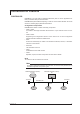
Introduction of Features PROFIBUS-DP PROFIBUS is an open field bus standard (IEC61158) used in various applications for factory automation and process automation. PROFIBUS-DP (Decentralized Periphery) is used for communication between PLCs and remote I/O, enabling high-speed data transmission. Configuration Components PROFIBUS-DP network consists of following components: • Class 1 master A controller to exchange information with the slave in a cyclic manner. This is a PLC or PC.
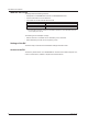
Introduction of Features What the DX Can Do The DX provides the following functions: • Participate in an PROFIBUS-DP network as a PROFIBUS-DP slave. • Communicate with a PLC from Siemens. • The master can access internal data of the DX. Data Access Measurement channel data Read Computation channel*1 data Read Communication input data*1*2 Write *1 This is an option (/M1 and /PM1). *2 Communication input data, if coded in a calculation expression in the computation channel, can be displayed on the DX.
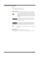
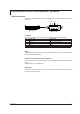
Connection to the PROFIBUS-DP Network Cable Connection Connect the PROFIBUS-DP cable to a PROFIBUS-DP connector provided on the back of the DX. 5 4 3 2 1 (Rear panel) 9 8 7 6 Connector D-sub 9-pin (female) connector. Each pin corresponds to the following signals. Pin Signal name 3 RxD/TxD - P 4 CNTR - P 5 DGND 6 VP + 5 V 8 RxD/TxD - N Pins 1, 2, 7, and 9 are not used. Explanation Positive data receive/transmit. RTS (for use by repeater). Ground. + 5 V. Negative data receive/transmit.
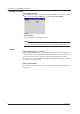
Connection to the PROFIBUS-DP Network Settings of the DX Node Address Settings Press MENU (to switch to setting mode), hold down FUNC for 3 s (to switch to basic setting mode), and select the Menu tab > Communication (PROFIBUS). • Node Address Set a node address in the range of 0 to 125. Note The node address of PROFIBUS-DP can be checked on the Network Information Screen of the DX. You can open the Network Information Screen by pressing FUNC > Network info softkey.
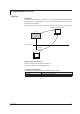
Preparation for PLC GSD File Installation To have the DX participate in a network, you must first install the DX device database file (GSD file) in the configuration tool. A PLC communicates with the DX based on the information in the GSD file. For information on using the configuration tool, see the configuration tool user's manual. PROFIBUS configuration tool PLC PROFIBU-DP GSD file DX How to Obtain the GSD File Obtain the GSD file from the Yokogawa Web site: URL: www.yokogawa.
Preparation for PLC Specification of Data If you install the GSD file, the DX is added to the configuration tool as a "General" type "Slave". Select [Model] to expand the module list and select your DX model from the list.
I/O Buffer and Data Mapping A master device such as a PLC accesses internal data of the DX via the "Input buffer" and "Output buffer" of the DX. "Input" represents an input to the master, while "Output" represents an output from the master. Mapping Method of the I/O buffer The "Input buffer" and "Output buffer" of the DX for PROFIBUS-DP communication has 128 bytes each. Data is laid out as described in the following table. Data layout cannot be changed.
I/O Buffer and Data Mapping Data Mapping Data mapping for each model is shown in the table. The following symbols are used in the table. Symbol Explanation CH1, CH2 Data of the measurement channel 1 or measurement channel 2. CH101, CH112 Data of the computation channel 101 or computation channel 112. C01, C24 Communication input data. INT16 16-bit signed integer. INT32_B 32-bit signed integer, BigEndian*. * BigEndian: Assuming that a value of 01020304H is located as 01 02 03 04 in the buffer.
I/O Buffer and Data Mapping Mapping of the output buffer Offset 0–3 4–7 8 – 11 12 – 15 16 – 19 20 – 23 24 – 27 28 – 31 32 – 35 36 – 39 40 – 43 44 – 47 48 – 51 52 – 55 56 – 59 60 – 63 64 – 67 68 – 71 72 – 75 76 – 79 80 – 83 84 – 87 88 – 91 92 – 95 96 – 127 Description C01 C02 C03 C04 C05 C06 C07 C08 C09 C10 C11 C12 C13 C14 C15 C16 C17 C18 C19 C20 C21 C22 C23 C24 Ignore anything that is written.
I/O Buffer and Data Mapping DX1006 Mapping of the input buffer Offset 0–1 2–3 4–5 6–7 8–9 10 – 11 12 – 15 16 – 19 20 – 23 24 – 27 28 – 31 32 – 35 36 – 39 40 – 43 44 – 47 48 – 51 52 – 55 56 – 59 60 – 63 64 – 67 68 – 71 72 – 75 76 – 79 80 – 83 84 – 87 88 – 91 92 – 95 96 – 99 100 – 103 104 – 107 108 – 127 Description CH1 CH2 CH3 CH4 CH5 CH6 CH101 CH102 CH103 CH104 CH105 CH106 CH107 CH108 CH109 CH110 CH111 CH112 CH113 CH114 CH115 CH116 CH117 CH118 CH119 CH120 CH121 CH122 CH123 CH124 Always 0.
I/O Buffer and Data Mapping DX1012 Mapping of the input buffer Offset 0–1 2–3 4–5 6–7 8–9 10 – 11 12 – 13 14 – 15 16 – 17 18 – 19 20 – 21 22 – 23 24 – 27 28 – 31 32 – 35 36 – 39 40 – 43 44 – 47 48 – 51 52 – 55 56 – 59 60 – 63 64 – 67 68 – 71 72 – 75 76 – 79 80 – 83 84 – 87 88 – 91 92 – 95 96 – 99 100 – 103 104 – 107 108 – 111 112 – 115 116 – 119 120 – 127 Description CH1 CH2 CH3 CH4 CH5 CH6 CH7 CH8 CH9 CH10 CH11 CH12 CH101 CH102 CH103 CH104 CH105 CH106 CH107 CH108 CH109 CH110 CH111 CH112 CH113 CH114 CH11
I/O Buffer and Data Mapping DX2004 Mapping of the input buffer Offset 0–1 2–3 4–5 6–7 8 – 11 12 – 15 16 – 19 20 – 23 24 – 27 28 – 31 32 – 35 36 – 39 40 – 43 44 – 47 48 – 51 52 – 55 56 – 127 Description CH1 CH2 CH3 CH4 CH101 CH102 CH103 CH104 CH105 CH106 CH107 CH108 CH109 CH110 CH111 CH112 Always 0.
I/O Buffer and Data Mapping DX2008 Mapping of the input buffer Offset 0–1 2–3 4–5 6–7 8–9 10 – 11 12 – 13 14 – 15 16 – 19 20 – 23 24 – 27 28 – 31 32 – 35 36 – 39 40 – 43 44 – 47 48 – 51 52 – 55 56 – 59 60 – 63 64 – 127 Description CH1 CH2 CH3 CH4 CH5 CH6 CH7 CH8 CH101 CH102 CH103 CH104 CH105 CH106 CH107 CH108 CH109 CH110 CH111 CH112 Always 0. Data type INT16 NT32_B - Mapping of the output buffer Same as for the mapping of the DX2004 output buffer.
I/O Buffer and Data Mapping DX2010 Mapping of the input buffer Offset 0–1 2–3 4–5 6–7 8–9 10 – 11 12 – 13 14 – 15 16 – 17 18 – 19 20 – 23 24 – 27 28 – 31 32 – 35 36 – 39 40 – 43 44 – 47 48 – 51 52 – 55 56 – 59 60 – 63 64 – 67 68 – 71 72 – 75 76 – 79 80 – 83 84 – 87 88 – 91 92 – 95 96 – 99 100 – 103 104 – 107 108 – 111 112 – 115 116 – 119 120 – 123 124 – 127 Description CH1 CH2 CH3 CH4 CH5 CH6 CH7 CH8 CH9 CH10 CH101 CH102 CH103 CH104 CH105 CH106 CH107 CH108 CH109 CH110 CH111 CH112 CH113 CH114 CH115 CH116
I/O Buffer and Data Mapping DX2020 Mapping of the input buffer] Offset 0–1 2–3 4–5 6–7 8–9 10 – 11 12 – 13 14 – 15 16 – 17 18 – 19 20 – 21 22 – 23 24 – 25 26 – 27 28 – 29 30 – 31 32 – 33 34 – 35 36 – 37 38 – 39 40 – 43 44 – 47 48 – 51 52 – 55 56 – 59 60 – 63 64 – 67 68 – 71 72 – 75 76 – 79 80 – 83 84 – 87 88 – 91 92 – 95 96 – 99 100 – 103 104 – 107 108 – 111 112 – 115 116 – 119 120 – 123 124 – 127 Description CH1 CH2 CH3 CH4 CH5 CH6 CH7 CH8 CH9 CH10 CH11 CH12 CH13 CH14 CH15 CH16 CH17 CH18 CH19 CH20 CH101
I/O Buffer and Data Mapping DX2030 Mapping of the input buffer Offset 0–1 2–3 4–5 6–7 8–9 10 – 11 12 – 13 14 – 15 16 – 17 18 – 19 20 – 21 22 – 23 24 – 25 26 – 27 28 – 29 30 – 31 32 – 33 34 – 35 36 – 37 38 – 39 40 – 41 42 – 43 44 – 45 46 – 47 48 – 49 50 – 51 52 – 53 54 – 55 56 – 57 58 – 59 60 – 63 64 – 67 68 – 71 72 – 75 76 – 79 80 – 83 84 – 87 88 – 91 92 – 95 96 – 99 100 – 103 104 – 107 108 – 111 112 – 115 116 – 119 120 – 123 124 – 127 Description CH1 CH2 CH3 CH4 CH5 CH6 CH7 CH8 CH9 CH10 CH11 CH12 CH13 C
I/O Buffer and Data Mapping DX2040 Mapping of the input buffer Offset 0–1 2–3 4–5 6–7 8–9 10 – 11 12 – 13 14 – 15 16 – 17 18 – 19 20 – 21 22 – 23 24 – 25 26 – 27 28 – 29 30 – 31 32 – 33 34 – 35 36 – 37 38 – 39 40 – 41 42 – 43 44 – 45 46 – 47 48 – 49 50 – 51 52 – 53 54 – 55 56 – 57 58 – 59 60 – 61 62 – 63 64 – 65 66 – 67 68 – 69 70 – 71 72 – 73 74 – 75 76 – 77 78 – 79 80 – 83 84 – 87 88 – 91 92 – 95 96 – 99 100 – 103 104 – 107 108 – 111 112 – 115 116 – 119 120 – 123 124 – 127 Description CH1 CH2 CH3 CH4 C
I/O Buffer and Data Mapping DX2048 Mapping of the input buffer Offset 0–1 2–3 4–5 6–7 8–9 10 – 11 12 – 13 14 – 15 16 – 17 18 – 19 20 – 21 22 – 23 24 – 25 26 – 27 28 – 29 30 – 31 32 – 33 34 – 35 36 – 37 38 – 39 40 – 41 42 – 43 44 – 45 46 – 47 48 – 49 50 – 51 52 – 53 54 – 55 56 – 57 58 – 59 60 – 61 62 – 63 64 – 65 66 – 67 68 – 69 70 – 71 72 – 73 74 – 75 76 – 77 78 – 79 80 – 81 82 – 83 84 – 85 86 – 87 88 – 89 90 – 91 92 – 93 94 – 95 96 – 99 100 – 103 104 – 107 108 – 111 112 – 115 116 – 119 120 – 123 124 – 12
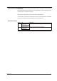
Specifications Basic Specifications Item Data mapping Node address Interface Transmission media Transmission rate/Transmission distance Terminator Specifications See "I/O Buffer and Data Mapping". 0 to 125 PROFIBUS-DP-V0 Slave Dedicated two-wire cable (two wire for the signal) 9.6 Kbps/1200 m to 12 Mbps/100 m Not built-in (External termination is required.) The DX data update interval The DX data is updated in a scan interval. However, it is not faster than 250 ms.
Index Index C cable.......................................................................................5, 7 cable connection.........................................................................7 class 1 master.............................................................................5 class 2 master.............................................................................5 communication input data.........................................................11 computation channel....................