User’s Manual Models D X1002/DX1004/DX1006/DX1012/ DX1002N/DX1004N/DX1006N/DX1012N Daqstation DX1000/DX1000N Operation Guide IM 04L41B01-02E 7th Edition
User Registration Thank you for purchasing YOKOGAWA products. We invite you to register your products in order to receive the most up to date product information. To register, visit the following URL. http://www.yokogawa.
Contents Safety Precautions......................................................................................................................................................4 Handling Precautions of the DX..................................................................................................................................5 Handling Precautions of the External Storage Medium (CF Card).............................................................................
Contents Operation.......................................................................................................................................................................39 Starting Memory Sampling.......................................................................................................................................39 Stopping Memory Sampling......................................................................................................................................
Thank you for purchasing the Daqstation DX1000/DX1000N (DX).This manual describes the basic operating procedures and installation and wiring procedures of the DX1000/DX1000N. To ensure correct use, please read this manual and the manuals below thoroughly before beginning operation. Paper Manual Manual Title Manual No. DX1000/DX1000N Operation Guide IM 04L41B01-02E This manual. It is also provided in the CD. Control of Pollution Caused by the Product IM 04L41B01-91C Gives a description of pollution control.
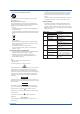
Safety Precautions • • WARNING This instrument conforms to IEC safety class I (provided with terminal for protective grounding), Installation Category II, and EN61326-1 (EMC standard), Measurement Category II (CAT II)*. * Measurement category II (CAT II) applies to measuring circuits connected to low voltage installation, and electrical instruments supplied with power from fixed equipment such as electric switchboards.
Handling Precautions of the DX • Use care when cleaning this instrument, especially its plastic parts. Use a soft dry cloth. Do not use organic solvents, such as benzene or thinner, or other cleansers. They may cause discoloring and deformation. • Keep electrically charged objects away from the signal terminals. If you do, the DX may malfunction. • Do not apply volatile chemicals to the display, panel keys, etc.
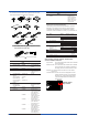
Standard Accessories The standard accessories below are supplied with the instrument. Check that all contents are present and undamaged. 1 2 3 32 B M /H5D 7 /H5F /H5R /H5J ID No. 9 Name 1 2 Qty.
Protection of Environment Opening the Electronic Manuals Control of Pollution Caused by the Product For details, see the Control of Pollution Caused by the Product (IM04L41B01-91C). Proper Disposal of This Product This is an explanation of how to dispose of this product based on Waste Electrical and Electronic Equipment (WEEE), Directive 2002/96/EC. This directive is only valid in the EU. • Marking This product complies with the WEEE Directive (2002/96/EC) marking requirement.
Introduction to Functions Measured Items You can connect DC voltage, thermocouple, RTD, and ON/OFF input and measure various values such as temperature and flow rate. The DX samples the input signals at the scan interval to obtain the measured values. The fastest scan interval is 25 ms on the DX1002, DX1002N, DX1004, and DX1004N and 125 ms on the DX1006, DX1006N, DX1012, and DX1012N. Up to four alarm conditions can be set for each measurement channel.
Introduction to Functions DX System Configuration The DX can be used to configure a system as shown below. Referenced sections are of the DX1000/DX1000N User’s Manual. Referenced pages are of this manual.
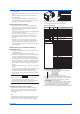
Names of Parts Front View Key panel opened LCD Display various operation displays such as the trend display as well as setup displays. Front cover (key panel) Open the front cover by pulling the cover while holding down the tab at the center of the upper section of the cover. Power indicator Illuminates in red when the power is turned ON. Illuminates in green while memory sampling is in progress.
Names of Parts Rear Panel Serial port (/C3 option) RS-422/485 port. Power supply terminals USB port (/USB1 option) A USB Rev. 1.1 compliant port. PROFIBUS-DP port (/CP1 option) PROFIBUS connector. Ethernet port A 10Base-T port. Serial port (/C2 option) RS-232 port. Optional terminals (/A[ ], /F1, /R1, /TPS[ ], and /PM1 options) Used to connect optional input/output signal wires. Input terminals (screw terminals or clamped terminals; /H2 option) Used to connect input signal.
DX1000/DX1000N Workflow When using the DX for the first time, carry out the following procedure. Installation Wiring Power ON Environmental Settings Install the DX. Page 49 and subsequent pages Connect input/output wires to the terminals and connectors on the rear panel, and connect the power cord. Page 52 and subsequent pages Turn the power ON. (DX1002, DX1004, DX1006, and DX1012 Only) Page 13 Set the date/time, load the CF card, and so on.
Turning the Power ON/OFF (DX1002, DX1004, DX1006, and DX1012 Only) Turning the Power ON CAUTION Before turning ON the power switch, check that • The power cord/wires are connected correctly to the DX. • The DX is connected to the correct power supply (see page 60). If the input wires are connected in parallel with other devices, do not turn ON/OFF the power switch of the DX or another device during operation. This can have adverse effects on the measured values. 1. Open the operation cover. 2.
Basic Operation Panel Keys LCD Key panel START STOP USER FUNC ESC MENU Soft keys Selects the menu that is displayed at the bottom of the screen. DISP/ENTER key and four arrow keys (up, down, left, and right) Switches the operation screen. Selects and enters setup items. DISP/ENTER key Up arrow key Right arrow key START STOP USER FUNC START/STOP key Memory start/stop. USER key Executes the assigned operation. ESC MENU ESC key Cancels an operation.
Basic Operation Display on the Status Display Section The following information is displayed in the status display section. Memory sampling status Memory sampling stopped Memory sampling in progress Memory sampling icon Data type DISP: Display data EVENT: Event data Memory sampling progress Displays the progress using a green bar graph. The frame indicates the file save interval (display data) or the data length (event data). Error in internal memory. Contact your nearest YOKOGAWA dealer for repairs.
Basic Operation Run Modes Mode Transition Diagram Power ON Operation mode Setting mode Basic setting mode End menu > DISP/ENTER or ESC > DISP/ENTER (release number 3 or later) MENU key Setting menu display Operation display MENU key or ESC key On a DX with advanced security (/AS1 option; release number 4 or later): MENU key or ESC key > DISP/ENTER or End menu > DISP/ENTER DISP/ENTER key MENU key or ESC key Setup display Hold down FUNC for 3 s or Basic Setting Mode > DISP/ENTER (release number 3
Basic Operation Entering Values and Characters The character/number input window and DISP/ENTER key are used to set the date/time, set the display span of the input range, set the tag, set the message string, enter the password, etc. Character/number input window Cursor DISP/ENTER key and four arrow keys (up, down, left, and right) Text box for entering the character string Select the character.
Basic Operation The contents of the screens in the operation examples below may change depending on which options are installed and how the settings are configured. On a DX with advanced security (/AS1 option; release number 4 or later) you must first insert the CF card into the slot (see page 24). Changing the Date/Time In this example, we will change the date from the 1st to the 6th. After carrying out this step, reset the time to the correct date/time. 1. Display the operation mode screen. 2.
Basic Operation 7. Press ESC twice or MENU once to return to the operation mode screen. On a DX with advanced security (/AS1 option; release number 4 or later): Press ESC twice or MENU once to display a confirmation screen. To return to the operation mode screen, select Yes, and press DISP/ENTER once. Operation complete. Operation Example in the Setting Mode: Changing the Input Range Set the input range of channel 2 to thermocouple type T and 0.0 to 400.0°C. DX Type T thermocouple Channel 2 1.
Basic Operation 5. Press DISP/ENTER once. Select First-CH. 6. Press the +1 soft key once to set First-CH and Last-CH to 2. 7. Press the down arrow key once to move the cursor to Mode. 8. Press the TC soft key once. The cursor moves to Range, and the changed item is displayed in yellow. Select TC. 9. Press the Next soft key. 10. Press the T soft key once. The cursor moves to Span_L. 11. Press the Input soft key once. Display the Span_L setting window. 12. Enter 0.
Basic Operation 14. Press DISP/ENTER once. The changed items are entered, and the cursor returns to First-CH. The changed items change from yellow to white. 15. Press ESC three times or MENU twice to return to the operation mode screen. On a DX with advanced security (/AS1 option; release number 4 or later): Press ESC three times or MENU twice to display a confirmation screen. To return to the operation mode screen, select Yes, and press DISP/ENTER once. Operation complete.
Basic Operation Operation Example in the Basic Setting Mode: Changing the Scan Interval In this example, we will change the scan interval. Here, the scan interval on the DX1012 is changed to 2 s. The selectable scan intervals are different on the model, but the procedure is the same. Measures every 2 s Type T thermocouple DX Channel 2 1. Display the operation mode screen. 2. Press MENU once to display the setting menu. 3. Hold down FUNC for at least 3 s.
Basic Operation 4. Press the down arrow key twice to select A/D, Memory. 5. Press DISP/ENTER once. 6. Press the down arrow key once to move the cursor to Scan interval. 7. Press the 2s soft key once. The cursor moves to A/D integrate, and the changed item is displayed in yellow. Cancel the setting: Press ESC before pressing DISP/ENTER. 8. Press DISP/ENTER once. The changed items are entered, and the cursor returns to Scan mode. Set the scan interval to 2 s. 9.
Basic Operation Inserting/Removing a CF Card Inserting a CF Card 1. Open the operation cover. CAUTION Forcing the CF card into the slot with the upside down may cause damage. T h is id s e u p CF card With the label “This side up” facing up 2. Insert the CF card into the slot. Displays the CF card icon If the DX does not recognize the CF card, try reinserting it. 3. Close the operation cover. Operation complete. Removing a CF Card 1. Press FUNC once.
Basic Operation 5. Press the CF card eject button. When you eject the CF card, the CF card icon disappears. Press the eject button in until it clicks. The eject button stops at depressed position. Pinch the left and right sides of the CF card and remove it. Eject button 6. Close the operation cover. Operation complete. 1.
Basic Operation Saving the Setup Data In this example, we will save the setup data to a file named “SF2” on the CF card. 1. Display the operation mode screen. 2. Press MENU once to display the setting menu. 3. Press the right arrow key once to select the File tab. 4. Press the down arrow key four times. Select Save settings. 5. Press DISP/ENTER once. 6. Press the Input soft key once. 7. Enter “SF2” for the file name.
Basic Operation Loading the Setup Data In this example, we will load the setup data “SF2” from the CF card and update the DX settings. This procedure only loads the setup data that the DX uses for setting mode.To load the setup data for both setting mode and basic setting mode, press MENU, hold down FUNC for 3 s, select the File/Initialize tab > Load settings, and press DISP/ENTER. 1. Display the operation mode screen. 2. Press MENU once to display the setting menu. 3.
Setting the Input Range and Alarm Setup Example 1: Temperature Measurement Channel DX Type T thermocouple Channel 1 0.0 to 200.0°C Setup Item Channel Tag Sensor Input range Description Use channel 1. TI-001 Type T thermocouple 0.0 to 200.0°C Number in the Figure 1 2 3 4 (1) Input Range Press MENU (switch to the setting mode). Select the Menu tab > Meas channel > Range, Alarm. 1 4 3 (2) Tag Select the Menu tab > Meas channel > Tag, Memory, Delay. 2 Operation complete.
Setting the Input Range and Alarm Setup Example 2: Flow Rate Measurement Channel and Alarm DX Flowmeter Channel 2 4 - 20 mA Convert to 1-5 V with a shunt resistor Setup Item Channel Tag Input signal Input range Alarm condition Description Use channel 2. FI-002 1-5V 0.0 to 500.0 L/H Output an alarm if the measured value is less than or equal to 120.0 L/H. Output destination: Relay contact (I03) Number in the Figure 1 2 3 4 5 (1) Input Range and Alarm Press MENU (switch to the setting mode).
Setting the Display Setup Example 3: Assigning Channels to Groups In this example, we will assign channels 1 and 2 to group 1. Group 1 Channel 1 Setup Item Group Channel 2 Description Assign channel 1 and 2 to group 1. Number in the Figure 1 (1) Group Press MENU (to switch to setting mode) > select the Menu tab > Group set, Trip line. 1 Operation complete.
Setting the Display Setup Example 4: Setting the Time Scale Set the time per division of the trend waveform to 2 minutes. The sampling interval (the time corresponding to 1 dot) is 4 s when the trend interval is 2 min. 30 dots × 4 s = 2 min 30 dots/div Setup Item Trend interval Description Set the time per division to 2 minutes. The waveform is updated at every 4 s.
Setting the Data Storage Setup Example 5: Continuously Record Measured Data and Automatically Save In this example, we will continuously record and save the measured data of channel 1 and 2. For the procedure to set the channel, see “Setting the Input Range and Alarm” on page 28. For the procedure to set groups, see “Setting the Display” on page 30. Automatically save to the CF card periodically.
Setting the Data Storage (2) Method of Storing to the CF Card (Auto Save ON/OFF) Select the Environment tab > Security, Media save 3 (3) Save the Settings 1. Press ESC to return to the basic setting menu. 2. Press ESC once more. The window appears for you to confirm the saving of the settings. 3. Select Yes and press DISP/ENTER. The DX returns to the operation mode screen. (4) Channels to Be Recorded Press MENU (switch to the setting mode).
Setting the Data Storage (7) Save Destination Directory (within the CF Card) Select the Menu tab > Data save > Save directory. 6 Operation complete.
Setting the Data Storage Setup Example 6: Saving Measured Data at the Specified Time Using the settings of Setup Example 5, we will save the measured data once at hour 0 every day. Every hour 0 DX 10 11 12 1 9 8 2 3 7 6 5 4 Automatically save to the CF card All settings other than those listed below are the same as Setup Example 5. Setup Item Data storage time Data storage method Description Save the data once at hour 0 every day. Automatically save the measured data at the specified time.
Customizing the Operation Setup Example 7: Assigning the Screen Image Data Storage Function to the USER Key In this example, we will set the DX so that the displayed screen image data can be saved to the CF card by pressing the USER key. This function is called snapshot. The extension of snapshot data files is .png. START STOP USER FUNC ESC MENU USER key Setup Item Event action Description Save the screen image data of the DX using the USER key.
Customizing the Operation Setup Example 8: Registering Frequently Used Screens to the Favorite Key Up to eight operation mode screens that are frequently used can be registered to the Favorite key. This enables you to monitor the operation by using only the Favorite key. This feature is convenient when comparing data such as historical trends.
Customizing the Operation 5. Press the favorite number (1 to 8) soft key. 6. Press the Regist soft key. Show the window for entering the display name. 7. Enter the screen name. Select the input position: Left and right arrow soft keys Enter characters: Arrow keys and DISP/ENTER Delete a character: Use the arrow keys to select Del and press DISP/ENTER, or press the Bs soft key. Enter the input: Use the arrow keys to select ENT and press DISP/ENTER.
Operation Starting Memory Sampling 1. Press START once. On a DX with advanced security (/AS1 option; release number 4 or later) display the start * recording screen . With START selected, press DISP/ENTER once. Memory sampling starts. * This is because the Batch function is enabled upon shipment from the factory. Recording data Memory sampling progress DISP: Display data EVENT: Event data START STOP USER FUNC ESC MENU START key Operation complete. Stopping Memory Sampling 1.
Operation Switching the Trend Display, Digital Display, and Bar Graph Display 1. Press DISP/ENTER once to show the display selection menu. Left arrow key Up arrow key Right arrow key DISP/ENTER key Down arrow key 2. Press the down arrow key to select TREND, DIGITAL, or BAR. 3. Press the right arrow key once to display the sub menu. To close the sub menu that you opened, press the left arrow key. 4. Press the down arrow key to select the group. Select DIGITAL > GROUP 1. 5.
Operation Writing the Message “START” Registering the Word “START” in Message Number 1 On a DX with advanced security (/AS1 option; release number 4 or later), this operation is only available when memory sampling is stopped. 1. Press MENU (to switch to setting mode) > select the Menu tab > Message, Comment > Message > DISP/ENTER. 2. Press the 1-10 soft key. The message, “Message numbers 1-10 can also be used for free message” appears. Press DISP/ENTER. 3. Press the down arrow key.
Operation Writing Message Number 1 “START” This operation can only be carried out while memory sampling is in progress. The message is displayed on the trend display. Show the trend display first. 1. Press FUNC (display the FUNC key menu), press the Message soft key, and press the 1-10 soft key. Show the message registration window. 1 soft key 2. Press the 1 soft key. Shows the message. (time, message, and message mark) Also recorded to the internal memory. Operation complete.
Connecting to an Ethernet Network Setup Example 9: Monitoring the DX on a PC Browser In this example, we will connect the PC and the DX via hub in a one-to-one relationship and display and monitor the DX screen on a browser on the PC. PC HUB Ethernet DX DX Setup Item IP address Subnet mask Web server function Access to the DX PC Setup Item IP address Subnet mask Description 192.168.1.101 255.255.255.0 Monitor from a Web browser on the PC using operator page.
Connecting to an Ethernet Network (2) Enabling the Web Server Function on the DX Select the Menu tab > Communication (Ethernet) > Server > Server. 2 (3) Display the DX Screen on the PC Select the Menu tab > Communication (Ethernet) > Web page. 2 3 (4) Save the Settings 1. Press ESC twice to return to the basic setting menu. 2. Press ESC once more. The window appears for you to confirm the saving of the settings. 3. Select Yes and press DISP/ENTER.
Connecting to an Ethernet Network (6) Checking the Connection Send the command below from the PC and check that a correct response is returned. Send >ping 192.168.1.101 Response example >Reply from 192.168.1.101: bytes=32 time<10ms TTL=255 (7) Displaying the DX Screen on the Browser 1. Start the browser on the PC. 2. Enter the following URL. http://192.168.1.101/operator.htm 3. Check that the DX screen appears. Operation complete.
Connecting to an Ethernet Network Setup Example 10: Automatically Transferring the Measured Data File to an FTP Server In this example, we will configure the DX so that the measured data is automatically transferred to an FTP server on the network when the measured data is automatically saved to the CF card. To automatically transfer the measured data files and report files, the auto saving of the measured data must be configured in advance (“Data storage method” of Example 5).
Connecting to an Ethernet Network (3) Data to Be Transferred to the FTP Server Select the Menu tab > Communication (Ethernet) > FTP client > FTP transfer file. 3 (4) Connected setting FTP Server Select the Menu tab > Communication (Ethernet) > FTP client > FTP connection. 4 Installation and Wiring (5) Save the Settings 1. Press ESC three times to return to the basic setting menu. 2. Press ESC once more. The window appears for you to confirm the saving of the settings. 3.
Using DAQSTANDARD Displaying the Measured Data on DAQSTANDARD In this example, we will display the measured data using the accompanying software program, DAQSTANDARD. 1. Insert the CF card containing the measured data file into the PC that has DAQSTANDARD installed. 2. Start DAQSTANDARD Viewer. 3. From the File menu, choose Open. 4. In the Open dialog box, select the desired file, and click Open. The data is displayed. Operation complete.
Installation and Wiring Installation Location Install the DX indoors in a location that meets the following conditions. • Instrumentation Panel The DX is designed to be installed in an instrumentation panel except for the desktop type. • Well-Ventilated Location To prevent overheating, install the DX in a well-ventilated location. For the panel cut dimensions when arranging multiple DXs, see the page 51.
Installation and Wiring Installation Procedure Installation Procedure (Panel Mount Type) Use a steel panel of thickness 2 mm to 26 mm. 1. Insert DX from the front of the panel. 2. Mount the DX to the panel using the mounting brackets that come with the package as shown in the figure below. • Use two brackets to support the top and bottom or the left and right sides of the case (remove the seal that is covering the holes for the mounting brackets beforehand).
Installation and Wiring External Dimensions and Panel Cut Dimensions Unit: mm (approx. inch) Unless otherwise specified, tolerance is ±3% (however, tolerance is ± 0.3 mm when below 10 mm). 136.5 +0.4 0 (5.37) Panel mount type MAX *1 (/H2 or /PM1) Side-by-Side Mounting (horizontally) 137 +20 (5.39) (Dimensions after attaching the mounting bracket) Side-by-Side Mounting (vertically, max. 3 units) 137+20 (5.39) 175 MIN (6.89) 137+20 (5.39) 137+20 (5.39) L+20 L+20 +2 L0 282 (11.10) 426 (16.
Installation and Wiring Input Signal Wiring WARNING • To prevent electric shock while wiring, ensure that the power supply source is turned OFF. CAUTION • If a strong tension is applied to the cable wired to the DX, the terminals of the DX and/or the cable can be damaged. In order to prevent tension from being applied directly on the terminals, fasten all wiring cables to the rear of the mounting panel. • To prevent fire, use signal wires having a temperature rating of 70°C or more.
Installation and Wiring Wiring Procedure A terminal cover is screwed in place on the measuring input terminal block on the rear panel. A label indicating the terminal arrangement is affixed to the cover. 1. Turn OFF the DX and remove the terminal cover. 2. Connect the signal wires to the terminals. Recommended torque for tightening the screws Screw terminals Clampted terminals 0.9 to 1.0 N•m 0.22 to 0.25 N•m 3. Replace the terminal cover and fasten it with screws.
Installation and Wiring Wiring Screw Terminals TC input DC voltage input/DI (ON/OFF) input Compensating leadwire + + + DC voltage input – – – RTD input DC current input b + A B B + DC current input A b – – Shunt resistor Example: For 4 to 20 mA input, use a shunt resistor of 250 Ω ± 0.1%. Lead wire resistance per wire of 10 Ω or less. Make the resistance of the three wires equal.
Installation and Wiring Optional Terminal Wiring WARNING • To prevent electric shock while wiring, ensure that the power supply source is turned OFF. • If a voltage of more than 30 VAC or 60 VDC is to be applied to the output terminals, use ring-tongue crimp-on lugs with insulation sleeves on all terminals to prevent the wires from slipping out when the screws become loose.
Installation and Wiring Arrangement of the Optional Terminals Optional terminal block NC Symbols such as “NC”: Terminal functions Alarm output, FAIL, Status NC: Normally closed C: Common NO: Normally opened See page 58. Remote control input 1 to 8: Terminal number C: Common See page 58. Transmitter power supply + and –: See page 58. Pulse input H and L: See page 58. A terminal that is not used. (With a screw) A terminal that is not used.
Installation and Wiring (From previous page) /F1 /R1 Status FAIL /A1 /PM1 Alarm output Remote control input NC NC 6 3 C C 7 4 NO NO 8 5 02 C H H H 3 C 1 C C L 1 2 NO NO 02 01 8 NC H H H 3 C C C L 4 NO NO NO 5 2 + + - - + + - - 7 L NO /A1 /TPS2 Alarm output 02 01 NC NC C C NO NO /TPS2 L 4 2 L Remote control input 8 7 6 C H H H 3 C 1 L 1 L L 4 5 Transmitter power supply + + - - Transmitter power supply + + - - Remote control input
Installation and Wiring Alarm Output Terminal (/A1, /A2, and /A3), FAIL Output Terminal, and Status Output Terminal (/F1) Output format: Contact rating: Relay contact FAIL 250 VAC (50/60 Hz)/3 A, output 250 VDC/0.
Installation and Wiring Connecting to the RS-422/485 (/C3) Four-wire system FG SG SDB SDA RDB RDA Two-wire system FG SG SDB SDA RDB RDA FG (Frame Ground) SG (Signal Ground) SDB (Send Data B) SDA (Send Data A) RDB (Received Data B) RDA (Received Data A) Frame ground of the DX. Signal ground. Send data B (+). Send data A (–). Receive data B (+). Receive data A (–). Shield Electric potential of the shield Recommended length of stripped wire: 9 mm. Recommended tightening torque: 0.4-0.
Installation and Wiring Power Supply Wiring Panel Mount Type, or Desktop Type with /P1 (Models with /H5 and /P1 Options) Precautions to Be Taken While Wiring the Power Supply Make sure to follow the warnings below when wiring the power supply. To prevent electric shock and damage to the DX, observe the following warnings. WARNING • To prevent electric shock when wiring, ensure the main power supply is turned OFF.
Installation and Wiring Desktop Type (/H5[ ] Option) Precautions to Be Taken While Connecting the Power Supply Make sure to follow the warnings below when connecting the power supply. To prevent electric shock and damage to the DX, observe the following warnings. WARNING • Before connecting the power cord, ensure that the source voltage matches the rated supply voltage of the DX and that it is within the maximum rated voltage range of the provided power cord.
Recommended Replacement Periods for Worn Parts To preserve the reliability of the DX and to use the DX in a good condition for an extended time, it is recommended that periodic replacements be made on parts. The replacement parts may change to accommodate preventive maintenance over extended time. Be sure to check with your nearest YOKOGAWA dealer. The following table shows the recommended replacement period for expendable parts.
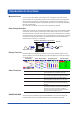
Setup Items and Default Values The setup items and the default values in the setting mode are listed below. Enter the settings that you are using in the Setting column for your convenience.
Setup Items and Default Values Basic setting mode menu Page 77 Page 77 Page 77 Page 77 Page 77*1 Page 78 Page 78 Page 78 Page 78*1 Page 79*1 Page 79 Page 80 Page 80 Page 80 Page 81*2 Page 81*2 Page 83*1 Page 83 Page 84 to 87 Page 88*1 Page 89*1 Page 89 Page 89 Communication (PROFIBUS-DP): For models with thePROFIBUS-DP interface (/CP1 option). Signature: For models with the Advanced Security (/CP1 option). Page 88*1 Page 80*1 Page 90 Page 90 Page 90 Page 90 *1: Optional.
Setup Items and Default Values Setup Items in Setting Mode and Their Default Values This section uses the following notations in tables. *1: This indicates functions that are available for release number 2 or later. *2: This indicates functions that are available for release number 3 or later. *3: This indicates functions that are available for release number 4 or later.
Setup Items and Default Values Setup Item Mode=DI Range Span Lower Span Upper Mode=1-5V Range Span Lower Span Upper Scale Lower Scale Upper Unit Low-cut Mode=Sqrt Range Span Lower Span Upper Scale Lower Scale Upper Unit Low-cut Low-cut value Alarm 1, 2, 3, 4 Type Value Relay Number Detect Selectable Range or Selections Default Value Level/Cont 0, 1 0, 1 Level 0 1 1-5V 0.800 to 5.200 0.800 to 5.
Setup Items and Default Values Meas channel > Color Setup Item Group of channel Color Selectable Range or Selections 001-006, etc Red/Green/Blue/B.violet/Brown/Orange/ Y.green/Lightblue/Violet/Graly/Lime/Cyan/ Darkblue/Yellow/Lightgray/Purple/Black/Pink/ L.brown/L.green/Darkgray/Olive/DarkCyan/ S.green (24 colors) Default Value Depends on the model.
Setup Items and Default Values Math channel > Expression, Alarm Setup Item First-CH, Last-CH Math On/Off Calculation expression Span Lower Span Upper Unit Math alarm 1, 2, 3, 4 Type Value Relay No. Detect Selectable Range or Selections Channel number On/Off 120 characters or less –9999999 to 99999999, decimal position: 0 to 4 –9999999 to 99999999, decimal position: 0 to 4 6 characters or less Default Value 101 Off – –200.00 200.
Setup Items and Default Values Math channel > Partial Setup items and values are the same as those for measurement channels, except the channel numbers. Math channel > Alarm mark Setup items and values are the same as those for measurement channels, except the channel numbers. Math channel > Color scale band Setup items and values are the same as those for measurement channels, except the channel numbers.
Setup Items and Default Values Display > Trend/Save interval Setup Item Trend interval [/div] Save interval Second interval [/div] Selectable Range or Selections *2 *2 5s /10s /15s/30s/1min/2min/5min/10min/ 15min/20min/30min/1h/2h/4h/10h (Depends on the model.) 10min to 31day (Depends on the trend interval.) *2 *2 5s /10s /15s/30s/1min/2min/5min/10min/ 15min/20min/30min/1h/2h/4h/10h (Depends on the model.
Setup Items and Default Values Group set, Trip line Setup Item Group number Group set > On/Off Selectable Range or Selections 1/2/3/.../9/10 On/Off Group set > Group name Group set > CH set Trip line 1, 2, 3, 4 Position Color 16 characters or less 39 characters or less On/Off 0 to 100 Red/Green/.../S.green (24 colors) 1/2/3 Width Default Value 1 Group 1 to 4: On Group 5 to 10: Off GROUP1 etc. Depends on the model.
Setup Items and Default Values Timer, Event action > Event action Setup Item Logic box number Event Remote > Remote number Relay > Relay number Switch > Switch No. Timer > Timer No. MatchTimeTimer > Match Time Timer No. *2 EventLevelSwitch > Event Switch No *2 EventEdgeSwitch > Event Switch No *3 Relay-Off > Relay number * Switch-Off > Switch No. EventLevelSwitch-Off > Event Switch *3 No 72 Selectable Range or Selections 1/2/3/...
Setup Items and Default Values Setup Item Action Message > Message No. Message > Write to Message > Group number Group > Group numbe *2 FavoriteDisplay > Action FavoriteDisplay > Select *2 > Favorite Screen No CommentDisplay *2 > Comment Txt Block No Flag > Flag number TimerReset > Timer No.
Setup Items and Default Values Data save > File header, File name Setup Item File header > Characters Data file name > Structure Data file name > Identified strings Selectable Range or Selections 50 characters or less Date/Serial/Batch 16 characters or less Default Value – Date – Setting Selectable Range or Selections 20 characters or less Default Value DATA0 Setting Data save > Save directory Setup Item Directory name Data save > Event data Setup Item Without /AS1 Sample rate Selectable Range or
Setup Items and Default Values *2 Multi batch tab *2 Group set, Trip line > Group set Setup Item First Batch Group, Last Batch Group Display Group No Set Display Group > On/Off Set Display Group > Group name Set Display Group > CH set Selectable Range or Selections 1/2/3/4/5/6 (varies depending on settings) 1/2/3/4/5/6 On/Off 16 characters or less 23 characters or less Default Value 1 1 Off BATCH-1, etc. Depends on the model.
Setup Items and Default Values Load event data Setup Item Kind Selectable Range or Selections CF/USB Default Value CF Setting Selectable Range or Selections CF/USB Default Value CF Setting Selectable Range or Selections CF/USB 32 characters or less Default Value CF – Setting Selectable Range or Selections Internal 1 to Internal 3, External 1 to External 25 – Default Value Internal 1 – Setting Selectable Range or Selections – Default Value – Setting Selectable Range or Selections Internal 1
Setup Items and Default Values Setup Items in Basic Setting Mode and Their Default Values This section uses the following notations in tables. *1: This indicates functions that are available for release number 2 or later. *2: This indicates functions that are available for release number 3 or later. *3: This indicates functions that are available for release number 4 or later.
Setup Items and Default Values Security, Media save Setup Item Selectable Range or Selections Without /AS1 Security > Key Off/Login/Keylock Security > Communication Off/Login Save > Auto save On/Off *1 Save > Media FIFO On/Off *3 With /AS1 Security > Key Login Security > Communication Off/Login Security > Multi login On/Off Security > Password management On/Off The Save items are the same as on a DX without the /AS1 option.
Setup Items and Default Values Report Setup Item Report select > 1 Report select > 2 Report select > 3 Report select > 4 File type *3 Use Template Selectable Range or Selections Max/Min/Ave/Sum/Inst Off/Max/Min/Ave/Sum/Inst Off/Max/Min/Ave/Sum/Inst Off/Max/Min/Ave/Sum/Inst *3 Separate/Combine/Separate2 Use/Not Default Value Ave Max Min Sum Separate Not Setting End Setup Item Do you want to store and make the new settings take effect? Selectable Range or Selections Yes/No/Cancel Default Value – Setti
Setup Items and Default Values *2 Menu tab Alarm > Basic settings Setup Item Reflash Rate of change > Decrease Rate of change > Increase Indicator Selectable Range or Selections *3 *3 On/Off/On-1s /On-2s 1 to 32 1 to 32 Hold/Nonhold Default Value Off 1 1 Nonhold Setting Selectable Range or Selections None/S01/S01-S02/.../S01-S29/S01-S30 None/I01/I01-I02/.../I01-I06 (Depends on the option.
Setup Items and Default Values Keylock > Password, Key action, Media (Without /AS1) Setup Item Password Key action > START Key action > STOP Key action > MENU Key action > USER Key action > DISP/ENTER Key action > FAVORITE Media/USB > External media *2 Media/USB > Load settings Selectable Range or Selections 8 characters or less Free/Lock Free/Lock Free/Lock Free/Lock Free/Lock Free/Lock Free/Lock Free/Lock Default Value – Free Free Free Free Free Free Free Free Setting Selectable Range or Selections F
Setup Items and Default Values Login > User settings Setup Item Without /AS1 User number Mode User name Password Authority of user *3 With /AS1 User number Mode User name User ID Password Password expire Authority of user Selectable Range or Selections Default Value 1 to 30 Off/Key/Comm/Web/Key+Comm 20 characters or less *3 20 characters or less Off/1/2/3/4/5/6/7/8/9/10 1 Off User1 etc.
Setup Items and Default Values Report > Basic settings Setup Item Report kind Date Day of the week (Day+week) Time (hour) Selectable Range or Selections Off/Hour/Day/Hour+Day/Day+Week/Day+Month 1 to 28 SUN/MON/TUE/WED/THU/FRI/SAT 0 to 23 Default Value Off 1 SUN 0:00 Setting Setup Item Report channel number On/Off Selectable Range or Selections R01/R02/R03/.../R23/R24 On/Off Setting Channel Sum scale Channel number Off, /s, /min, /h, /day Default Value R01 Depends on the model 001 etc.
Setup Items and Default Values Communication (Ethernet) > IP-address Setup Item DHCP DNS accession Host-name register Fixed IP-address > IP-address Fixed IP-address > Subnet mask Fixed IP-address > Default gateway Selectable Range or Selections Use/Not Use/Not Use/Not 0.0.0.0 to 255.255.255.255 0.0.0.0 to 255.255.255.255 0.0.0.0 to 255.255.255.255 Default Value Not Use Use 0.0.0.0 0.0.0.0 0.0.0.0 Setting Default Value – – Setting Default Value 0.0.0.0 0.0.0.
Setup Items and Default Values Communication (Ethernet) > Web page Setup Item Selectable Range or Selections Default Value Without /AS1 Page type Operator/Monitor Operator Page type=Operator Web page > On/Off On/Off Off Web page > Access control Off/Admin Off Web page > Command Use/Not Not Page type=Monitor Web page > On/Off On/Off Off Web page > Access control Off/Admin/User Off *3 With /AS1 Page type Operator/Monitor Operator Page type=Operator Web page > On/Off On/Off Off Web page > Access control Off/A
Setup Items and Default Values Communication (Ethernet) > E-Mail > Scheduled settings Setup Item Recipient 1 Interval Ref.time Recipient 2 Interval Ref.
Setup Items and Default Values Communication (Ethernet) > FTP client > FTP connection Setup Item FTP connection FTP server name Port number Login name Password Account PASV mode Initial path Selectable Range or Selections Primary/Secondary 64 characters or less 0 to 65535 32 characters or less 32 characters or less 32 characters or less On/Off 64 characters or less Default Value Primary – 21 – ******...
Setup Items and Default Values *3 Communication (Ethernet) > Password management > Certification key (/AS1 option) Setup Item Host principal Realm name Password Encryption Selectable Range or Selections 20 characters or less 64 characters or less 20 characters or less AES128/AES256/ARC4 Default Value – – – AES128 Setting Communication (Serial) > Basic settings Setup Item Selectable Range or Selections Default Value Setting Without /AS1 Baud rate 1200/2400/4800/9600/19200/38400 9600 Data length 7/8 8 Pa
Setup Items and Default Values Status relay *3 Setup Item Without /AS1 Fail relay Status relay With /AS1 Fail relay Status relay Selectable Range or Selections Default Value Fail/Status relay Fail/Status relay Fail Status relay Fail/Status relay/Mem. sample/Invalid user/Login Fail/Status relay/Mem.
Setup Items and Default Values *2 File/Initialize tab Load settings Setup Item Without /AS1 Load settings > Kind Initialize > Kind Media eject *3 With /AS1 Load settings > All settings > Kind Load settings > Login info only > Kind Load settings > Other settings > Kind Initialize > Kind Media eject Selectable Range or Selections Default Value CF/USB Clear 1/Clear 2/Clear 3 CF/USB CF Clear 3 – CF/USB CF/USB CF/USB Clear 1/Clear 2/Clear 3/Clear 4 CF/USB CF CF CF Clear 3 – Selectable Range or Selection