Service Manual Daqstation DX1000/DX1000N/DX2000 SM 04L41B01-01E Yokogawa Electric Corporation 4th Edition
Important Notice to the User • This manual contains information for servicing YOKOGAWA’s DX1000, DX1000N, and DX2000. Check the serial number to confirm that this is the correct service manual for the instrument to be serviced. Do not use the wrong manual. • Before any maintenance and servicing, read all safety precautions carefully. • Only properly trained personnel may carry out the maintenance and servicing described in this service manual.
Introduction This manual contains information for servicing YOKOGAWA’s DX1000, DX1000N, and DX2000. WARNING This service manual is to be used by properly trained personnel only. To avoid personal injury, do not perform any servicing unless you are qualified to do so. Refer to the safety precautions prior to performing any servicing. Even if servicing is carried out according to this service manual, or by qualified personnel, YOKOGAWA assumes no responsibility for any result occurring from that servicing.
• Do Not Operate in an Explosive Atmosphere Do not operate the instrument in the presence of flammable liquids or vapors. Operation in such an environment constitutes a safety hazard. Prolonged use in a highly dense corrosive gas (H2S, SOx, etc.) will cause a malfunction. • Do Not Remove Covers The cover should be removed by YOKOGAWA’s qualified personnel only. Opening the cover is dangerous, because some areas inside the instrument have high voltages.
Overview of This Manual This manual is meant to be used by qualified personnel only. Make sure to read the safety precautions at the beginning of this manual as well as the warnings and cautions contained in the chapters relevant to any servicing you may be carrying out. This manual contains the following chapters. Chapter 1 Principles of Operation Describes the principles of operation of the instrument. Chapter 2 Troubleshooting Lists problems that can occur and gives corrective actions.
Contents 1 Important Notice to the User...............................................................................................................i Trademark...........................................................................................................................................i Revisions............................................................................................................................................i Introduction.............................................
Contents Chapter 6 Chapter 7 Customer Maintenance Parts List 6.1 6.2 6.3 Replacing Parts 7.1 7.2 7.3 vi Customer Maintenance Parts List (DX1000)........................................................................ 6-1 Customer Maintenance Parts List (DX1000N).................................................................... 6-10 Customer Maintenance Parts List (DX2000)...................................................................... 6-20 Introduction......................................
Chapter 1 Principles of Operation 1.1 Principles of Operation 1 Principles of Operation The following explains the principles of operation of the DX.
1.1 Principles of Operation Saving Data The capacity of the internal memory is either 80 MB (standard memory) or 200 MB (expansion memory). The CF card can be used as an external memory medium. Display/Keys/Easy Text Entry The DX uses an LCD display. You can control the DX with key operations. With Easy Text Entry (optional), you can control input by the remote control terminal.
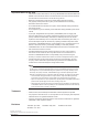
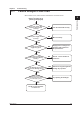
Chapter 2 Troubleshooting 2.1 Failure Analysis Flow Chart 1 When a failure occurs, refer to the flow chart below for corrective actions. 2 Troubleshooting Doesn’t function at all (nothing is displayed) 3 Is the power switch* ON? Does the switch operate normally? NO Turn the switch ON correctly. 4 YES Is the power supply wired correctly? NO 5 Wire it correctly.
2.1 Failure Analysis Flow Chart Keys do not operate correctly Is the key lock set? YES Release the key lock setting. NO See No. 4 of the checklist. If there is a problem with a display screen or other function Have measures against external noise been taken? NO YES See No. 2, 3, 7, 9, and 10 of the checklist in section 2.2. • Keep measurement input, communication, and other wires and cables away from noise sources. • Be sure to ground all instruments.
2.
2.2 Troubleshooting Checklist The table below describes the most common types of failures and their corrective actions. Action Replace Adjust Check No. Phenomenon Refer to Chapter 6 Description Part Name *1 1 2 The instrument doesn’t start even though the power is ON FAIL state Power supply cable connection/wiring 4 5 6-23 6-23 6 18 SUB BOARD ASSEMBLY Sub PBA EXP.
2.2 Troubleshooting Checklist 1 Action Replace Adjust Check No. Phenomenon Refer to Chapter 6 Description Part Name *1 8 External media functioning abnormally 9 Abnormal communication USB operation 10 abnormal - - - - - - - - - - - - - - MEDIA BOARD ASSEMBLY CF Assembly 6-4 26 - - 6-23 45 SUB BOARD ASSEMBLY Sub PBA EXP.
Chapter 3 3.1 Testing Acceptance Test 1 This section describes the procedure to perform the acceptance test. 2 1. Read the preface to the user’s manual, “Checking the Contents of the Package” and verify that you have all of the contents. 2. Make sure to understand the operating procedures as described in the user’s 3 3. Check each function using the user’s manual. Testing manual. 4. Read and implement section 3.2, “Self Diagnostic Test.” 4 5. Read and implement section 3.3, “Performance Test.
3.2 Self Diagnostic Test The DX is provided with complete self diagnostic functions to enhance reliability in measurement and serviceability. When you turn ON* the power, the DX will automatically execute the following types of diagnoses alternately and display the results. After these tests are completed, the recorder is ready for use. * The DX1000N power supply switch is located inside the bezel.
3.3 Performance Test 1 Read the warning and cautions below before beginning tests. 2 Test Environment Item Ambient temperature Relative humidity Atmospheric pressure Power supply frequency Power supply waveform DC power supply ripple Vibration Position Interference*1 Electrical field Magnetic field Atmospheric pollutants Other external effects*2 *1 Interference refers to common mode noise, series mode noise, power supply noise, and other phenomena in the signal line.
3.4 Test Procedures Insulation Resistance ● Test Procedures Perform a measurement with an insulation resistance meter and check whether the results satisfy the reference values. Perform the measurement with the power switch turned ON.
3.4 Test Procedures Withstand Voltage 1 ● Test Procedures Perform the test with a withstanding voltage tester, and check whether the results satisfy the reference values. Perform the measurement with the power switch turned ON.
3.4 Test Procedures Measurement Accuracy ● Overview The measurement accuracy is tested using two different* integral times. * But only one integral time is used when using the DX2000 with the /MC1 option. The measurement accuracy test is performed in one of the following ways. • One representative channel for each A/D converter is tested, and the channel-tochannel error between the representative channel and other channels is tested (see next page).
3.4 Test Procedures 1 Reference Value (Integral Time: 20 ms (50 Hz)/16.7 ms (60 Hz)) Range 20 mV 60 mV 200 mV 6V 20 V 50 V Pt100 TC-T TC-K Cu10 (GE) Pt50 +20.000 mV 0.000 mV –20.000 mV +60.00 mV 0.00 mV –60.00 mV +200.00 mV 0.00 mV –200.00 mV +2.0000 V 0.0000 V –2.0000 V +6.000 V 0.000 V –6.000 V +20.000 V 0.000 V –20.000 V +50.00 V 0.00 V –50.00 V –200°C: 18.52 Ω 0°C: 100.00 Ω 600°C: 313.71 Ω 0°C: 0.000 mV 0°C: 0.000 mV –200°C: 1.326 Ω 0°C: 9.036 Ω 300°C: 20.601 Ω –200°C: 8.57 Ω 0°C: 50.
3.4 Test Procedures Reference Junction Compensation Accuracy ● Test Procedures Measure 0°C on all channels, and check that the display is within the reference values below. Set all channels to thermocouple type T. Reference value: ±0.5°C Calibrated thermocouple wires 0°C standard temperature device (Model: ZC114 from Coper Electronics Co., Ltd. or equivalent) +/A –/B Input terminals • Use a calibrated thermocouple, and wires of 0.5 diameter or less without terminal tips.
3.4 Test Procedures 1 Pulse Input Function ● Overview This test performed when the /PM1 option is specified. Enter calculation settings, input a pulse signal, and perform the test. 2 ● Test Instruments Instrument Function generator Specifications Accuracy: ±20ppm of setting for 100 Hz 3 Testing ● Setup 1. Press the MENU key, then choose Math channel > Calculation expression 4 (Expression). 2. Enter the following expressions. Press the ESC key to return to the setting menu.
Chapter 4 4.1 Adjustments Before Making Adjustments 1 This chapter explains how to perform adjustments to the DX1000/DX1000N/DX2000. Environment 2 See section 3.3, “Test Environment.” 3 Instrument Operation For operating procedures in setting mode and basic setting mode, see the following manuals.
4.2 Adjusting the A/D Converters ● Overview The number of included A/D converters differs depending on the instrument model. For all of the A/D converters, input a predetermined value for each range and take measurements, then save the calibration values. ● Instruments Used Instrument DC voltage generator Variable resistors Specifications Accuracy: ±0.005% of setting + 1 µV or better Accuracy: 0.
4.2 Adjusting the A/D Converters 1 ● Calibration Procedure 1. Press the UP arrow key while turning ON* the power. The instrument starts up in Calibration Mode, and the A/D No. are displayed. * The DX1000N power supply switch is located inside the bezel. Disconnect then reconnect the power supply, or open the bezel and operate the power supply switch (see section 7.3). 2 2. Select the A/D No. to calibrate with a soft key, then press the DISP/ENTER key.
4.2 Adjusting the A/D Converters 7. Press the End #4 soft key. DX1000/DX1000N DX2000 Saving Adjusted Values 8. Use the left or right arrow key to choose Yes (save calibration values) or No (do not save), then press the DISP/ENTER key. DX1000/DX1000N DX2000 9. Repeat steps 2 – 8 to adjust all A/D No. When finished, press the ESC key. Concluding Adjustments 10. Turn OFF the power switch. Note After adjusting the DX1000N, turn ON the power switch then close the bezel.
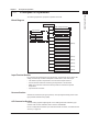
SM 04L41B01-01E CN6 CN7 RS-422 RS-232 CN8 CN15 CN1 CN3 CN4 CN2 POW INP POW INP SCREW INLET CN1 The parentheses ( ) contain the descriptions from chapter 6. (LCD) DX1000: page 6-3, item 3 DX1000N: page 6-12, item 4 CN1 (FFC) CN3 CN5 CN1 CN1 CN4 DX1000: page 6-3, item 8 DX1000N: page 6-12, item 9 LCD & INVERTER UNIT CN2 SW & Sensor BOARD ASSY CN3 (CONN.
5-2 CN2 CN12 CN3 CN13 CN4 CN14 CN1 CN21 CN6 USB CN25 CN1 (AD STD/ISO nn CH) page 6-23, item 41 AD SCANNER BOARD ASSY (S/I-PWR Terminal) page 6-26, items 27, 38 CN1 RS-422 RS-232 POW INP POW INP SCREW INLET CN8 CN2 CN3 CN4 POWER TERM.
Chapter 6 6.1 Customer Maintenance Parts List Customer Maintenance Parts List (DX1000) Customer Maintenance Parts List 1 2 Model DX1002, DX1004, DX1006, DX1012 Daqstation DX1000 3 R 4 C A A AM V 0V 40 10 -2 z N 0 H 10 /60 50 L X 5 6 Customer Maintenance Parts List na e in Chi Mad H STY S . O N 08 26 U R . L O DE N MO TA G TA G IX . FF C O SU LE S R N 17 Y -0122 .
6.1 Customer Maintenance Parts List (DX1000) 2 Complete Set 8 M X A 6 A 0V 10 N / 50 C VA z H 60 L 40 0-2 10 7 9 na e in Chi Mad LY PP SU IX 20 LE S R M U O S DE 08 R C 17 26 L SU FF N CY 4 0 H STY F NO REQU . EN 1 TA G 2 1-2 7-0 200 . NO TA G . NO TA G . NO 14 2 12 11 9 CF 3 CA RD 10 13 Item 1 2 3 4 5 Part No.
6.1 Customer Maintenance Parts List (DX1000) Bezel and Key Case Assembly 3 1 1 2 2b 2c 3 4 5 8 6 9 10 2 5 7 2a 3 11 4 5 7 6 14 Customer Maintenance Parts List 15 7 1 2 2c 5 6 9 10 DIS TEP/ R EN 2b 12 13 Note: *1 not /KB1 /KB2 *2 /KB1 or /KB2 (CMP) Item 1 2 2a 2b 2c Part No.
6.1 Customer Maintenance Parts List (DX1000) 4 Main Assembly (1/2) 33 2 11 15 13 14 12 17 16 17 17 5 4 10 9 3 6 10 10 7 32 8 10 33 34 20 18 19 60VA z 0H 50/6 MAX 37 G TA G TA G TA G TA G TA G TA . NO . NO . NO . NO . NO E YL S ST H . NO 36 22 -01- 2007 DEL MO R IX SUFF US LY Y 8 SUPP UENC C 260 EQ FR 17 O. de in ina Ch Ma N 35 00 N2 21b 21a 28 1 31 31 30 29 27 US B CF CA RD 25 24 23 22 26 Note: (CMP) CMPL 04L41B01-01E 6-4 Nov.
6.1 Customer Maintenance Parts List (DX1000) 3 4 5 6 7 8 9 10 11 12 13 23 24 25 26 27 28 29 30 31 32 33 34 35 36 37 Note : *1 *2 *3 *4 Apr.
6.1 Customer Maintenance Parts List (DX1000) 6 Terminal Assembly (1/3) 22 23 17 24 19 20 18 21 21 23 25 15 16 12 13 8 9 10 14 11 14 16 4 5 6 26 28 27 29 3 2 1 CMPL 04L41B01-01E 6-6 7 Note: (CMP) Apr.
6.
6.
6.1 Customer Maintenance Parts List (DX1000) Standard Accessories 9 1 2 1 2 12 3 4 4 13 3 5 5 14 6 7 Customer Maintenance Parts List 6 7 15 9 10 8 16 11 Item 1 2 3 4 5 Part No. B9991AD B8706ZZ E9655FX B8706FX Qty 1 1 5 2 6 7 8 9 10 11 B9900BX B8706NQ B8702EA A1070EB B8702AE B8702AD 2 1 1 2 1 1 Bracket Assembly (not /H5 /H5 ) CF Card 128 MB (The size and model may change.
6.2 Customer Maintenance Parts List (DX1000N) Customer Maintenance Parts List Model DX1002N, DX1004N DX1006N, DX1012N Daqstation DX1000N C A A AM V 0V 00 24 1 N 0- 0Hz 0 6 1 / 50 L X R na e in Chi Mad . S O N 08 26 U R 1-22 2007 -0 O TA G TA G N O . L . DE O MO C N 17 LE S R N SU FF IX SU PP EQ LY UE NC Y G N FR TA . H STY 20 0 1 2 3 4 5 6 7 8 9 10 11 12 DIS TEP/ R EN Note: Parts marked with a symbol are Customer Maintenance Parts (CMP).
6.2 Customer Maintenance Parts List (DX1000N) 2 1 Complete Set 50 100 L /60H-240 z1 V 0 A N 0VA MC AX 11 12 13 2 e in 14 ina Ch Mad E L S 20 SU 8 U 60 M R 2 17 L IX DE S FF O SU TA G C 22 -01- 2007 NO . TA G . NO TA G . NO 7 N LY R PP 0 T S H CY 6 3 Y 10 F NO REQU . EN 9 16 4 7 1 5 4 5 6 Customer Maintenance Parts List 15 7 14 8 3 Item 1 2 3 4 5 Part No.
6.2 Customer Maintenance Parts List (DX1000N) 3 Bezel and Key Case Assembly 1 12 13 11 7 9 16 15 10 6 8 13 12 2 3b 3c 3 3a 4 5 22 16 6 20 6 21 14 1 2 5 6 17 9 10 DIS 3c TEP/ R EN 3b 18 19 Item 1 2 3 3a 3b 3c Part No. B8705GA B8705FH B8705BD B8705BB B8705FK B8705FL Qty 1 1 1 1 2 2 4 A1078VA B8703KB B8705HC B9988DM B8705RD B8705SD 1 1 1 6 1 1 LCD Back Light Unit DISP Bracket Assembly Screw CONN.W.O.OPT.PBA (not /KB1 /KB2) (select) CONN.REM.OPT.
6.2 Customer Maintenance Parts List (DX1000N) 1 Case and Inside Assembly (1/3) 4 13 1 11 10 22 19 24 23 17 16 14 15 20 21 19 18 2 9 4 2a 3 8 6 5 9 6 7 9 2b 3 10b 10a 4 5 34 28 28 26 32 35 33 6 25 38 41 40 39 37 44 36 43 42 45 31 30 27 29 US B CF CA RD 50 46 47 48 49 Note: (CMP) CMPL 04L43B01-01E SM 04L41B01-01E Nov.
6.2 Customer Maintenance Parts List (DX1000N) 5 Case and Inside Assembly (2/3) 4 5 6 7 8 9 B8705RF B8705RQ B8705DJ A1252EH A1252EH B1007BL B1007BL S9763VK A1258EH Y9305LB Y9305LB DX1012N 3 DX1006N 2b DX1004N 2a Part No.
6.2 Customer Maintenance Parts List (DX1000N) 6 1 Case and Inside Assembly (3/3) Part No.
6.2 Customer Maintenance Parts List (DX1000N) 7 Terminal Assembly (1/3) 17 18 15 16 12 13 8 9 10 14 11 14 16 4 5 6 19 20 1 ( /H2) 3 21 2 23 3 22 2 1 7 Note: (CMP) Jul.
6.2 Customer Maintenance Parts List (DX1000N) 8 1 Terminal Assembly (2/3) 2 3 23 4 5 6 7 Part No. B9968DF B8705FF A1923JT B9968DF B9968DN Qty 1 1 1 1 1-6 1 1 1 1 8 9 10 11 12 13 14 15 16 17 18 E9655FX B8706FE Y9310LB Y9306EB B9900SG Y9405LB Y9401WL 1 1 3 1 1 1 2 1 2 1 1 S-Power Terminal (select) *5 POW TERM SCR.
6.
6.2 Customer Maintenance Parts List (DX1000N) 10 1 Standard Accessories 2 1 3 2 4 4 5 3 5 6 Customer Maintenance Parts List 7 7 6 9 10 8 Item 1 2 3 4 5 Part No. B9991AD B8706ZZ E9655FX B8706FX Qty 1 1 5 2 6 7 8 9 10 11 B9900BX B8706NQ A8702EA A1070EB B8702AE B8702AD 2 1 1 2 1 1 11 Description CD for DAQSTANDARD CD-ROM for Manuals Manuals B.H.Screw (M4x6) Door Lock Key Bracket Assembly CF Card 128 MB (The size and model may change.
6.3 Customer Maintenance Parts List (DX2000) Customer Maintenance Parts List Model DX2004,DX2008,DX2010,DX2020 DX2030,DX2040,DX2048 Daqstation DX2000 M A X R A 0V N 10 z 0-2 10 C VA 40 0H /6 50 L de in ina Ch Ma E S IX R 17 2 8 60 O O. M US DE L SU FF 00 C LY EN PP U SU EQ FR . O N Y H STYL N2 GN R C TA 22 -01- 2007 O. GN TA O.
6.3 Customer Maintenance Parts List (DX2000) 2 1 Complete Set 10 de in 9 ina Ch Ma 0 20 N C LY EN PP U SU EQ FR . O N 2 O C 08 US M 26 R 11 17 DE L SU FF IX R Y T S H Y E L S 50 100L /60H 240V z 10 A N 0VA MC AX 8 O. GN TA O. GN TA 13 O. GN TA 22 -01- 2007 3 4 1 5 4 3 6 y. nl NO. PO 12V 7 6368 21 WE 926 R 2 11 5 7 6 Item 1 2 3 4 5 Part No.
6.3 Customer Maintenance Parts List (DX2000) Bezel and Key Case Assembly Item 1 2 3 Part No. B8706BA B8706BB B9968PA A1048VZ Qty 1 1 1 1 4 B8706BM B8706BY B8706BR 1 1 1 5 Apr.
6.3 Customer Maintenance Parts List (DX2000) 4 1 Main Assembly (1/3) 4 8 12 9 12 13 16 14 16 15 16 2 12 1 5 3 3 2 4 11 6 12 7 12 10 6 Customer Maintenance Parts List 17 25 26 18 24 20 19 22 21 27 23 5 29 28 7 36 30 39 32 32 30 36 37 32 40 35 38 41 33 42 32 35 39 43 32 44 46 31 CMPL 04L42B01-01E SM 04L41B01-01E 34 45 46 35 32 Apr.
6.
6.
6.3 Customer Maintenance Parts List (DX2000) 7 Terminal Assembly (1/4) 36 37 to Rear Panel 53 52 34 35 29 31 32 33 30 33 28 53 35 27 47 26 49 48 51 20 22 21 44 38 43 41 46 45 23 40 42 39 42 44 57 25 24 X A AC A M 0V 0V 24 10 0 Hz 10 /60 50 - 7 9 8 10 12 11 16 15 14 50 19 18 17 ( /H2) 1,4,7,10 2,5,8,11 3,6,9,12 54 3 2 58 1 51 55 54 56 55 6 5 4 Apr.
6.
6.
6.
6.3 Customer Maintenance Parts List (DX2000) 11 Standard Accessories 1 2 12 4 13 3 5 14 7 6 15 9 10 8 Item 1 2 3 4 5 Part No. B9991AD B8706ZZ E9655FX B8706FX Qty 1 1 1 5 2 6 7 8 9 10 11 B9900BX B8706NQ A8702EA A1070EB B8702AE B8702AD 2 1 1 2 1 1 Bracket Assembly (not /H5 /H5 ) CF Card 128 MB (The size and model may change.
Chapter 7 7.1 Replacing Parts Introduction 1 This section describes replacing parts necessary for maintenance and repair. Replaceable Parts 2 When it becomes necessary to replace parts, it is recommended to replace entire assemblies rather than specific parts within assemblies. If you plan on replacing parts yourself, please refer to the Customer Maintenance Parts List (CMPL) in chapter 6 for a list of parts supplied by Yokogawa. Parts not on this list are not available through Yokogawa.
7.2 Recommended Replacement Periods for Worn Parts To preserve the reliability of the DX and to use the DX in a good condition for an extended time, it is recommended that periodic replacements be made on parts. The replacement parts may change to accommodate preventive maintenance over extended time. Be sure to check with your nearest YOKOGAWA dealer. The following table shows the recommended replacement period for expendable parts.
7.3 Notes Pulling Out the Inner Instrument (DX1000N) 1 This section explains how to pull out the inner instrument. Refer to these instructions as well when reinstalling. 3 WARNING • When reinstalling the inner instrument, check that no foreign objects are inside the case, that the connector pins are not bent, and that no other abnormalities exist. These can be causes of fire, electric shock, and damage to instruments. • Always turn OFF the power switch when pulling out the inner instrument.
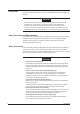
7.3 Pulling Out the Inner Instrument (DX1000N) Testing If the DX hardware style number is 1, perform the tests below (see chapter 3) after reinstalling the inner instrument. The hardware style number is printed on the name plate. The name plate is on the top of the case (outer side). MODEL STYLE H S SUFFIX Hardware style number SUPPLY FREQUENCY NO.
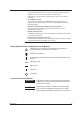
7.3 Pulling Out the Inner Instrument (DX1000N) 1 5. Open the bezel upward, then fix in the upright position with the side stay. 2 3 Stay 6. Turn OFF the power switch. Turn ON when reinstalling the inner instrument. 4 Power switch 5 2 3 4 1 Fastening Torque 6 0.4 N.m 7. Loosen the screw. (Screw tightening torque: 0.4 to 0.5 N·m). 3 4 Replacing Parts 7 Screw 1 Fastening Torque 0.4 N.m 5 CF CARD USB 8.
7.