User’s Manual YTA Series Temperature Transmitters (Hardware) [Style: S3] IM 01C50B01-01E IM 01C50B01-01E 14th Edition
YTA Series Temperature Transmitters (Hardware) IM 01C50B01-01E 14th Edition CONTENTS 1. Preface........................................................................................................ 1-1 ■ Notes on the User’s Manual............................................................................. 1-1 ■ Notes on Safety and Modifications................................................................... 1-1 ■ For Safe Use of Product.............................................................
5. Wiring.......................................................................................................... 5-1 5.1 Notes on Wiring.................................................................................................. 5-1 5.2 Loop Construction............................................................................................. 5-1 5.3 Cable Selection.................................................................................................. 5-1 5.4 6.
1. 1-1 <1. Preface> Preface The YTA temperature transmitter is fully factorytested according to the specifications indicated on the order. In order for the YTA temperature transmitter to be fully functional and to operate in an efficient manner, the manual must be carefully read to become familiar with the functions, operation, and handling of the YTA. This manual gives instructions on handling, wiring and maintenance of YTA110, YTA310 and YTA320 temperature transmitters.
(d) Modification • Yokogawa will not be liable for malfunctions or damage resulting from any modification made to this instrument by the customer. Symbols used in this manual The YTA temperature transmitter and this manual use the following safety related symbols and signals. WARNING Contains precautions to protect against the chance of explosion or electric shock which, if not observed, could lead to death or serious injury.
<1. Preface> 1-3 ■ ATEX Documentation This procedure is only applicable to the countries in European Union.
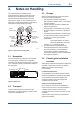
2-1 <2. Notes on Handling> 2. Notes on Handling The YTA temperature transmitter is fully factorytested upon shipment. When the YTA is delivered, check the appearance for damage, and also check that the transmitter mounting parts shown in Figure 2.1 are included with your shipment. If “No Mounting Bracket” is indicated, no transmitter mounting bracket is included.
(3) Impact and Vibration It is recommended that the instrument be installed in a location that is subject to a minimum amount of impact and vibration. 2.5 Use of a Transceiver Although the temperature transmitter is designed to resist influence from high frequency noise; use of a transceiver in the vicinity of installation may cause problems. Installing the transmitter in an area free from high frequency noise (RFI) is recommended. 2.
or more is confirmed (or 20MΩ if the unit is equipped with a built-in arrester). 3. Upon completion of the test, remove the insulation resistance meter, connect a 100KΩ resistor between the transition wiring and the grounding terminal, and allow the electricity to discharge. Do not touch the terminal with your bare hands while the electricity is discharging for more than 1 second. 2.6.2 Withstand voltage test procedure Testing between the output terminal and the input terminal 1.
a) CSA Intrinsically Safe Type/Non-incendive Type Caution for CSA Intrinsically safe type. (Following contents refers “DOC No. ICS008-A13 P.1-1 and P.1- 2”) Note 1. Model YTA110/CU1, YTA310/CU1 and YTA320/CU1 temperature transmitters are applicable for use in hazardous locations: Certificate 172608-0001053837 [For CSA C22.2] • Applicable Standard: C22.2 No.0, C22.2 No.0.4, C22.2 No.25, C22.2 No.94, C22.2 No.142, C22.2 No.157, C22.2 No.
2-5 <2. Notes on Handling> • When installed in Division 2, “FACTORY SEALED, CONDUIT SEAL NOT REQUIRED”. Note 3. Operation • Keep strictly the “WARNING” on the label attached on the transmitter. WARNING: OPEN CIRCUIT BEFORE REMOVING COVER. OUVRIR LE CIRCUIT AVANT D´ENLEVER LE COUVERCLE. • Take care not to generate mechanical spark when access to the instrument and peripheral devices in hazardous location. Note 4.
(1) Technical Data a) ATEX Intrinsically Safe “ia” Caution for ATEX Intrinsically safe “ia” Note 1. Model YTA110/KU2, YTA310/KU2 and YTA320/KU2 temperature transmitters for potentially explosive atmospheres: • No. KEMA 02ATEX1026X • Applicable Standard: EN 60079-0:2009, EN 60079-11:2007, EN 60079-26:2007, EN 60529:1991 • Type of Protection and Marking code: II 1 G Ex ia IIC T4...T5 • Temperature Class: T5, T4 • Ambient Temperature: –40 to 70°C for T4, –40 to 50°C for T5 • Enclosure: IP67 Note 2.
<2. Notes on Handling> • Ambient Temperature for Dust Atmospheres: –40 to 65°C (T70°C), –40 to 80°C (T90°C) • Enclosure: IP67 Note 2. Electrical Data • Supply voltage: 42 V dc max. • Output signal: 4 to 20 mA Note 3. Installation • All wiring shall comply with local installation requirement. • The cable entry devices shall be of a certified flameproof type, suitable for the conditions of use. Note 4. Operation • Keep strictly the “WARNING” on the label on the transmitter.
2-8 <2. Notes on Handling> Hazardous Area Non-hazardous Area Temperature Transmitter Associated Apparatus 1 SUPPLY + 2 SENSOR 3 SUPPLY – 4 5 C + WARNING SENSOR The instrument modification or parts replacement by other than authorized Representative of Yokogawa Electric Corporation is prohibited and will void the certification.
For example, the production year of the product engraved in “NO.” column on the name plate as follows is 2006. C2F616294 The year 2006 *2: “180-8750” is a postal code which represents the following address. 2-9-32 Nakacho, Musashino-shi, Tokyo Japan *3: The identification number of Notified Body 2.7.3 FM Certification a) 2-9 <2. Notes on Handling> FM Intrinsically Safe Type Caution for FM Intrinsically safe type. Note 1.
<2. Notes on Handling> • For the sensor input circuitry, these nonincendive parameters must be taken into account when installed. • Installation Requirements between temperature transmitter and general purpose equipment: Voc ≤ Vmax, Isc ≤ Imax, Ca ≥ Ci + Ccable, La ≥ Li + Lcable Voc , Isc, Ca and La are non-incendive field wiring parameters of general purpose equipment. Note 3. Installation • The general purpose equipment must be FM approved which have non-incendive field wiring parameters.
<2. Notes on Handling> 2.7.4 TIIS Certification 2.7.5 IECEx Certification a) a) TIIS Flameproof Type The model YTA /JF3 temperature transmitter, which has obtained certification according to technical criteria for explosion-protected construction of electric machinery and equipment (Standards Notification No.556 from the Japanese Ministry of Labor) conforming to IEC standards, is designed for hazardous areas where explosive gases and/or inflammable vapors may be present.
<2. Notes on Handling> [Installation Diagram] [Installation Diagram] Hazardous Location Transmitter 1 + 2 Supply 3 – 4 Sensor 5 Nonhazardous Location Safety Barrier *1 Hazardous Location (Zone 2 only) Temperature Transmitter + + Suppry – – Nonhazardous Location Power Supply + – F0212.ai *1: b) 2-12 In any safety barriers used the output current must be limited by a resistor “R” such that Imaxout-Uz/R. IECEx Intrinsic safety “ic” Caution for IECEx Intrinsic safety “ic”. Note 1.
<2. Notes on Handling> 2-13 Note 5. Maintenance and Repair • The instrument modification or parts replacement by other than authorized representative of Yokogawa Electric Corporation is prohibited and will void IECEx Flameproof Certification. 2.
3-1 <3. Part Names and Functions> 3. Part Names and Functions 3.1 Part Names Burn out output direction setting pin upon hardware failure Name plate Stud bolt CPU assembly Terminal cover LCD assembly (with indicator) Grounding terminal Tag plate Grounding terminal Amp. cover Lock screw (for ATEX, IECEx and TIIS flameproof type) Wiring connector (output signal side) Wiring connector (input signal side) Built-in indicator display Output signal terminal Input signal terminal F0301.
3.2 Setting the Hardware Error Burnout Change-over Switch The temperature transmitter is equipped with a hardware error burnout function used to set the output direction upon hardware error, and a sensor burnout function that sets the direction of the output in the event of burnout of the temperature sensor.
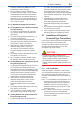
For a list of error codes, refer to “Error code table” in Section 6.4. (6) Unit display The unit specified as the unit of process in the process variable display column in Item (5) is lit. The output display is fixed to mA or %. (7) Display of sensor type and number of wire connections Displays process variable/output items, the number of sensor wiring connections and the multidrop address in dot matrix (only applies to HART communication). In the event of hardware error, “FAIL” is displayed. <3.
<4. Installation> 4. 4-1 Installation IMPORTANT • When performing on-site pipe fitting work that involves welding, use care to prevent outflow of the welding current into the transmitter. • Do not use the transmitter as a foothold for installation. Horizontal Pipe Mounting • For details of choosing the installation location, refer to the guidelines outlined in Section 2.4, “Choosing the installation location”. • The mounting bracket shown in Figure 4.
5. 5-1 <5. Wiring> Wiring 5.1 Notes on Wiring IMPORTANT • Apply a waterproofing sealant to the threads of the connection port. (It is recommended that you use non-hardening sealant made of silicon resin for waterproofing.) • Lay wiring as far away as possible from electrical noise sources such as large transformers, motors and power supplies. • Remove the wiring connection dust-caps before wiring.
When a thermocouple is used as the temperature sensor, a compensation wire must be used that it appropriate for the type of thermocouple (refer to compensating cables for JIS C 1610/IEC584-3 thermocouples). When a resistance temperature sensor (RTD) is used as the temperature sensor, 2-core/3-core/4-core cable must be used (refer to resistance thermometer sensor JIS C 1604/ IEC751). The terminal of the dedicated cable is a 4 mm screw. 5-2 <5.
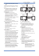
5.4.2 Output Terminal Connection Sensor1(YTA110, YTA310) 1 2 3 4 5 (A) 1 2 3 4 5 (+) (–) Thermocouple and DC voltage (1) Connection of output signal/power supply cable (B) RTD and resistance (2-wire) (A) 1 2 3 4 5 (A) 1 2 3 4 5 (B) (B) RTD and resistance (3-wire) Figure 5.6 Connect the output signal cable (shared with the power supply cable) to the – terminal and the + terminal. For details, refer to Figure 5.2, “Loop construction”.
5.5 <5. Wiring> Wiring Cautions (1) General-use Type and Intrinsically Safe Type Use metal conduit wiring or a waterproof gland (metal wiring conduit JIS F 8801) for cable wiring. • Apply nonhardening sealant to the threads of the wiring tap and a flexible fitting for secure waterproofing. Figure 5.10 shows an example of wiring on the output side. This example also applies to the wiring on the input side.
Lock nut 5-5 <5. Wiring> 5.6 Union coupling Clamp nut Clamp ring Washer Grand Rubber packing Packing box Lock nut Adapter body Cable Union cover O-ring CAUTION Grounding Grounding is always required for the proper operation of transmitters. Follow the domestic electrical requirements as regulated in each country. For a transmitter with built-in lightning protector, grounding should satisfy ground resistance of 10Ω or less.
6. 6-1 <6. Maintenance> Maintenance 6.1 General Each component of this instrument is configured in units to make maintenance easier. This chapter contains disassembly and assembly procedures associated with calibration, adjustment and part replacement required for maintenance of the affected instrument. IMPORTANT 1. Maintenance of this instrument should be performed in a service shop where the necessary tools are provided. 2.
3. For thermocouple input Since this instrument is equipped with a reference junction compensating function, use a reference junction compensating function in universal calibrator in order to compensate for this function upon calibration. According to the reference milivolt table for thermocouple, obtain milivolt corresponding to 0, 25, 50, 75, or 100% of the span, and use that power as the input value, then deliver it from the universal calibrator to the temperature transmitter.
6-3 <6. Maintenance> 6.3.1 Replacement of Built-in Indicator 6.3.2 Replacement of CPU Assembly Removal of built-in indicator Removal of CPU assembly 1. Remove the cover. 2. Loosen two mounting screws while using your hand to support the built-in indicator. 3. Remove the LCD assembly from the CPU assembly. At this time, straighten and pull the LCD assembly forward so that the connector connecting the CPU assembly and the LCD assembly is not damaged. 1. Remove the cover. 2.
6.4 Troubleshooting 6.4.2 Example of Troubleshooting Flow When the measured value is found abnormal, follow the troubleshooting flowchart below. If the complex nature of the trouble means that the cause cannot be identified using the following flowchart, refer the matter to our service personnel. 6.4.
Table 6.3 Problems, Causes and Countermeasures Observed Problems Output fluctuates greatly. Transmitter outputs fixed current. Possible Cause Span is too narrow. Related Parameter (BRAIN protocol) (HART protocol) F10:LRV F20:URV PV LRV (4) PV URV (5) Input adjustment by user was not corrctly done. J05:SNSR1 CLR K05:SNSR2 CLR Output adjustment by user was not correctly done. The transmitter is in manual (test output) mode. Input adjustment by user was not corrctly done.
6.5 6-6 <6. Maintenance> Integral Indicator and Error Display For temperature transmitters equipped with an integral indicator, errors in the temperature sensor or the transmitter cause an integral indicator to call up the applicable error code. Table 6.4 lists the error codes and the associated corrective actions. Table 6.4 List of Error Codes Indicator N/A Er-01 BT200 display Good Output Too Low Cause Output operation upon error Action Input value is lower than the PV low range value.
7-1 <7. General Specifications> 7. 7.1 General Specifications Standard Specifications For the specifications of Fieldbus communication type marked with (◊), refer to IM 01C50T02-01E.
<7. General Specifications> 7-2 Effect of supply voltage fluctuation: ±0.005%/V Insulation: Input/output insulated at 500 V DC Mounting: Mounted on 2B pipes and wall Degrees of Protection: IP66/IP67, NEMA 4X Electrical connection: Refer to “Model and Specification Codes”. Case and cover: Aluminum alloy casting Painting: Polyurethane resin baked finish Deep sea moss green (equivalent of Munsell 0.6GY3.1/2.
7-3 <7. General Specifications> Table 7.
7-4 <7. General Specifications> Table 7.
7-5 <7. General Specifications> Factory setting (◊) Tag No. Left blank if not specified in order Unit of calibration range Input sensor type Lower calibration range Upper calibration range “Pt100, 3-wire” if not specified in order “0” if not specified in order “100” if not specified in order Damping constant 2 seconds Sensor burnout High side (110%, 21.6 mA DC) *1 Output when transmitter fails High side (110%, 21.6 mA DC) *2 *1: *2: 7.
<7. General Specifications> 7-6 [For Explosion Protected Types] For FOUNDATION Fieldbus explosion protected type, see IM 01C50T02-01E.
7-7 <7. General Specifications> 7.4 Dimensions Unit: mm (Approx. inch) ● 2-inch horizontal pipe mounting 65.4(2.57) 111(4.37) 47(1.85) 66(2.60) Electrical Connection (Input signal) Electrical Connection (Output signal) 18.5 (0.73) Terminal Cover With Indicator (Optional) 102 (4.02) ø93 (3.66) 164 (6.46) Shrouding Bolt (For Explosionproof type) Ground Terminal 40 (1.57) 25 (0.98) Tag Plate Horizontal Pipe Mounting Bracket (Optional) 2-inch pipe, ø60.5(ø2.38) 56(2.21) 70(2.76) 90(3.
Installation and Operating Precautions for TIIS Flameproof Equipment Apparatus Certified Under Technical Criteria (IEC-compatible Standards) 1. General (4) Path length of joint surface The following describes precautions on electrical apparatus of flameproof construction (hereinafter referred to as flameproof apparatus) in explosion-protected apparatus.
• • • • Specific cables shall be used as recommended by the “USER’S GUIDELINES for Electrical Installations for Explosive Gas Atmospheres in General Industry,” published in 1994. In necessary, appropriate protective pipes (conduit or flexible pipes), ducts or trays shall be used for preventing the cable run (outside the cable glands) from damage.
Customer Maintenance Parts List YTA Series Temperature Transmitter [ Style : S3 ] 7 12 8 2 1 13 20 2 11 5 3 9 10 18 3 4 6 2 1 17 29 16 28 14 15 For FOUNDATION Fieldbus Type 27 12 30 31 24 25 21 15 26 19 23 22 6 YTA_CMPL.ai All Rights Reserved.
Item Part No.
Revision Information Title : Model YTA series Temperature Transmitter (Hardware) [Style: S3] Manual No. : IM 01C50B01-01E Edition Date Page 1st Sep. 1998 — 2nd Nov. 1998 2-5 2-7 2-9 5-5 7-2 to 7-3 3rd Jan. 1999 2-9 5-3 6-2 6-7 6-9 7-1 7-5 7-6 CMPL 4th June 1999 Contents 2-1 2-7 2-10 2-12 2-13 5-1 5-3 5-6 6-3 7-4 EX-B02E Revised Item New Publication 2.7.1 2.7.2 2.8 5.5 7.1 Add subsection 2.7.1 CSA certification. Add subsection 2.7.2 CENELEC(KEMA) certificated. Add subsection 2.
ii Edition Date Page 9th April 2003 2-1 4-1 7-5 7-7 CMPL 10th Dec. 2004 — Contents 1-2 1-3 2-6 3-1 6-2 7-5 CMPL 11th Sep. 2006 Cover Contents 2-3, 2-4 2-5, 2-6 2-8, 2-9 2-10 2-11 6-6 7-1 7-3 7-5 7-6, 7-7 Revised Item 7.2 7.4 CMPL Add Vertical pipe mounting bracket. Add Vertical pipe mounting bracket. Add mounting bracket code D. Change Dimensions. 01C50B01-02E 8th to 9th Add Part No. Item Part No. 27 F9284NZ 28 F9165QB 29 F9616NU 30 Y9600SU 31 Y9601BU Change Title of Flameproof (JIS → TIIS) 1.