
Datasheet


YZ-WS5N40N
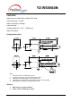
Soldering Conditions - Lamp Type LED
Solder the LED no closer than 3mm from the base of the epoxy bulb. Soldering beyond the base of the tie
bar is recommended
Recommended soldering conditions
Dip Soldering
Pre-Heat
Pre-Heat Time
Solder Bath Temperature
Dipping Time
Dipping Position
100 Max.℃
60 sec. Max.
260 Max.℃
5 sec. Max.
No lower than 3mm from the base of the epoxy bulb.
Hand Soldering
3Ø Series Others (Including Lead-Free Solder)
Temperature
Soldering time
Position
300 Max.℃
3 sec. Max.
No closer than 3mm from
the base of the epoxy bulb.
350 Max.℃
3 sec. Max.
No closer than 3mm from
the base of the epoxy bulb.
Do not apply any stress to the lead, particularly when heated
The LEDs must not be repositioned after soldering
After soldering the LEDs, the epoxy bulb should be protected from mechanical shock or vibration until the
LEDs return to room temperature.
Direct soldering onto a PC board should be avoided. Mechanical stress to the resin may be caused by the
PC board warping or from the clinching and cutting of the leadframes. When it is absolutely necessary, the
LEDs may be mounted in this fashion, but, the User will assume responsibility for any problems. Direct
soldering should only be done after testing has confirmed that no damage, such as wire bond failure or
resin deterioration, will occur. YOLDAL’s LEDs should not be soldered directly to double sided PC boards
because the heat will deteriorate the epoxy resin.
When it is necessary to clamp the LEDs to prevent soldering failure, it is important to minimize the
mechanical stress on the LEDs.
Cut the LED leadframes at room temperature. Cutting the leadframes at high temperatures may cause
LED failure.
Copyright © 2004 All Rights Reserved. YOLDAL email: info@yoldal.com 2012 / 02 Page ― 3 ―