
Installation manual


66901 / 035-20393-001 Rev. C (1204)
Unitary Products Group 3
GROUND INSTALLATION
The unit may be installed at ground level on a solid base that will not
shift or settle, causing strain on the refrigerant lines and possible leaks.
Maintain the clearances shown in Figure 1 and install the unit in a level
position.
Normal operating sound levels may be objectionable if the unit is placed
directly under windows of certain rooms (bedrooms, study, etc.).
Isolate the unit from rain gutters to avoid any possible wash out of the
foundation.
ROOF INSTALLATION
When installing units on a roof, the structure must be capable of sup-
porting the total weight of the unit, including a pad, lintels, rails, etc.,
which should be used to minimize the transmission of sound or vibra-
tion into the conditioned space.
UNIT PLACEMENT
1. Provide a base in the pre-determined location.
2. Remove the shipping carton and inspect for possible damage.
3. Compressor tie-down bolts should remain tightened.
4. Position the unit on the base provided.
LIQUID LINE FILTER-DRIER
The air conditioning unit’s copper spun bi-flow filter/dryer is located on
the liquid line.
NOTE: Replacements for the liquid line drier must be exactly the same
as marked on the original factory drier. See Source 1 for O.E.M.
replacement driers.
PIPING CONNECTIONS
The outdoor condensing unit must be connected to the indoor evapora-
tor coil using field supplied refrigerant grade copper tubing that is inter-
nally clean and dry. Units should be installed only with the tubing sizes
for approved system combinations as specified in tabular data sheet.
The charge given is applicable for total tubing lengths up to 15 feet. See
Application Data Part Number 036-61920-000 for installing tubing of
longer lengths and elevation differences.
NOTE: Using a larger than specified line size could result in oil return
problems. Using too small a line will result in loss of capacity
and other problems caused by insufficient refrigerant flow. Slope
horizontal vapor lines at least 1" every 20 feet toward the out-
door unit to facilitate proper oil return.
PRECAUTIONS DURING LINE INSTALLATION
1. Install the lines with as few bends as possible. Care must be taken
not to damage the couplings or kink the tubing. Use clean hard
drawn copper tubing where no appreciable amount of bending
around obstruction is necessary. If soft copper must be used, care
must be taken to avoid sharp bends which may cause a restriction.
2. The lines should be installed so that they will not obstruct service
access to the coil, air handling system, or filter.
3. Care must also be taken to isolate the refrigerant lines to minimize
noise transmission from the equipment to the structure.
4. The vapor line must be insulated with a minimum of 1/2" foam rub-
ber insulation (Armaflex or equivalent). Liquid lines that will be
exposed to direct sunlight and/or high temperatures must also be
insulated.
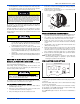
Tape and suspend the refrigerant lines as shown. DO NOT allow tube
metal-to-metal contact. See Figure 2.
5. Use PVC piping as a conduit for all underground installations as
shown in Figure 3. Buried lines should be kept as short as possible
to minimize the build up of liquid refrigerant in the vapor line during
long periods of shutdown
6. Pack fiberglass insulation and a sealing material such as perma-
gum around refrigerant lines where they penetrate a wall to reduce
vibration and to retain some flexibility.
7. See application part number 036-61920-000 for additional piping
information.
PRECAUTIONS DURING BRAZING OF LINES
All outdoor unit and evaporator coil connections are copper-to-copper
and should be brazed with a phosphorous-copper alloy material such
as Silfos-5 or equivalent. DO NOT use soft solder. The outdoor units
have reusable service valves on both the liquid and vapor connections.
The total system refrigerant charge is retained within the outdoor unit
during shipping and installation. The reusable service valves are pro-
vided to evacuate and charge per this instruction.
Serious service problems can be avoided by taking adequate precau-
tions to ensure an internally clean and dry system.
Failure to do so or using a substitute drier or a granular type may
result in damage to the equipment.
Filter-Drier
Source 1 Part No.
Apply with Models
CZE / AC5B / AL5B
029-22195-000 All
This system uses R-410A refrigerant which operates at higher pres-
sures than R-22. No other refrigerant may be used in this system.
Gauge sets, hoses, refrigerant containers, and recovery systems
must be designed to handle R-410A. If you are unsure, consult the
equipment manufacturer.
Never install a suction-line filter drier in the liquid line of an R-410A
system. Failure to follow this warning can cause a fire, injury or
death.
FIGURE 2: Tubing Hanger
FIGURE 3: Underground Installation
Liquid
Line
Incorrect
Correct
Tape
Sheet Metal Hanger
Insulated Vapor Line
TO INDOOR COIL
TO OUTDOOR UNIT
LIQUI D LINE
CAP
PVC
CONDUIT
INSULATED
VAPOR LINE