036-21335-002-A-1102 ® TECHNICAL GUIDE PROVEN PERFORMANCE SPLIT-SYSTEM AIR-COOLED GENERAL EVAPORATOR BLOWER 25, 30, 40 & 50 TON LA300, LB360, 480 & 600 The LA/LB line is a flexible performer. LA300, LB360 & 480 can be positioned in up to 12 different positions and suspended in various positions. The LB600 can be positioned in up to 7 different arrangements and suspended also.
036-21335-002-A-1102 TABLE OF CONTENTS LIST OF TABLES DESCRIPTION . . . . . . . . . . . . . . . . . . . . . . . . . . . . . 4 MODULAR DESIGN . . . . . . . . . . . . . . . . . . . . . . . . . 4 FACTORY-MOUNTED COMPONENTS . . . . . . . . . . 4 ACCESSORIES . . . . . . . . . . . . . . . . . . . . . . . . . . . . . 4 GUIDE SPECIFICATIONS . . . . . . . . . . . . . . . . . . . 23 LIST OF FIGURES Fig. 1 2 3 4 5 6 7 8 9 10 11 12 13 14 15 16 17 18 2 Pg. PRODUCT NOMENCLATURE . . . . . . . . . . . . . . . . .
036-21335-002-A-1102 YORK SPLIT INDOOR PRODUCT NOMENCLATURE L A 300 C 00 A 6 A AA 1 A Model Number Description Options L Product Category L = Air Handling Unit - Cooling F = Air Handling Unit - Heat Pump A Product Identifier A = R-22 Standard Efficiency 2-Pipe B = R-22 Standard Efficiency 4-Pipe 300 Nominal Cooling Capacity MBH 300 = 25 Ton 360 = 30 Ton 480 = 40 Ton 600 = 50 Ton C Heat Type C = Cooling Only 00 Nominal Heating Capacity 00 = No Heat Installed A Airflow Options A = None 6
036-21335-002-A-1102 DESCRIPTION Evaporator blower units are designed with two distinct modules to provide maximum application flexibility. The 25, 30 and 40 ton units are shipped as single packages with the blower module mounted on top of the coil module, The blower module can be repositioned in the field to meet almost any installation requirement. Blower and coil modules for the 50 ton units are shipped separately to simplify handling.
036-21335-002-A-1102 STEAM COILS (LA300 & LB360 only): A steam coil is available on the 25 & 30 Ton for installation between the blower and coil modules of both horizontal and vertical units. Since the casing matches the dimensions and the finish of the basic unit, it becomes an integral part of the unit after installation. The coil slides out of the casings for easy installation and is pitched in the casings to facilitate condensate drainage.
036-21335-002-A-1102 NOTE: The following illustration shows how the channels should be secured to the unit using the hardware provided with the suspension accessory.
036-21335-002-A-1102 TABLE 3: CORNER WEIGHTS Unit Weight UNITMODEL Shipping Operation LA300 1180 1125 LB360 1180 1146 LB480 1510 1426 LB600 1572 1640 Configuration HORIZONTAL VERTICAL HORIZONTAL VERTICAL HORIZONTAL VERTICAL HORIZONTAL VERTICAL A 276 262 281 266 348 292 451 484 B 317 301 323 307 414 348 386 414 C 285 301 290 307 361 427 370 342 D 247 262 252 266 303 359 433 400 TABLE 4: ACCESSORY OPERATING WEIGHT DISTRIBUTION (LBS)1 ACCESSORY LA300 LB360 LB480 LB600 BASE2 25 25
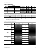
036-21335-002-A-1102 TABLE 6: UNIT DRIVE DATA ADJUSTABLE MOTOR PULLEY UNIT MODEL LA300 LB360 LB480 LB600 FIXED BLOWER PULLEY DRIVE KIT MODEL NUMBER BLOWER RPM RANGE PITCH DIA. (IN.) BORE (IN.) PITCH DIA. (IN.) BORE (IN.) 1LD0440 600 - 750 4.0 - 5.0 1 1/8 12.0 1LD0407 700 - 850 4.2 - 5.2 1 3/8 1LD0442 780 - 940 5.3 - 6.3 1LD0415 636 - 795 1LD0407 BELTS QTY. PITCH LENGTH (IN.) DESIGNATION 1 3/16 2 63.3 A62 11.0 1 3/16 2 63.3 A62 1 3/8 12.0 1 3/16 2 63.3 A62 4.
036-21335-002-A-1102 TABLE 8: HOT WATER COIL CAPACITIES1 UNIT MODEL HOT WATER COIL MODEL ENTERING WATER TEMPERATURE MINUS ENTRY AIR TEMPERATURE °F.
036-21335-002-A-1102 TABLE 10: STEAM COIL CAPACITIES1, MBH @ 2 PSIG2 UNIT MODEL STEAM COIL MODEL DRY BULB TEMPERATURE OF AIR ENTERING COIL (°F) CFM 10 30 50 70 6,000 471 424 380 330 8,000 535 483 432 380 10,000 592 535 478 422 12,000 642 580 518 456 8,000 535 483 432 380 10,000 592 535 478 422 12,000 642 580 518 456 14,000 687 621 555 489 LA300 1NF0454 LB360 1. These capacities do not include any blower motor heat. 2.
036-21335-002-A-1102 7/8 KNOCKOUTS FOR POWER AND CONTROL WIRING AIR OUT M AIR OUT K 5/8 5/8 L K J D E { LESS BOTTOM PANEL C BLOWER SECTION AIR IN D AIR IN EVAPORATOR SECTION EVAPORATOR COIL SECTION 5/8 PANEL A See detailed drawings for piping and drain connections on following pages.
036-21335-002-A-1102 LIQUID SYS. #1 LIQUID LIQUID SYS. #2 SUCTION SYS. #1 SYS.
036-21335-002-A-1102 FIGURE 11: UNIT DIMENSIONS - LB600 4.7" 13.5" Liquid Line Sys. #1 4.0" 10.1" Liquid Line Sys. #2 3.8" 24.0" Suction Line Sys. #2 3.0" 23.86" 2.1" Condensate Drain 6.0" 13.5" Suction Line Sys. #1 3.0" 6.
036-21335-002-A-1102 FIGURE 13: HOT WATER COIL DIMENSIONS TABLE 14: HOT WATER COIL DIMENSIONS COIL MODEL UNIT MODEL DIMENSIONS A B C D E F 1HW0406 LA300 LB360 100-1/8 37-7/8 6-3/4 3-7/8 1-3/8 1-3/8 1HW0407 LB480 LB600 103-1/8 45-1/4 6-1/2 4 1-5/8 1-5/8 FIGURE 14: STEAM COIL DIMENSIONS TABLE 15: STEAM COIL DIMENSIONS1 COIL MODEL UNIT MODEL 1NF0454 LA300 LB360 1.
036-21335-002-A-1102 TABLE 17: PHYSICAL DATA MODEL DESCRIPTION LA300 LB360 LB480 LB600 4 x 40 4 x 40 4 x 50 4 x 62 93 93 96 96 Face Area, Feet2 25.8 25.8 33.3 41.
036-21335-002-A-1102 TABLE 17: PHYSICAL DATA MODEL DESCRIPTION COMPONENT WEIGHT LA300 LB360 LB480 LB600 Basic Unit (Less Motor & Drive) 980 980 1260 1474 Shipping Weight (lbs) 1180 1180 1510 1572 Operating Weight (lbs) 1125 1146 1426 1640 Hot Water Coil 150 150 190 190 Steam Coil 160 160 - - 117 (5hp) 117 (5hp) - - 120 (7.5hp) 120 (7.5hp) 120 (7.
036-21335-002-A-1102 TABLE 18: ELECTRICAL DATA UNIT MODEL HP FLA VOLTAGE (3PH-60HZ) MIN. CIRCUIT AMPACITY MAX. FUSE SIZE (Amps) 16.7 208 21 35 15.2 230 19 30 7.6 460 10 15 6.1 575 8 15 24.2 208 30 50 22 230 28 45 11 460 14 20 9 575 11 20 16.7 208 21 35 15.2 230 19 30 7.6 460 10 15 6.1 575 8 15 24.2 208 30 50 22 230 28 45 11 460 14 20 9 575 11 20 30.8 208 39 60 28 230 35 60 14 460 18 30 11 575 14 20 24.
036-21335-002-A-1102 TABLE 19: FAN PERFORMANCE DATA - 25 TON1 CFM 8,000 RPM 9,000 10,000 11,000 12,000 SP2 BHP3 KW SP2 BHP3 KW SP2 BHP3 KW SP2 BHP3 KW SP2 BHP3 KW 600 - - - 0.30 2.5 2.3 0.20 3.1 2.9 0.02 3.6 3.4 - - - 635 0.56 2.4 2.3 0.43 2.7 2.6 0.31 3.3 3.1 0.13 3.8 3.5 - - - 700 0.80 3.0 2.8 0.68 3.3 3.1 0.54 3.7 3.5 0.38 4.2 3.9 0.20 4.8 4.5 775 1.12 3.7 3.4 1.00 4.0 3.7 0.85 4.4 4.1 0.70 4.8 4.5 0.54 5.3 5.0 800 1.
036-21335-002-A-1102 LA300 & LB360 3.2 10 00 3.0 RP M 2.8 10 90 0R PM 2.4 8 P BH 2.2 2.0 80 0R PM 700 1.4 P BH P BH 1.2 4 RPM P BH P BH 1.6 6 5 1.8 3 600 RPM 1.0 2 P BH TOTAL STATIC PRESSURE, IWG P BH 2.6 0.8 500 RPM 0.6 0.4 0.2 0 0 10 20 30 40 50 60 70 80 90 100 110 120 130 140 150 160 170 180 190 200 210 220 230 CFM (X 100) Available external static pressure for unit accessories and the duct system.
036-21335-002-A-1102 TABLE 21: FAN PERFORMANCE DATA - 40 TON1 CFM 12,800 RPM 14,400 16,000 17,600 19,200 SP2 BHP KW SP2 BHP KW SP2 BHP KW SP2 BHP KW SP2 BHP KW 600 0.20 4.3 3.7 - - - - - - - - - - - - 640 0.38 4.8 4.1 0.19 5.6 4.8 - - - - - - - - - 700 0.65 5.5 4.7 0.47 6.4 5.5 0.28 7.2 6.2 - - - - - - 775 0.99 6.5 5.6 0.84 7.4 6.4 0.66 8.4 7.2 0.46 9.4 8.1 0.23 10.4 9.0 800 1.11 6.8 5.9 0.96 7.8 6.7 0.79 8.8 7.
036-21335-002-A-1102 LB480 3.2 15 P 100 BH 3.0 0R 2.8 PM 12 HP 2B - 1/ 2.6 900 8 RPM P 10 BH 2.2 BH P 2.0 1.8 PM 6 800 R 5 BH P 1.6 P BH TOTAL STATIC PRESSURE, IWG 2.4 1.4 700 RPM 1.2 600 RPM 1.0 0.8 500 RPM 0.6 0.4 0.2 0 0 10 20 30 40 50 60 70 80 90 100 110 120 130 140 150 160 170 180 190 200 CFM (X 100) Available external static pressure for unit accessories and the duct system. Internal unit resistance based on a dry coil plus 2" throwaway filters.
036-21335-002-A-1102 LB600 3.2 90 0 RP M 3.0 2.8 2.6 80 0R PM P BH 2.0 700 RPM 10 1.8 BH P HP 1.6 1.4 HP 16 B P BH 14 12 2.2 8B 600 RPM 1.2 HP 6B TOTAL STATIC PRESSURE, IWG 2.4 PM 1.0 500 R 0.8 0.6 0.4 0.2 0 0 20 40 60 80 100 120 140 160 180 200 220 240 260 280 300 320 340 360 CFM (X 100) AvaIlable external static pressure for unit accessories and the duct system. Internal unit resistance based on a dry coil plus 1" throwaway filters.
036-21335-002-A-1102 GUIDE SPECIFICATIONS EACH UNIT SHALL BE: • • Covered by a 1-year limited parts warranty on the complete unit. THE DIMENSIONS OF EACH UNIT SHALL NOT EXCEED THOSE SPECIFIED.
Subject to change without notice. Printed in U.S.A. Copyright © by Unitary Products Group 2002. All rights reserved.