718434-YTG-A-0811 ® TECHNICAL GUIDE R-410A AFFINITY™ SERIES DEX MODELS 2 - 4 TON 60 Hertz Description These York® Affinity™ packaged air conditioners are designed for outdoor installation. Only utility and duct connections are required at the point of installation. Field-installed electric heater accessories are available to provide electric heat, if required.
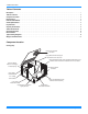
718434-YTG-A-0811 Table of Contents Description . . . . . . . . . . . . . . . . . . . . . . . . . . . . . . . . . . . . . . . . . . . . . . . . . . . . . . . . . . . . . . . . . . . . . . . . . . . . . . . . . . . . . . . . . . . . 1 Table of Contents . . . . . . . . . . . . . . . . . . . . . . . . . . . . . . . . . . . . . . . . . . . . . . . . . . . . . . . . . . . . . . . . . . . . . . . . . . . . . . . . . . . . . . . 2 Component Location . . . . . . . . . . . . . . . . . . . . . . . . . . . . . . . .
718434-YTG-A-0811 Nomenclature Cooling Only D 1 EX 024 A 06 Product Category Voltage Code D = Single Package Air Conditioner (Air Cooled) 06 = 208/230-1-60 25 = 208/230-3-60 46 = 460-3-60 Product Generation 1 = New or Current Design Factory Installed Electric Heat A = No Electric Heat Installed Product Identifier EX = R-410A 15 SEER Nominal Cooling Capacity (MBH) 024 = 24,000 BTUH 030 = 30,000 BTUH 036 = 36,000 BTUH Features and Benefits Standard Features • Operating Efficiency - All air condi
718434-YTG-A-0811 • • • • • • • • • • • 4 rippled fins of the condenser coil muffle the normal fan motor and compressor operating sounds. The unique formed base pan also aids in sound alterations with it's Super-Structure design. This design strategically places embossments in the pan for optimum strength and rigidity. Fan System - All models operate over a wide range of design conditions with an electrically commutated fan motor.
718434-YTG-A-0811 Guide Specifications General Units shall be manufactured by Johnson Controls Unitary Products in an ISO 9001 certified facility. YORK’s Affinity™ package units give you the flexibility and choices you need in today’s market. These packaged air conditioners are designed for outdoor installation. Only utility and duct connections are required at the point of installation.
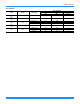
718434-YTG-A-0811 Physical Data DEX024-048 Physical Data Component DEX030 2.5 Models DEX036 3.0 DEX042 DEX048 Nominal Tonnage 3.5 4.0 ARI COOLING PERFORMANCE Gross Capacity @ ARI A point (Btu) 23.5 29.2 36.8 44.5 50.8 ARI net capacity (Btu) 23.2 28.6 36.0 43.5 49.0 EER 12.3 12.3 12.3 12.3 12.3 SEER 15 15 15 15 15 Nominal CFM 800 1000 1150 1400 1600 System power (KW) 1.9 2.3 2.9 3.5 4.
18434-YTG-A-0811 Unit Limitations Model Unit Voltage Unit Limitations Applied Voltage Min Max DEX 208/230-1-60 187 252 115 DEX 208/230-1-60 187 252 115 036 (3.0) DEX 208/230-1-60 208/230-3-60 460-3-60 187 187 432 252 252 504 115 115 115 042 (3.5) DEX 208/230-1-60 187 252 115 048 (4.0) DEX 208/230-1-60 208/230-3-60 460-3-60 187 187 432 252 252 504 115 115 115 Size (Tons) 024 (2.0) 030 (2.
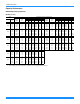
718434-YTG-A-0811 Capacity Performance DEX024-048 Cooling Capacities DEX024 (2.0 Ton) Air on Evaporator Coil CFM 600 800 600 800 600 800 WB (°F) Net Capacity1 (MBh) Total Input (kW)2 90 77 72 67 62 57 77 72 67 62 57 21.5 21.3 21.2 20.2 19.4 30.1 28.4 26.7 24.0 24.4 1.1 1.1 1.1 1.1 1.1 1.6 1.6 1.5 1.5 1.5 7.5 14.3 21.2 20.2 19.4 13.1 19.9 26.7 24.0 24.4 77 72 67 62 57 77 72 67 62 57 21.8 20.0 18.3 16.6 17.0 27.8 25.5 23.2 21.4 21.6 1.4 1.4 1.4 1.4 1.4 2.0 1.9 1.9 1.9 1.8 12.1 15.2 18.3 16.
718434-YTG-A-0811 DEX030 (2.5 Ton) Air on Evaporator Coil CFM 675 1000 675 1000 675 1000 WB (°F) Net Capacity1 (MBh) Total Input (kW)2 90 77 72 67 62 57 77 72 67 62 57 29.5 27.2 25.0 22.8 20.1 37.4 36.3 35.3 31.0 30.5 1.3 1.3 1.3 1.4 1.4 2.1 2.1 2.1 1.9 1.9 14.1 18.6 23.0 22.8 20.1 16.7 24.7 32.7 31.0 30.5 77 72 67 62 57 77 72 67 62 57 26.3 24.2 22.0 20.2 19.9 37.1 32.9 28.6 27.5 27.3 1.7 1.7 1.7 1.7 1.7 2.7 2.5 2.3 2.4 2.4 12.6 17.3 21.9 20.2 19.9 18.1 23.4 28.6 27.5 27.
718434-YTG-A-0811 DEX036 (3.0 Ton) Air on Evaporator Coil CFM 800 1150 800 1150 800 1150 WB (°F) Net Capacity1 (MBh) Total Input (kW)2 90 77 72 67 62 57 77 72 67 62 57 36.6 31.9 27.2 26.6 23.8 48.0 44.5 41.1 37.5 37.6 1.5 1.5 1.5 1.5 1.5 2.4 2.4 2.4 2.3 2.3 17.4 21.9 26.5 26.6 23.8 23.1 30.7 38.3 37.5 37.6 77 72 67 62 57 77 72 67 62 57 31.4 28.4 25.4 23.5 23.5 44.2 40.1 36.0 33.9 33.7 1.9 1.9 1.9 1.9 1.9 3.2 3.1 2.9 2.9 2.9 16.9 21.2 25.4 23.5 23.5 21.3 28.6 36.0 33.9 33.
718434-YTG-A-0811 DEX042 (3.5 Ton) Air on Evaporator Coil CFM 925 1400 925 1400 925 1400 WB (°F) Net Capacity1 (MBh) Total Input (kW)2 90 77 72 67 62 57 77 72 67 62 57 40.2 37.1 34.0 30.5 29.4 61.7 55.5 49.4 44.5 46.0 1.9 1.9 1.9 1.9 1.8 3.4 3.1 3.1 3.0 2.9 21.0 26.3 31.6 30.5 29.4 29.1 37.9 46.7 44.5 46.0 77 72 67 62 57 77 72 67 62 57 34.4 31.8 29.2 25.7 25.6 51.7 47.6 43.5 39.2 39.8 2.4 2.3 2.3 2.4 2.4 3.8 3.7 3.5 3.5 3.5 17.5 23.3 29.1 25.7 25.6 25.3 34.3 43.3 39.2 39.
718434-YTG-A-0811 DEX048 (4.0 Ton) Air on Evaporator Coil CFM 1050 1600 1050 1600 1050 1600 WB (°F) Net Capacity1 (MBh) Total Input (kW)2 90 77 72 67 62 57 77 72 67 62 57 47.3 43.7 40.1 35.9 35.5 66.0 61.0 56.0 51.7 50.8 2.2 2.1 2.1 2.1 2.1 3.6 3.5 3.4 3.3 3.2 23.6 30.5 37.3 35.9 35.5 30.9 42.4 53.9 51.7 50.8 77 72 67 62 57 77 72 67 62 57 42.1 38.5 35.0 31.8 31.3 58.1 53.6 49.0 45.6 44.9 2.7 2.7 2.7 2.7 2.7 4.2 4.1 4.0 3.9 3.9 21.6 28.3 35.0 31.8 31.3 29.0 39.0 49.0 45.6 44.
718434-YTG-A-0811 Airflow Performance Side Duct Application DEX024-048 Size (Tons) Model Mode Low Cool 024 (2.0) DEX High Heat Low Cool 030 (2.5) DEX High Heat Low Cool 036 (3.0) DEX High Heat Low Cool 042 (3.5) DEX High Heat Low Cool 048 (4.
718434-YTG-A-0811 Bottom Duct Application DEX024-048 Size (Tons) Model Mode Low Cool 024 (2.0) DEX High Heat Low Cool 030 (2.5) DEX High Heat Low Cool 036 (3.0) DEX High Heat Low Cool 042 (3.5) DEX High Heat Low Cool 048 (4.
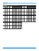
718434-YTG-A-0811 Additional Static Resistance Size (Tons) Model 024 (2.0) DEX 030 (2.5) DEX 036 (3.0) DEX 042 (3.5) DEX 048 (4.0) DEX CFM Wet Indoor Coil Economizer1 Filter/Frame Kit Electric Heat 500 600 700 800 900 1000 1100 1200 700 800 900 1000 1100 1200 1300 700 800 900 1000 1100 1200 1300 1400 1100 1200 1300 1400 1500 1600 1100 1200 1300 1400 1500 1600 1700 1800 1900 2000 0.01 0.01 0.01 0.01 0.01 0.02 0.03 0.04 0.01 0.01 0.01 0.02 0.03 0.04 0.07 0.01 0.01 0.01 0.02 0.03 0.04 0.
718434-YTG-A-0811 Electric Heat Minimum Supply Air Size (Tons) Model 024 (2.0) 030 (2.5) Voltage DEX 208/230-1-60 5.0 7.5 630 630 Minimum Supply Air (CFM) Heater kW 10.0 15.0 800 20.0 25.0 - - - DEX 208/230-1-60 630 630 800 800 - - 036 (3.0) DEX 208/230-1-60 208/230-3-60 460-3-60 1070 1070 1070 1070 1070 1070 1070 1070 1070 1070 1070 1070 - - 042 (3.5) DEX 208/230-1-60 1225 1225 1225 1225 - - 048 (4.
718434-YTG-A-0811 Electrical Data DEX024-048 Cooling Only With/Without Electric Heat Size (Tons) Volt MCC OD Fan Motors (each) FLA Supply Blower Motor FLA Compressors (each) RLA LRA 024 (2.0) 208/230-1-60 10.2 52 16 1.2 4.3 030 (2.5) 208/230-1-60 14.1 70 22 1.2 4.3 208/230-1-60 16.6 82 26 1.2 4.3 208/230-3-60 11.1 58 17 1.2 4.3 4.5 29 7 0.8 4.3 208/230-1-60 16.6 96 26 1.4 6.8 208/230-1-60 21.1 96 33 1.7 6.8 208/230-3-60 13.4 88 21 1.7 6.8 41 10 1.0 6.
718434-YTG-A-0811 Typical Wiring Diagrams Typical DEX024, 048 Cooling Only 208/230-1-60 volt Wiring Diagram 18 Johnson Controls Unitary Products
718434-YTG-A-0811 Typical DEX036, 048 Cooling Only 208/230-3-60 volt Wiring Diagram Johnson Controls Unitary Products 19
718434-YTG-A-0811 Typical DEX036, 048 Cooling Only 460-3-60 volt Wiring Diagram 20 Johnson Controls Unitary Products
718434-YTG-A-0811 Weights and Dimensions Unit 4 Point Load Weight "D" CENTER OF GRAVITY FRONT OF UNIT "C" "A" 49-1/8 "B" X Weight (lbs.) Center of Gravity Size Model (Tons) Shipping Operating X Y 024 DEX 360 355 22.25 25 (2.0) 030 DEX 395 390 22.25 25 (2.5) 036 DEX 405 400 22.25 25 (3.0) 042 DEX 415 410 22.25 25 (3.5) 048 DEX 445 440 22.25 25 (4.0) 47-1/4 Y 4 Point Load Location (lbs.
718434-YTG-A-0811 Cooling Only Unit Dimensions HIGH VOLTAGE CONN. 7/8" DIA. KNOCKOUT FRONT COMPRESSOR SERVICE ACCESS COMPARTMENT PANEL HIGH VOLTAGE CONN. 1-31/32" DIA. KNOCKOUT LOW VOLTAGE CONN. 7/8" DIA. KNOCKOUT “A” 2-3/8 (OVERALL) SIDE SUPPLY AIR OPENING REFRIGERANT CONNECTIONS SIDE RETURN AIR OPENING ELECTRICAL/FILTER SERVICE ACCESS COMPARTMENT PANEL 17-1/4 28-1/4 22-1/4 49-1/8 (OVERALL) HIGH VOLTAGE CONN. 1-23/64" DIA.
718434-YTG-A-0811 Unit Dimensions Front and Bottom HIGH VOLTAGE CONN. 1-3/32" DIA. KNOCKOUT 8-7/8 11-7/8 19-1/4 FRONT GAS SUPPLY 1-5/8" DIA. KNOCKOUT (1/2" NPTF CONNECTION) LOW VOLTAGE CONN. 7/8" DIA. KNOCKOUT LOW VOLTAGE CONN. 7/8" DIA. KNOCKOUT HIGH VOLTAGE CONN.
718434-YTG-A-0811 Unit Typical Duct Applications ROOF CURB INSTALLATION REAR DUCT ROOF CURB INSTALLATION BOTTOM DUCT SLAB ON GROUND INSTALLATION Unit Typical Slab on Ground Installation SUPPLY AIR DUCT RETURN AIR DUCT FIELD SUPPLIED DISCONNECT SWITCH LOCATED TO REAR OF UNIT TO POWER SUPPLY CONTROL WIRING TO INDOOR THERMOSTAT 24 Johnson Controls Unitary Products
718434-YTG-A-0811 Unit Typical Roof Curb Installation FIELD SUPPLIED DISCONNECT SWITCH MOUNTED ON UNIT TO POWER SUPPLY CONTROL WIRING TO INDOOR THERMOSTAT SUPPLY AIR DUCT RETURN AIR DUCT Unit Accessory Dimensions Roof Curb1 RECOMMENDED DUCT SIZE 17-1/2" x 16-3/4" 42-2/3 40-3/4 3-1/2 45-1/8 17-5/8 17-1/4 43-1/4 OPENING FOR RETURN AIR DUCT 22 OPENING FOR SUPPLY AIR DUCT 14 1 RECOMMENDED DUCT SIZE 17-1/8" x 21-1/2" 1. 8” Roof Curb also available.
Roof Curb Cross Section \ 1" 3/4" x 1" WIDE GASKETING FOR CURB FRAME AND ALL DUCT SUPPORT SURFACES UNIT BASE UNIT BASE RAIL WOOD NAILER COUNTERFLASHING 8" MIN. ABOVE FINISHED ROOF 14" CANT STRIP CURB FRAME INSULATION AND ROOFING MATERIAL INSULATION ROOF DECK AND ROOFING MATERIAL Subject to change without notice. Printed in U.S.A. Copyright © 2011 by Johnson Controls, Inc. All rights reserved.