
International Oil and Gas Conversion Burner Installation Manual


107272-UIM-B-1105
16 Unitary Products Group
Alternate
NOTE: Roof flashing, PVC pipe, PVC 90° elbows and fire stop are not
supplied with the furnace.
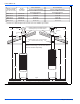
LOCATING AND CUTTING ROOF JACK OPENING
To facilitate the proper installation of the roof jack, it is very important
that the roof jack opening in the ceiling and roof be on the same vertical
center line as the furnace flue collar. See Figures 30 and 31.
Mark this location on ceiling and scribe a circle with a 5" (1.5 m) radius
{10" (25.4 cm) diameter} around this mark. Cut opening for roof jack
through ceiling and roof. (If furnace was installed during construction,
cover furnace and flue opening to prevent debris from entering flue
when hole is cut for roof jack).
INSTALLING ROOF JACK IN ROOF
1. Pr
ovide protection for Vent Connector and Air-Intake Connector
from damage and debris.
2. Mark Roof Jack center line on ceiling. Cut a 5" (1.5 m) radius {10"
(25.4 cm) diameter} hole through ceiling.
3. Mark Roof Jack center line on roof. Cut oblong hole through roof.
4. Insert Roof Jack through roof opening. Do not secure Roof Jack to
roof.
Connect Roof Jack to Furnace
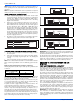
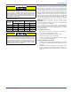
1. Install Flue Shield inside Vent Connector. Push Flue Shield down
until in contact with the built-in stop inside the Vent Connector. See
Figures 28 and 29.
2. Verify gasket is around outside of Air-Intake Connector. Install new
gasket if missing or damaged.
3. Pull the Roof Jack's telescoping section down onto furnace. Fully
engage Roof Jack onto Vent Connector and Air-Intake Connector
and compress gasket. See Figure 29. Refer to Interior Roof Jack
Extension installation instructions, if applicable.
4. Align holes in Roof Jack and Air-Intake Connector. Secure Roof
Jack to furnace using #10 x 1/2 - 1-1/2" (#10 x 1.3 - 3.8 cm) Type
AB or Type B sheet metal screw.
INTERIOR EXTENSIONS
There is an optional 11” (43.2 cm) long interior extension that can be
used to provide added interior roof jack length, if needed. To choose the
proper length roof jack with or with-out the optional extension see Fig-
ures 30 and 31 and Table 9. More than one interior extension may be
used to accommodate “A” dimensions up to 110” (284.5 cm).
NOTE: Use of an interior extension will increase the roof jack adjust-
able heights by the amount of the interior extension height.
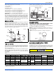
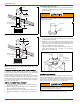
FIGURE 26: Combustion Air Inlet Pipe
FIGURE 27: Combustion Air Inlet Pipe Alternate
Rubber Coupling
with Hose Clamp
2” Pipe
9” Min.
12” Min.
6” Min.
6” Min. or 6” Above
the Snow Line
Rubber Coupling
with Hose Clamp
2” Pipe
9” Min.
12” Min.
6” Min. or 6” Above
the Snow Line
6” Min.
Failure to install the Flue Shield may cause premature flue pipe
deterioration. Damaged flue pipe can result in asphyxiation, fire or
equipment malfunction.
FIGURE 28: Flue Shield Installation
FIGURE 29: Roof Jack Attachment to Furnace
The joint where the optional interior extension connects to the roof
jack must be below the ceiling. Failure to observe this requirement
may result in asphyxiation, fire, or explosion
Flue Shield
Furnace
Vent
Connector
Bottom of
Roof Jack
Vent
Connector
Gasket
Front of
Furnace
Roof Jack
Air Intake
Connector
Opening for
Combustion Air
Inlet Grommet