
International Oil and Gas Conversion Burner Installation Manual


107272-UIM-B-1105
20 Unitary Products Group
VENT SYSTEM
This furnace is a sealed combustion (direct vent) unit and is design cer-
tified to use only a 4000 Series roof jack. These roof jacks are designed
to exhaust flue products to the outside.
INSTALLING CEILING RING
The ceiling ring is to meet fire stop requirements. Accessory Ceiling
Ring may be installed in Manufactured (mobile) Homes or Modular
Homes.
Refer to the UL 311 Standard for Safety for Roof Jacks for Manufac-
tured Homes and Recreational Vehicles; or in Canada use CAN/CSA-
Z240 MH Series (latest edition) or applicable provisions of the state,
regional or local building codes and these instructions. The installer
must follow approved methods in the above standards and/or codes for
a fire stop. If required, the installer may use up to three sections of the
Accessory Ring. Refer to Figure 33.
NOTE: A portion of the outer edge of the ceiling ring may be trimmed so
the ring will fit between the warm air plenum and roof jack.
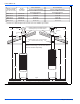
VENT CLEARANCES
IMPORTANT: The vent must be installed with the minimum clearances
as shown in Figure 34, and must comply with local, state, regional
codes and requirements.
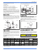
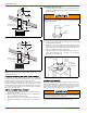
FIGURE 32: Installing Roof Jack Extension
Upper
Cap
Lower
Cap
Crown
Assembly
Base
STEP 1:
Remove upper and lower cap.
Remove the two (2) screws
that secure the upper cap to
the crown assembly base and
remove the upper cap. Next,
remove the three (3) screws
that secure the lower cap to
the crown assembly base.
Set bothcaps aside for later use.
EXTENSION
CROWN
ASSEMBLY
BASE
STEP 2: .
Place the roof jack extension on top of the
crown assembly base, pushing down firmly
to assure a snug fit.
IMPORTANT: Make sure that the pipes are
connected.
Using the four (4) holes at the base of the
extension as a guide, drill four (4) holes
1/8” diameter into the crown assembly base.
Secure the extension to the crown assembly
base with the four (4) screws provided.
Install the lower cap on top of the extension
so that the center pipe sticks through
the hole in the lower cap.
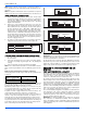
UPPER
CAP
LOWER
CAP
EXTENSION
BRACKET
EXTENSION
CROWN
ASSEMBLY
BASE
STEP 3:
Reinstall upper and lower cap to extension.
Using the three (3) screws removed
in Step 1, attach the lower cap to the
extension bracket. Install the upper
cap over the center pipe of the extension.
Using the two (2) holes located at the
base of the upper cap as guides, drill
two (2) 1/8” diameter holes into the center pipe.
Finally, attach the upper cap to the center
pipe using the two (2) screws removed in
Step 1 to the center pipe.
STEP 4:
Complete assembly.
Place these instructions in the customer
packet provided with the furnace.
FIGURE 33: Ceiling Ring