SEALED COMBUSTION DOWNFLOW GAS FURNACE MODELS: DGAA, For Installation DGAH, DGPA, AND DGPH In: 1, Manufactured (Mobile) Homes 2. RecreationaIVehicles 3. Modular Homes & Buildings & Park Models IMPORTANT - Only individuals having proven expedence with this type of equipment shouldattempt to performset-up. Proper furnace set-up and adjustment is the responsibility of the retailer/homeowner and is not covered under warranty.
035-16328-002 Rev.
035-16328-002 Rev. C (0902) GENERAL INFORMATION NOTE: The words which is essential mance. "Shall" or "Must" indicate a requirement to satisfactory and safe product perfor- The words "Should" or "May" indicate a recommendation or advice which is not essential and not required but which may be useful or helpful. IMPORTANT - These instructions are primarily intended to assist qualified individuals experienced in the proper installation of heating and/or air conditioning appliances.
035-16328-002 Rev.C(0902) RETURN AIR REQUIREMENTS 6. Non-combustiblepans having one-inch upturned flanges are located beneath openings in the floor return duct system. Additional Requirements 7. Additional requirements for floor and ceiling return system for closet installed sealed combustion heating appliance are given in the next paragraph. Wiring materials located in the return duct system conform to Article 300-22 (B&C) of the National Electrical Code (NFPA-70). 8.
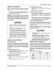
035-16328-002 Rev.C(0902) Furnace to Closet Door Clearance -5 Inches or more Return Air Grille Part No. 7900-287P/A * White The closet door MUST have a minimum o1250 Square Inches of free area in the upper half of the door. If opening for return air is located in the floor or sidewalls and below the top of the furnace casing: 250 SQ. IN MINIMUM FREE AREA 1. 6 inches minimum clearance must be provided on side where return is located, and 2.
035-16328-002 Rev. C (0902) ROOF JACK NEW HOME INSTALLATION If this furnace is installedon a new home do the following: AWARNING 1. Inspect the furnace top collars for signs of insulation or ceiling debris which might have fallen in during cutting of the ceiling and roof holes. Remove all debris before continuing. 2. After unpacking the roof jack, check the rain caps. Insure they are not damaged, tilted or crooked. Do not twist, crush or sit on the roof caps during installation.
035-16328-002 Rev.
035-16328-002 Rev.
035-16328-002 DUCT Rev. C (0902) CONNECTORS I .. - = I , , T.
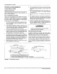
035-16328-002 Rev. C (0902) LOCATOR BRACKET NAILS, FLAT HEAD SCREWS OR STAPLES _ BEND TABS UNDER OPENING TO SECURE TO THE SUPPLY DUCT NAI L_,AFLEATHEAD SC R EWS FLOOR SUPPLY DUCT FIGURE tl : Duct Connector Screw Attachment INSTALLATION OF SCREW A'B'ACHMENT DUCT CONNECTOR SUPPLY DUCT FIGURE t2 : Duct Connector Tab Attachment INSTALLATION OF TAB ATTACHMENT DUCT CONNECTORS 1, Make floor cut out as shown in Figure 9. 1. Make floor cut out as shown in Figure 9. 2.
035-16328-002 Ray.C(0902) LA, CAUTION] The inner flue pipe must be present. FURNACE SEATED AGAINST THE LOCATOR BRACKET \ It is mandatory that the combustion air pipe and flue pipe assembly be fully engaged. The combustion air pipe MUST be securely fastened to the furnace with a sheet metal screw in the hole provided. SECUREFURNACE TO FLOOR WITH TWO NAILS OR SCREWS.
035-16328-092 Rev. C (0902) CEILING RINGS CONNECT THERMOSTAT WIRES The coiling ring is to meet fire stop requirements. Accessory Ceiling Ring (PIN 7660-2841) may be used, (See Figure 15) or the manufactured home manufacturer or the installer may use other approved methods to stop fire. 1. Insert 24 voltwires throughthe small plastic bushing just above the control panel. 2. Connect the thermostat wires to the furnace low voltage pigtails.
035-16328-002 Rev. C (0902) WALL THERMOSTAT Avoid locations where the thermostat could be subject to drafts from outside, or exposed to direct light from lamps, sun, fireplaces, etc., or affected by air from a duct register blowing directly on the thermostat. FURNACE CONTROL BOX The wall thermostat should be located 52 to 66 inches above the floor.
035-16328-002 WIRING Rev. C (0902) DIAGRAMS If" MOTOR B!OWER °11 GND. SCREW 02 03 LN -c 4 05 06 BLK ORG 07 ____ __Z 4 8 TRANSFORMER FAN SWITCH 24V SEC. 120V PRI. WHT MANUAL RESET LIMIT SWITCH I INE ORG (_ GRY _c_ o w 3 AMP FUSE AUTO RESET ORG E NEU. ..... LI W ., WHT LIMIT SWITCH SYSTEM SWITCH GAS CONTROL . " BLK R WALL "lit.... L THERMOSTAT _. GND. TO EARTH GND.
035-16328-002 Rev. C (0902) COMBUSTION BLOWER RELAY 1 O o2 o3 GND. SCREW ORG -o 4 o5 TRANSFORMER o6 WHT LOAD o7 FAN SWITCH 24V SEC. _8 WHT MANUAL RESET LIMIT SWITCI 120V PRI. BLU BRN [_ WHT WHT i :{_]_ RED AUTO RESET LIMITSWITCH 3 AMP FUSE ORG I, W' SYSTEM SWITCH i NEU, WHT _/ LI WALL THERMOSTAT qt PRESSURE SWITCH _ o 1 BLK iv. TO EARTH GND. @ GNO.
035-16328-002 Rev. C (0902) ! I ORG BLOWER ORG l € K 4 I s :_g BLOWER RELAY ORG GRY 6 MOTOR I_ 7 BLK MANUAL RESET t I I TRANSFORMER 9 i BLEND-AIR CONTROL BOX [ (IF EQUIPPED { ] , . - I >- 24V SEC. WHT i I FAN SWITCH © LOAD LIMIT SWITCH i , ..._ s°c%w LINE BRN i i BLU i GRN , i WHT WHT RED AUTO RESET LIMIT SWITCH 3 AMP FUSE [_]i b • • , i' BLK r 1 AIC i CONDENSING I UNIT J CONTACTORI L ...... J LUl 2°_w_ WALL THERMOSTAT E {_i .,vAc "lit NEU.
035-16328-002 Rev. C (0902) BLOWER MOTOR ORG '1 _2 BLEND AIR CONTROL BOX (IF EQUIPPED) ! I I I WHT MANUAL RESET LIMIT SWITCH ORG / ORG COMBUSTION BLOWER RELAY _, GRY _5 A/C )6 BLOWER RELAY m :). EW FAN SWITCH 81 2N zl.oo TRANSFORMEEp 120V 24V LOAD SE(pR I m_ Z / _}_ IT © GRN i_ WriT i_ WHT RED RED AUTO RESET LIMIT SWITCH 3 AMP FUSE ' I_ BLK , F -I AJC l I CONDENSING I I UNIT I CONTACTOR I W, -J' O _ NEU. G°°°:]w R ,,,VAt WA,, THERMOSTAT "lit L PRESSURE _,._ L ......
035-16328-002 Rev.C(0902) UPPER I LIMIT SWITCH BLU CRY ORG LIMIT OWER SWITCH Q YEL i © RED WALL THERMOSTAT TO A]C CONDENSING UNIT (if equipped) BLK __,J BLK ............ X ERL_ BLOW MOTOR m O o o BLK BLK WHT RED RED I WHT WHT TRANSFORMER VAC i GROUND ....SCRI _A D-_ SYSTEM SWITCH NEUTRAL 115 VAC O_w ;i3mc 7 I Or-o WHT o Z ca L o; I TO EARTH GROUND WHT 5 o I I COMBUSTION AIR SWITCH BRN BRN c---..-- I GAS I VALVE _----.-- L1 INCOMING POWER MUST BE POLARIZED.
035-16328-002 Rev. C (0902) GAS PIPING INSTALLATION AND CHECKING OF GAS LINE Gas Supply piping must be sized in accordance with the recommendations contained in National Fuel Gas Code (ANSIZ223.1, NFPA-54) unless local codes or regulations state otherwise. Matedals used and pipe sizing for U.S. manufactured homes must comply with requirements contained in Manufactured Homes Al19.1, Recreational Vehicles Al19.2 and H.U.D. Title 24, Section 3280.705 and any local or state codes.
035-16328-002 Rev.C(0902) FINAL PROCEDURE FURNACE AND AIR CONDITIONER INSTALLATIONS INSTALL FURNACE DOORS Install the lower door first by sliding the bottom of the door down until the tabs on the casing base engage the slots in the bottom door end cap. Then push the top of the lower door in until the door clips snap into place. Install the upper door in a similar manner, first engaging the slots in the top of the upper door on the tabs on the casing top.
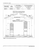
035-16328-002 Rev. C (0902) HIGH ALTITUDE DERATION CHART NATURAL GAS 56,000--lnput Odfice Drill Pa_ # Dia. Size 70,000--Input Odfce Dnll Pa_ # Dia. Size 0.136 0.136 29 29 9951-1361 9981--1361 0,154 0.149 23 25 9951--1541 9951--1491 0.128 0.128 30 30 9981--1281 9951--1281 0.128 0.128 30 30 9951-1281 9951-1281 0,149 0,147 0,144 25 26 27 9951--1491 9951-1471 9951-1441 0.144 27 9951-1441 7,000 0.129 31 9951--1291 8,000 9,000 0.120 0.120 31 31 9951-1201 9951_-1201 0.140 0.
035-16328-002 Rev.
035-16328-002 Rev.
035-16328-002 Rev. C (0902) DGAH ITEM 2 4 DESCRIPTION DGAH056BBSA DGAH077BBSA Switch, Pressure 024-27666-000 024-27666-600 Tubing Silicone (2' Req'd) 028-11957-000 028-11957-000 Limit Switch,Manual (Upper) 025-35358-000 025-35358-009 Assembly, Booster (w/Motor) 373-19801-820 373-19601420 Control Board, Integrated 031-01932-006 031-61932-069 6 Valve, Gas 7 Bracket, Valve 8 Thermostat (Heat/Cool) 7990-328P 7999-328P 073-19891-064 073-19801-064 AP.
035-16328-002 Rev.C(0902) DGPA ITEM 2 DESCRIPTION DGPA077ABTA DGPA090ABTA ....... 024-27666-000 Tubing Silicone (2' Req'd) ........ 028-11957-000 Assembly, Booster (w/Motor) Control Board, Integrated 6 Valve, Gas 7 Bracket, Valve 8 Thermostat (Heat/Cool) 9 Exchanger, Heat (w/Gaskets) 10 Sensor, Flame 025-35358-000 025-35358-000 025-35358_000 ........ 025-35358-000 373-19601-820 ..........
035-16328-002 Rev.
035-16328-002 Rev. C (0902) BURNER 056 MODEL NATURAL GAS LP GAS 4, ORIFICE 9951-1361 9951-0821 CHART (Normal Altitude Only 4) 070 077 9951-1541 9951-0931 9951-1611 9951-0981 090 9951-1801 9951-1061 NOTES Contact Customer Service for installations at altitudes over 2000 feet above sea level. =<=Across from row indicates a change in that row.
NOTES Subject to change without notice. Printed in U.S.A. Copyright © by York Intemational Corp. 2002. All rights reserved. Unitary Products Group 035-16328-002 Rev. C (0902) Supersedes: 0035-16328-002 Rev. B (1001) P.O.