INSTALLATION MANUAL SUNLINE MagnaDRY™ GAS/ELECTRIC SINGLE PACKAGE AIR CONDITIONERS CONTENTS GENERAL . . . . . . . . . . . . . . . . . . . . . . . . . . . . . . . . . . . .4 MODELS: DR180, 240 & 300 SAFETY CONSIDERATIONS . . . . . . . . . . . . . . . . . . . . .4 INSPECTION . . . . . . . . . . . . . . . . . . . . . . . . . . . . . . . . . .4 REFERENCE . . . . . . . . . . . . . . . . . . . . . . . . . . . . . . . . . .4 RENEWAL PARTS . . . . . . . . . . . . . . . . . . . . . . . . . . . . .5 APPROVALS . .
035-19084-001-D-0504 TABLE OF CONTENTS CONTENTS . . . . . . . . . . . . . . . . . . . . . . . . . . . . . . . . . . . 1 SAFETY CONSIDERATIONS . . . . . . . . . . . . . . . . . . . . . 4 INSPECTION . . . . . . . . . . . . . . . . . . . . . . . . . . . . . . . . . . 4 REFERENCE. . . . . . . . . . . . . . . . . . . . . . . . . . . . . . . . . . 4 RENEWAL PARTS . . . . . . . . . . . . . . . . . . . . . . . . . . . . . 5 APPROVALS . . . . . . . . . . . . . . . . . . . . . . . . . . . . . . . . .
035-19084-001-D-0504 LIST OF FIGURES Fig. # LIST OF TABLES Pg. # Tbl. # Pg. # 1 TYPICAL RIGGING . . . . . . . . . . . . . . . . . . . . . . . . . . . 18 1 UNIT APPLICATION DATA. . . . . . . . . . . . . . . . . . . . . 17 2 CENTER OF GRAVITY . . . . . . . . . . . . . . . . . . . . . . . . 18 2 CONTROL WIRE SIZES . . . . . . . . . . . . . . . . . . . . . . . 22 3 FIXED OUTDOOR AIR DAMPER . . . . . . . . . . . . . . . . 19 3 ELECTRIC HEAT APPLICATION DATA. . . . . . . . . . .
035-19084-001-D-0504 GENERAL YORK Model DR units are either single package cooling units equipped with optional factory installed electric heaters, or single package gas-fired central heating furnaces with cooling unit. Both are designed for outdoor installation on a rooftop or slab. FIRE OR EXPLOSION HAZARD Failure to follow safety warnings exactly could result in serious injury, death, or property damage. The units are completely assembled on rigid, permanently attached base rails.
035-19084-001-D-0504 • 035-19854-000 - Economizer Damper Accessory • 035-08032-002 - Propane Conversion Accessory (USA) • 035-13073-001 - High Altitude Accessory (Natural Gas) • 035-08524-002 - High Altitude Accessory (Propane) This product must be installed in strict compliance with the enclosed installation instructions and any applicable local, state, and national codes including, but not limited to, building, electrical, and mechanical codes.
Heat Type & Nominal Heat Capacity C00 = Cooling Only. No field installed electric heat Gas Heat Options N24 = 240 MBH Output Aluminized Steel N32 = 320 MBH Output Aluminized Steel, (15-25T Only) S24 = 240 MBH Output Stainless Steel S32 = 320 MBH Output Stainless Steel, (15-25T Only) Electric Heat Options E18 = 18 KW E36 = 36 KW E54 = 54 KW E72 = 72 KW Nominal Cooling Capacity - MBH 180 = 15 Ton 240 = 20 Ton 300 = 25 Ton Product Identifier R = R-22 Reheat Unit Product Category D = Air Cond.
035-19084-001-D-0504 PRODUCT NOMENCLATURE - CONTINUED 15-25T Sunline Magna DRY™ Model Number Nomenclature Additional Options - Standard Cabinet AA AB AC AD AE AF AG AH AJ AK AL AM AN AP AQ AR AT AU AV AW AX AY AZ CA CB CC CD CE CF CG CH CJ CK CL CM CN CP CQ CR CS CT CU CV CW CX CY CZ C1 C2 C3 C4 None Phase Monitor Coil Guard Dirty Filter Switch Phase Monitor & Coil Guard Phase Monitor & Dirty Filter Switch Coil Guard & Dirty Filter Switch Phase Monitor, Coil Guard, & Dirty Filter Switch SS Drain Pan SS Dr
035-19084-001-D-0504 Additional Options - Standard Cabinet C5 C6 C7 C8 C9 JA JB JC JD JE JF JG JH JJ JK JL JM JN JP JQ JR JS JT JU JV JW JX JY JZ J1 J2 J3 J4 J5 J6 J7 J8 J9 HA HB HC HD HE HF HG HH HJ HK HL HM HN HP HQ HR HS HT 8 CPC Controller, DFS, APS, Double Wall, SS Drain Pan, Phase Monitor, & Coil Guard CPC Controller, DFS, APS, Double Wall, SS Drain Pan, & Technicoat Cond Coils CPC Controller, DFS, APS, Double Wall, SS Drain Pan, & Technicoat Evap Coil CPC Controller, DFS, APS, Double Wall, SS Drai
035-19084-001-D-0504 Additional Options - Standard Cabinet HU HV HW HX HY HZ H1 H2 H3 H4 H5 H6 H7 H8 H9 NA NB NC ND NE NF NG NH NJ NK NL NM NN NP NQ NR NS NT NU NV NW NX NY NZ N1 N2 N3 N4 N5 N6 N7 N8 N9 TA TB TC TD TE TF TG TH Honeywell Excel 10 Controller, DFS, APS, SS Drain Pan, & Technicoat Cond Coils Honeywell Excel 10 Controller, DFS, APS, SS Drain Pan, & Technicoat Evap Coil Honeywell Excel 10 Controller, DFS, APS, SS Drain Pan, & Technicoat Evap and Cond Coils Honeywell Excel 10 Controller, DFS, AP
035-19084-001-D-0504 Additional Options - Standard Cabinet TJ TK TL TM TN TP TQ TR TS TT TU TV TW TX TY TZ T1 T2 T3 T4 T5 T6 T7 T8 T9 LA LB LC LD LE LF LG LH LJ LK LL LM LN LP LQ LR LS LT LU LV LW LX LY LZ L1 L2 L3 L4 L5 L6 10 Technicoat Evaporator Coil Technicoat Evaporator Coil & Phase Monitor Technicoat Evaporator Coil & Coil Guard Technicoat Evaporator Coil & Dirty Filter Switch Technicoat Evaporator Coil, Phase Monitor, & Coil Guard Technicoat Evaporator Coil, Phase Monitor, & Dirty Filter Switch Te
035-19084-001-D-0504 Additional Options - Standard Cabinet L7 L8 L9 WA WB WC WD WE WF WG WH WJ WK WL WM WN WP WQ WR WS WT WU WV WW WX WY WZ W1 W2 W3 W4 W5 W6 W7 W8 W9 Simplicity Intelli-Comfort Controller, Double Wall, SS Drain Pan, & Technicoat Evap Coil Simplicity Intelli-Comfort Controller, Double Wall, SS Drain Pan, & Technicoat Evap and Cond Coils Simplicity Intelli-Comfort Controller, Double Wall, SS Drain Pan, Phase Monitor, Coil Guard, & Technicoat Evap and Cond Coils Intelli-Comfort w/Mod Link Co
035-19084-001-D-0504 Additional Options - Hinged Filter Door & Toolless Access Cabinet BT BU BV BW BX BY BZ DA DB DC DD DE DF DG DH DJ DK DL DM DN DP DQ DR DS DT DU DV DW DX DY DZ D1 D2 D3 D4 D5 D6 D7 D8 D9 EA EB EC ED EE EF EG EH EJ EK EL EM 12 Double Wall & Coil Guard Double Wall & Phase Monitor, Dirty Filter Switch & Coil Guard Double Wall & SS Drain Pan Double Wall & SS Drain Pan & Phase Monitor Double Wall & SS Drain Pan & Coil Guard Double Wall & SS Drain Pan & Dirty Filter Switch Double Wall & SS
035-19084-001-D-0504 Additional Options - Hinged Filter Door & Toolless Access Cabinet EN EP EQ ER ES ET EU EV EW EX EY EZ E1 E2 E3 E4 E5 E6 E7 E8 E9 GA GB GC GD GE GF GG GH GJ GK GL GM GN GP GQ GR GS GT GU GV GW GX GY GZ G1 G2 G3 G4 G5 Johnson UNT Controller, DFS, APS & Technicoat Evap. & Cond Coils, Hinged Filter Door & Toolless Access Panels Johnson UNT Controller, DFS, APS, Technicoat Evap.
035-19084-001-D-0504 Additional Options - Hinged Filter Door & Toolless Access Cabinet G6 G7 G8 G9 PA PB PC PD PE PF PG PH PJ PK PL PM PN PP PQ PR Honeywell Excel 10 Controller, DFS, APS, Double Wall, SS Drain Pan, & Technicoat Cond Coils Honeywell Excel 10 Controller, DFS, APS, Double Wall, SS Drain Pan, & Technicoat Evap Coil Honeywell Excel 10 Controller, DFS, APS, Double Wall, SS Drain Pan, & Technicoat Evap and Cond Coils Honeywell Excel 10 Controller, DFS, APS, Double Wall, SS Drain Pan, Phase Monit
035-19084-001-D-0504 Additional Options - Hinged Filter Door & Toolless Access Cabinet UT UU UV UW UX UY UZ U1 U2 U3 U4 U5 U6 U7 U8 U9 QA QB QC QD QE QF QG QH QJ QK QL QM QN QP QQ QR QS QT QU QV QW QX QY QZ Q1 Q2 Q3 Q4 Q5 Q6 Q7 Q8 Q9 Technicoat Evaporator & Condenser Coils & Phase Monitor, Hinged Filter Door & Toolless Access Panels Technicoat Evaporator & Condenser Coils & Coil Guard, Hinged Filter Door & Toolless Access Panels Technicoat Evaporator & Condenser Coils & Dirty Filter Switch, Hinged Filter
035-19084-001-D-0504 Additional Options - Hinged Filter Door & Toolless Access Cabinet XA XB XC XD XE XF XG XH XJ XK XL XM XN XP XQ XR XS XT XU XV XW XX XY XZ X1 X2 X3 X4 X5 X6 X7 X8 X9 16 Intelli-Comfort w/Mod Link Controller, Hinged Filter Door & Toolless Access Panels Intelli-Comfort w/Mod Link Controller, & Phase Monitor, Hinged Filter Door & Toolless Access Panels Intelli-Comfort w/Mod Link Controller, & Coil Guard, Hinged Filter Door & Toolless Access Panels Intelli-Comfort w/Mod Link Controller, P
035-19084-001-D-0504 INSTALLATION INSTALLATION SAFETY INFORMATION: Read these instructions before continuing this appliance installation. This is an outdoor combination heating and cooling unit. The installer must assure that these instructions are made available to the consumer and with instructions to retain them for future reference. 1. Refer to the furnace rating plate for the approved type of gas for this furnace. • Local gas utility requirements. In Canada: • Current Canadian Electrical Code C22.
035-19084-001-D-0504 6. Maintain level tolerance to 1/2 inch maximum across the entire length or width of the unit. Excessive exposure of this furnace to contaminated combustion air may result in equipment damage or personal injury. Typical contaminates include: permanent wave solutions, chlorinated waxes and cleaners, chlorine based swimming pool chemicals, water softening chemicals, carbon tetrachloride, Halogen type refrigerants, cleaning solvents (e.g.
035-19084-001-D-0504 DUCTWORK Ductwork should be designed and sized according to the methods in Manual Q of the Air Conditioning Contractors of America (ACCA). A closed return duct system shall be used. This shall not preclude use of economizers or outdoor fresh air intake. The supply and return air duct connections at the unit should be made with flexible joints to minimize noise. The supply and return air duct systems should be designed for the CFM and static requirements of the job.
035-19084-001-D-0504 COMPRESSORS Units are shipped with compressor mountings factoryadjusted and ready for operation. Do not loosen compressor mounting bolts. FILTERS FIGURE 3 - FIXED OUTDOOR AIR DAMPER CONDENSATE DRAIN Two-inch filters are supplied with each unit, but units can be converted easily to four-inch filters. Filters must always be installed ahead of the evaporator coil and must be kept clean or replaced with same size and type.
035-19084-001-D-0504 THERMOSTAT TERMINALS 1 ( RCB ) REHEAT CONTROL BOARD RC RH R Y1 Y1 Y2 Y2 W1 W1 W2 W2 G G C C X1 OCC X3 TERMINAL BLOCK RH 2 X4 A1 HUM 1 A2 HUM 2 T DEHUMIDISTAT 3 3 T 4 TO REMOTE SENSOR 2ET04701324 IF USED 1 Electronic programmable Thermostat 2ET0770010024 ( includes subbase). 2 Terminals A1 and A2 provide a relay output to close the outdoor economizer dampers when the thermostat switches to the set-back position. 3 Dehumidistat closes on rise in humidity.
035-19084-001-D-0504 THERMOSTAT The room thermostat should be located on an inside wall approximately 56 inches above the floor where it will not be subject to drafts, sun exposure or heat from electrical fixtures or appliances. Follow the manufacturer’s instructions enclosed with the thermostat for general installation procedure. A minimum of seven color-coded insulated wires (#18 AWG) should be used to connect the thermostat to the unit.
035-19084-001-D-0504 TABLE 4: GAS HEAT APPLICATION DATA 0 To 2,000 Feet Above Sea Level 2,000 To 4,500 Feet Above Sea Level Output Capacity (Mbh) 0 To 2,000 Feet Above Sea Level 2,000 To 4,500 Feet Above Sea Level Available on Models Natural Gas Rate (Ft./Hr.) Temp. Rise ºF At Full Input Max. Min. Max. Min. Max. Max. Min. Max.
035-19084-001-D-0504 Natural gas may contain some propane. Propane, being an excellent solvent, will quickly dissolve white lead or most standard commercial compounds. Therefore, a special pipe compound must be applied when wrought iron or steel pipe is used. Shellac base compounds such as Gaskolac or Stalastic, and compounds such as Rectorseal #5, Clyde’s or John Crane may be used. 7.
035-19084-001-D-0504 1. The vaporization rate depends on (a) the temperature of the liquid and (b) the "wetted surface" area of the container or containers. hood to the panel. The top flange of this hood slips in under the top of the access panel opening when installing. Refer to Vent and Combustion Air Hood Figure 8. 2. The proper pressure regulation. (Two-stage regulation is recommended from the standpoint of both cost and efficiency.
035-19084-001-D-0504 OPTIONAL POWER EXHAUST/BAROMETRIC RELIEF DAMPER AND RAIN HOOD The instructions for the power exhaust/barometric relief damper and rain hood can be found in form 03519856-000. The exhaust fan, all supporting brackets, angles, and the wiring are factory installed as part of the power exhaust option. All of the components, including the dampers, hardware, and mounting instructions are shipped in a single package external from the unit. The hood must be field assembled and installed.
035-19084-001-D-0504 CONTROL CURVE CONTROL POINT APPROX.
035-19084-001-D-0504 TABLE 6: FOUR AND SIX POINT LOADS Unit Size Total Shipping Weight 4 Point Loads (lbs) A B C D 180 Gas 2640 499 793 827 520 240 Gas 3060 541 989 989 541 300 Gas 3146 556 1017 1017 556 180 Elec 2440 462 733 764 481 240 Elec 2860 506 924 924 506 300 Elec 2946 521 952 952 521 Unit Size Total Shipping Weight A B C D E F 180 Gas 2640 341 355 446 547 534 427 240 Gas 3060 369 369 506 655 655 506 6 Point Loads (lbs) 300 Gas 314
035-19084-001-D-0504 TABLE 7: PHYSICAL DATA MODELS EVAPORATOR BLOWER DR 180 CENTRIFUGAL BLOWER (Dia. x Wd.) 15x15 FAN MOTOR HP 5/7.5 DR 240 18x15 7.5/10 ROWS DEEP EVAPORATOR COIL FINS PER INCH 13.5 20 PROPELLER DIA. (In.) CONDENSER FAN FAN MOTOR HP (FOUR PER UNIT) NOM. CFM TOTAL 24 30 (Each) 1/3 3/4 (Each) 4,000 5,000 1 2 FINS PER INCH 20 FACE AREA (Sq. Ft.) 63.8 ROWS DEEP 2 FINS PER INCH 13 FACE AREA (Sq. Ft.) COMPRESSOR (QTY. PER UNIT) FILTERS CHARGE 20.
035-19084-001-D-0504 TABLE 8: DR ELECTRICAL DATA - STANDARD DRIVE MOTOR W/O POWERED CONVENIENCE OUTLET COMPRESSORS MODEL TONNAGE VOLTAGE RLA EACH OD FAN MOTORS FLA EACH LRA EACH ID BLOWER MOTOR FLA CONV OUTLET AMPS 208 21.8 184 2.1 15.4 0.0 230 21.8 184 2.1 15.4 0.0 460 11.0 90 1.1 7.2 0.0 575 9.6 73 0.9 5.9 0.0 208 33.6 225 3.7 20.0 0.0 230 33.6 225 3.7 20.0 0.0 460 17.3 114 1.9 10.0 0.0 575 13.5 80 1.5 8.2 0.0 208 47.1 245 3.7 38.6 0.0 230 47.
035-19084-001-D-0504 TABLE 9: DR ELECTRICAL DATA - HIGH STATIC DRIVE MOTOR W/O POWERED CONVENIENCE OUTLET COMPRESSORS MODEL TONNAGE VOLTAGE RLA EACH OD FAN MOTORS FLA EACH LRA EACH ID BLOWER MOTOR FLA CONV OUTLET AMPS 208 21.8 184 2.1 20 0.0 230 21.8 184 2.1 20 0.0 460 11.0 90 1.1 10 0.0 575 9.6 73 0.9 8.2 0.0 208 33.6 225 3.7 28 0.0 230 33.6 225 3.7 26.6 0.0 460 17.3 114 1.9 13.3 0.0 575 13.5 80 1.5 10.3 0.0 208 47.1 245 3.7 38.6 0.0 230 47.
035-19084-001-D-0504 TABLE 10: DR ELECTRICAL DATA - LOW SPEED DRIVE MOTOR W/O POWERED CONVENIENCE OUTLET COMPRESSORS MODEL TONNAGE VOLTAGE RLA EACH OD FAN MOTORS FLA EACH LRA EACH ID BLOWER MOTOR FLA CONV OUTLET AMPS 208 47.1 245 3.7 20.0 0.0 230 47.1 245 3.7 20.0 0.0 460 19.6 125 1.9 10.0 0.0 575 15.8 100 1.5 8.2 0.0 25 HEATER OPTION MODEL KW STAGES AMPS None E18 E36 E54 E72 None E18 E36 E54 E72 None E18 E36 E54 E72 None E18 E36 E54 E72 0.0 13.5 27.0 40.6 54.1 0.0 18.
035-19084-001-D-0504 TABLE 11: DR ELECTRICAL DATA - STANDARD DRIVE MOTOR WITH POWERED CONVENIENCE OUTLET COMPRESSORS MODEL TONNAGE VOLTAGE RLA EACH OD FAN MOTORS FLA EACH LRA EACH ID BLOWER MOTOR FLA CONV OUTLET AMPS 208 21.8 184 2.1 15.4 10.0 230 21.8 184 2.1 15.4 10.0 460 11.0 90 1.1 7.2 5.0 575 9.6 73 0.9 5.9 4.0 208 33.6 225 3.7 20.0 10.0 230 33.6 225 3.7 20.0 10.0 460 17.3 114 1.9 10.0 5.0 575 13.5 80 1.5 8.2 4.0 208 47.1 245 3.7 38.6 10.
035-19084-001-D-0504 TABLE 12: DR ELECTRICAL DATA - HIGH STATIC DRIVE MOTOR WITH POWERED CONVENIENCE OUTLET COMPRESSORS MODEL TONNAGE VOLTAGE RLA EACH OD FAN MOTORS FLA EACH LRA EACH ID BLOWER MOTOR FLA CONV OUTLET AMPS 208 21.8 184 2.1 20 10.0 230 21.8 184 2.1 20 10.0 460 11.0 90 1.1 10 5.0 575 9.6 73 0.9 8.2 4.0 208 33.6 225 3.7 28 10.0 230 33.6 225 3.7 26.6 10.0 460 17.3 114 1.9 13.3 5.0 575 13.5 80 1.5 10.3 4.0 208 47.1 245 3.7 38.6 10.
035-19084-001-D-0504 TABLE 13: DR ELECTRICAL DATA - LOW SPEED DRIVE MOTOR WITH POWERED CONVENIENCE OUTLET COMPRESSORS MODEL TONNAGE VOLTAGE RLA EACH OD FAN MOTORS FLA EACH LRA EACH ID BLOWER MOTOR FLA CONV OUTLET AMPS 208 47.1 245 3.7 20.0 10.0 230 47.1 245 3.7 20.0 10.0 460 19.6 125 1.9 10.0 5.0 575 15.8 100 1.5 8.2 4.0 25 HEATER OPTION MODEL KW STAGES AMPS None E18 E36 E54 E72 None E18 E36 E54 E72 None E18 E36 E54 E72 None E18 E36 E54 E72 0.0 13.5 27.0 40.6 54.1 0.
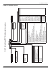
035-19084-001-D-0504 ECONOMIZER / MOTORIZED DAMPER FIXED OUTDOOR INTAKE AIR AND POWER EXHAUST RAIN HOODS (See detail Y) BLOWER MOTOR BLOWER COMPARTMENT ACCESS ACCESS (Auxillary) BLOWER ACCESS 180-19/32 COMPRESSOR ACCESS (See detail X) 48-1/4 DOT PLUG (For pressure drop reading) GAS OR ELECTRIC HEAT ACCESS COIL GUARD KIT VENT AIR OUTLET HOODS 21.
035-19084-001-D-0504 DUCT COVERS - Units are shipped with the bottom duct openings covered. An accessory flange kit is available for connecting side ducts. For bottom duct applications: 1. Remove the side panels from the supply and return air compartments to gain access to the bottom supply and return air duct covers. 2. Remove and discard the bottom duct covers (Duct openings are closed with sheet metal covers except when the unit includes a power exhaust option.
035-19084-001-D-0504 TABLE 14: DR180 BLOWER PERFORMANCE - STANDARD DRIVE (COOLING ONLY) ESP 0.2 0.4 0.6 0.8 1 1.2 1.4 1.6 38 CFM 7318 6986 6652 6291 5913 5473 5034 4562 RPM KW BHP CFM 1038 4.872 6.14 7201 1041 4.582 5.78 6901 1043 4.293 5.41 6567 1045 4.003 5.05 6196 1047 3.708 4.68 5788 1050 3.368 4.25 5342 1053 3.065 3.87 4878 1055 2.755 3.47 4382 1 Turn 15 Ton Standard Drive Blower Performance (Horizontal Discharge) RPM KW BHP CFM RPM KW BHP CFM RPM KW BHP CFM 1005 4.55 5.74 6943 976 4.095 5.
035-19084-001-D-0504 TABLE 15: DR180 BLOWER PERFORMANCE - STANDARD DRIVE (GAS HEAT) ESP 0.2 0.4 0.6 0.8 1 1.2 1.4 1.6 CFM 7172 6846 6519 6165 5795 5364 4933 4471 RPM KW BHP CFM 1017 4.775 6.02 7057 1020 4.49 5.66 6763 1022 4.207 5.31 6436 1024 3.923 4.95 6072 1026 3.634 4.58 5672 1029 3.301 4.16 5235 1032 3.004 3.79 4780 1034 2.7 3.
035-19084-001-D-0504 TABLE 16: DR180 BLOWER PERFORMANCE - HIGH STATIC DRIVE (COOLING ONLY) 15 Ton High Static Drive Blower Performance (Horizontal Discharge) CFM RPM KW BHP CFM RPM KW BHP CFM RPM KW BHP CFM RPM KW BHP CFM RPM KW BHP CFM 8109 1124 6.31 8.00 7890 1085 5.70 7.22 7566 1046 5.20 6.59 7196 1006 4.47 5.66 6850 966 3.96 5.01 6436 7821 1125 6.03 7.64 7585 1086 5.34 6.77 7229 1046 4.89 6.20 6857 1006 4.20 5.32 6487 967 3.70 4.68 6070 7513 1127 5.71 7.24 7267 1088 5.12 6.49 6879 1047 4.56 5.
035-19084-001-D-0504 TABLE 17: DR180 BLOWER PERFORMANCE - HIGH STATIC DRIVE (GAS HEAT) 15 Ton High Static Drive Blower Performance (Gas Heat) (Horizontal Discharge) RPM KW BHP CFM RPM KW BHP CFM RPM KW BHP CFM RPM KW BHP CFM RPM KW BHP CFM 1102 6.19 7.84 7732 1063 5.59 7.08 7415 1025 5.10 6.46 7052 986 4.38 5.55 6713 947 3.88 4.91 6307 1103 5.91 7.49 7433 1064 5.23 6.63 7084 1025 4.80 6.08 6720 986 4.12 5.22 6357 948 3.62 4.59 5949 1104 5.60 7.10 7122 1066 5.02 6.36 6741 1026 4.46 5.66 6370 988 3.86 4.
035-19084-001-D-0504 TABLE 18: DR240 BLOWER PERFORMANCE - STANDARD DRIVE (COOLING ONLY) 20 Ton Standard Drive Blower Performance (Horizontal Discharge) RPM KW BHP CFM RPM KW BHP CFM RPM KW BHP CFM RPM KW BHP CFM RPM KW 1025 6.94 8.79 9021 993 6.211 7.87 8684 962 5.59 7.08 8422 929 5.057 6.41 8028 896 4.516 1027 6.629 8.40 8645 995 5.912 7.49 8282 963 5.3 6.72 8022 930 4.781 6.06 7605 897 4.259 1028 6.283 7.96 8262 996 5.606 7.10 7869 965 5 6.34 7585 931 4.482 5.68 7160 898 3.971 1028 5.979 7.58 7859 997 5.
035-19084-001-D-0504 TABLE 19: DR240 BLOWER PERFORMANCE - STANDARD DRIVE (GAS HEAT) 20 Ton Standard Drive Blower Performance (Gas Heat) (Horizontal Discharge) RPM KW BHP CFM RPM KW BHP CFM RPM KW BHP CFM RPM KW BHP CFM RPM KW 1005 6.804 8.62 8844 974 6.089 7.72 8514 943 5.48 6.94 8257 911 4.958 6.28 7871 878 4.427 1007 6.499 8.24 8475 975 5.796 7.35 8120 944 5.199 6.59 7865 912 4.687 5.94 7456 879 4.175 1008 6.16 7.81 8100 976 5.496 6.96 7715 946 4.903 6.21 7436 913 4.394 5.57 7020 880 3.893 1008 5.862 7.
035-19084-001-D-0504 TABLE 20: DR240 BLOWER PERFORMANCE - HIGH STATIC DRIVE (COOLING ONLY) 20-Ton Blower Performance (Horizontal Discharge) (High Static Option)(Cooling Only) ESP CFM RPM KW BHP CFM RPM KW BHP CFM RPM KW BHP CFM RPM KW BHP CFM RPM KW BHP CFM 0.2 10477 1118 9.15 11.64 10161 1086 8.42 10.70 9949 1056 7.76 9.86 9634 1025 7.05 8.96 9232 973 6.43 8.18 8880 0.4 10144 1119 8.82 11.21 9792 1088 8.06 10.24 9589 1057 7.41 9.42 9231 1025 6.75 8.58 8849 974 6.13 7.79 8473 0.6 9826 1121 8.58 10.
035-19084-001-D-0504 TABLE 21: DR240 BLOWER PERFORMANCE - HIGH STATIC DRIVE (GAS HEAT) 20-Ton Blower Performance (Gas Heat) (Horizontal Discharge) (High Static Option) RPM KW BHP CFM RPM KW BHP CFM RPM KW BHP CFM RPM KW BHP CFM RPM KW BHP 1096 8.98 11.4 9962 1065 8.25 10.5 9754 1035 7.61 9.67 9445 1005 6.91 8.79 9051 954 6.31 8.02 1097 8.65 11 9600 1067 7.9 10 9401 1036 7.27 9.24 9050 1005 6.62 8.41 8675 955 6.01 7.64 1099 8.41 10.7 9242 1068 7.55 9.6 9028 1037 6.94 8.82 8678 1006 6.31 8.02 8402 974 5.
035-19084-001-D-0504 TABLE 22: DR300 BLOWER PERFORMANCE - STANDARD DRIVE 25 Ton Blower Performance (Horizontal Discharge) RPM KW BHP CFM RPM KW BHP CFM RPM KW BHP CFM RPM KW BHP 996 7.1 9.04 8800 959 6.1 7.79 8700 950 5.9 7.53 8250 913 4.95 6.97 997 6.6 8.43 8150 960 5.6 7.15 8010 950 5.4 6.89 7540 915 4.57 6.44 998 6.1 7.79 7510 961 5.1 6.51 7330 952 4.9 6.25 6820 916 4.09 5.77 1000 5.6 7.15 6830 962 4.6 5.87 6570 953 4.4 5.62 5990 916 3.52 4.96 1000 5.1 6.51 6140 964 4.2 5.36 5850 954 3.8 4.
035-19084-001-D-0504 TABLE 23: DR300 BLOWER PERFORMANCE - HIGH STATIC DRIVE 25 Ton Blower Performance (Horizontal Discharge) (High Static Option) ESP CFM RPM KW BHP CFM RPM KW BHP CFM RPM KW BHP CFM RPM KW BHP CFM 0.4 11600 1200 12.5 16.0 11175 1164 11.5 14.7 10620 1127 10.4 13.3 10500 1092 9.2 11.7 9875 0.6 11060 1201 11.8 15.1 10600 1166 10.8 13.8 10100 1131 9.7 12.4 9980 1095 8.6 11.0 9320 0.8 10500 1203 11.1 14.2 10100 1169 10.2 13.0 9520 1132 9.1 11.6 9360 1097 8 10.2 8600 1 9930 1205 10.4 13.
035-19084-001-D-0504 TABLE 24: STATIC RESISTANCES1 RESISTANCE, IWG CFM DESCRIPTION 15 TON 20 TON 25 TON 4500 6000 7200 6000 8000 9400 7500 10000 0.1 0.1 0.1 0.1 0.1 0.1 0.11 0.11 0.11 18 KW 0.3 0.35 0.3 0.35 0.40 0.45 0.31 0.45 0.55 36 KW 0.32 0.4 0.37 0.4 0.48 0.5 0.38 0.5 0.6 54 KW 0.38 0.45 0.49 0.45 0.52 0.57 0.5 0.6 0.7 72 KW 0.38 0.45 0.49 0.45 0.52 0.57 0.5 0.6 0.7 ECONOMIZER OPTION 0.1 0.1 0.1 0.1 0.1 0.1 0.06 0.11 0.
035-19084-001-D-0504 DR180 Charging Chart Outdoor TempºF 350 115º 330 Discharge Pressure (psi) 310 105º 290 270 95º 250 85º 230 210 75º 190 65º 170 150 65 70 75 80 85 90 95 Suction Pressure (psi) Both fans must be running when charging the unit. One fan may switch off at low ambient temperatures making this chart inaccurate.
035-19084-001-D-0504 DR300 Charging Chart Outdoor Temp (ºF) 350 115º Discharge pressure (psi) 330 310 105º 290 95º 270 250 85º 230 75º 210 65º 190 170 150 55 60 65 70 75 80 85 Suction pressure (psi) Both fans must be running when charging the unit. One fan may switch off at low ambient temperatures making this chart inaccurate. FIGURE 15 - CHARGING CHART - 25 TON PHASING Check for proper compressor rotation.
035-19084-001-D-0504 Note the following: 1. The supply air CFM must be within the limitations shown in the Unit Application Data Table 1. 2. Pulleys can be adjusted in half turn increments. 4. Knowing the pressure drop across a dry coil, the actual CFM through the unit can be determined from the curve in Pressure Drop vs. Supply Air CFM Figure 17. 3. The tension on the belt should be adjusted as shown in the Belt Adjustment Figure 16. Start the supply air blower motor.
035-19084-001-D-0504 INTERMITTENT BLOWER With the room thermostat fan switch set to "AUTO" and the system switch set to either the "AUTO" or "HEAT" settings, the blower is energized whenever a cooling or heating operation is requested. The blower is energized after any specified delay associated with the operation. When energized, the indoor blower has a minimum run time of 30 seconds. Additionally, the indoor blower has a delay of 10 seconds between operations.
035-19084-001-D-0504 MOTORIZED OUTDOOR AIR DAMPERS - This system operation is the same as the units with no outdoor air options with one exception. When the "R" to "G" circuit is complete, the motorized damper drives open to a position set by the thumbwheel on the damper motor. When the "R" to "G" circuit is opened, the damper spring returns fully closed. COOLING OPERATION ERRORS Each cooling system is monitored for operation outside of the intended parameters. Errors are handled as described below.
035-19084-001-D-0504 low return air temperature, (opens at 26 ± 5 °F and resets at 38 ± 5°F). 2. A high-pressure switch to protect against excessive discharge pressures due to a blocked condenser coil or a condenser motor failure, (opens at 380 ± 10 psig and resets at 300 ± 10 psig). 3. A low-pressure switch to protect against loss of refrigerant charge, (opens at 7 ± 3 psig and resets at 22 ± 5 psig). The above pressure switches are hard-soldered to the unit.
035-19084-001-D-0504 the unit into the reheat mode. While in the reheat mode, the unit operates both stages of compression and the one reheat coil. Indoor blower operation is initiated upon a call for first stage cooling, second stage cooling or dehumidification. When the room thermostat calls for first stage cooling while there is still a call for dehumidification, no operational change is made. The unit continues to operate both stages of compression with system #1 in the reheat mode.
035-19084-001-D-0504 UCB RHB UNIT CONTROL BOARD REHEAT CONTROL BOARD HUM HUMIDIFY TERMINAL RHR REHEAT RELAY RHTB REHEAT TERMINAL BLOCK FIGURE 19 - REHEAT CONTROLS - PART 1 REHEAT SOLENOID 1 REHEAT SOLENOID 3 REHEAT SOLENOID 2 UCB UNIT CONTROL BOARD RHB REHEAT CONTROL BOARD FIGURE 20 - REHEAT CONTROLS - PART 2 56 Unitary Products Group
035-19084-001-D-0504 Check Valve Piping T TXV HPS Condenser Fan Check Valve Air Flow Air Flow Condenser Coil Indoor Blower FS Air Flow Evaporator Coil Hot Gas Coil Open in Cooling Refrigerant flow in cooling mode Refrigerant flow in reheat mode Bleed Line to clear Suction line the Hot Gas Coil bleed when it is not in use HPS LPS Sol 1 Piping T Accumulator Sol 2 C1 Hot Gas Re-Heat Solenoid Valve (Sol 3) Compressor Open in Reheat FIGURE 21 - SYSTEM PIPING SCHEMATIC ELECTRIC HEATING SE
035-19084-001-D-0504 NOTE: All 240 & 480V heaters are provided with manual reset backup protection limits. These will de-energize the heaters should the primary limit fail to open or the contactors fail to open in a failure mode. HEATING OPERATION ERRORS TABLE 27: LIMIT CONTROL SETTING UNIT (Tons) VOLTAGE 15 20, 25 If the temperature limit opens three times within one hour, it will lock-on the indoor blower motor and a flash code is initiated (See Table 32).
035-19084-001-D-0504 TABLE 28: ELECTRIC HEAT ANTICIPATOR SETPOINTS HEATER KW VOLTAGE SETTING, AMPS TH1 TH2 18 0.29 - 36 0.29 0.29 54 208/230-3-60 0.29 0.58 72 0.29 0.58 18 0.29 - 36 0.29 0.29 54 460-3-60 0.29 0.29 72 0.29 0.29 18 0.29 - 36 0.29 0.29 0.29 0.29 0.29 0.29 54 575-3-60 72 GAS HEATING SEQUENCE OF OPERATIONS The following sequence describes the operation of the gas heat section.
035-19084-001-D-0504 When the thermostat has been satisfied, heating calls are ceased. The GV is immediately de-energized. The blower is de-energized after the fan off delay for heating has elapsed. The draft motor performs a 25-second post purge. GAS HEATING OPERATION ERRORS TEMPERATURE LIMIT If the UCB senses zero volts from the high temperature limit, the indoor blower motor is immediately energized.
035-19084-001-D-0504 START-UP (COOLING) TABLE 29: LIMIT CONTROL SETTING CAPACITY, MBH UNITS (Tons) INPUT OUTPUT LIMIT CONTROL OPENS, ºF 15, 20, 25 300 240 195 15, 20, 25 400 320 195 PRESTART CHECK LIST After installation has been completed: 1. Check the electrical supply voltage being supplied. Be sure that it is the same as listed on the unit nameplate. 2. Set the room thermostat to the off position. IG N . C O N T R O L # 2 3. Turn unit electrical power on. IG N . C O N T R O L # 1 4.
035-19084-001-D-0504 SHUT DOWN 1. Set the thermostat to highest temperature setting. 1. Check for gas leaks in the unit piping as well as the supply piping. 2. Turn off the electrical power to the unit. START-UP (GAS HEAT) PRE-START CHECK LIST Complete the following checks before starting the unit. 1. Check the type of gas being supplied. Be sure that it is the same as listed on the unit nameplate. 2. Make sure that the vent and combustion air hoods have been properly installed.
035-19084-001-D-0504 Adjust as follows: 3. Remove the gas piping closure panel. 1. Remove the cap on the regulator. It’s located next to the push-on electrical terminals. 4. Disconnect wiring to the gas valves and spark ignitors. Remove the manifold-burner gas valve assembly by lifting up and pulling back. 2. To decrease the gas pressure, turn the adjusting screw counterclockwise. 3. To increase the gas pressure, turn the adjusting screw clockwise.
035-19084-001-D-0504 TABLE 31: GAS RATE - CUBIC FEET PER HOUR Seconds for One Rev. Size of Test Dial 1/2 cu. ft. 1 cu. ft. 4 6 8 10 450 300 228 180 900 600 450 360 12 14 16 18 20 150 129 113 100 90 300 257 225 200 180 22 24 26 28 82 75 69 64 164 150 138 129 COOLING TROUBLESHOOTING GUIDE Example: By actual measurement, it takes 13 seconds for the hand on the 1cubic foot dial to make a revolution with just a 300,000 Btuh furnace running.
035-19084-001-D-0504 protection. Cancel any thermostat calls and set the fan switch to AUTO. Wait for the internal overload to reset. Test again when cool. 5. If M3 is not pulled in, check for 24 volts at the M3 coil. If 24 volts are present at M3 but M3 is not pulled in, replace the contactor. 6. Failing the above, if there is line voltage supplied at M3, M3 is pulled in, and the supply air blower motor still does not operate, replace the motor. 7.
035-19084-001-D-0504 on the UCB. The UCB will flash the last five alarms on the LED. If the compressor is locked out, cancel any call for cooling. This will reset any compressor lock outs. NOTE: While the above step will reset any lockouts, compressor #1 may be held off for the ASCD. See the next step. 10. If 24 volts is present at the UCB Y1 terminal and none of the switches are open and the compressor is not locked out, the UCB may have the compressor in an ASCD.
035-19084-001-D-0504 6. If 24 volts is not present at M2, check for 24 volts at the UCB terminal, C2. If 24 volts are present, check for loose wiring between C2 and the compressor contactor. 7. If 24 volts is not present at the C2 terminal, check for 24 volts from the room thermostat at the UCB Y2 terminal. If 24 volts is not present from the room thermostat, check for the following: a. 24 volts at the thermostat Y2 terminal. b. Proper wiring between the room thermostat and the UCB, i.e.
035-19084-001-D-0504 8. If 24 volts are present at the UCB Y1 terminal, the compressor may be out due to an open high-pressure switch, low-pressure switch, or freezestat. Check for 24 volts at the HPS1, LPS1, and FS1 terminals of the UCB. If a switch has opened, there should be a voltage potential between the UCB terminals, e.g. if LPS1 has opened, there will be a 24volt potential between the LPS1 terminals. 9.
035-19084-001-D-0504 NOTE: To find the Btu input, multiply the number of cubic feet of gas consumed per hour by the Btu content of the gas in your particular locality (contact your gas company for this information - it varies widely from city to city.). The furnace may shut down on a high temperature condition during the procedure. If this occurs, the UCB energize the supply air blower motor until the high temperature limit has reset.
035-19084-001-D-0504 5. If the (RW1) relay is not pulled in, check for 24 volts at the (RW1) coil. If 24 volts is present, replace the (RW1) relay. If 24 volts is not present, check for a loose 24 volt connection back to the relay board and check the connections from the room thermostat to the relay board. If all connections are correct, replace the relay board. The draft motor runs but the furnace does not light and the sparker does not spark. 1.
035-19084-001-D-0504 1. Make the same checks and adjustment as described in “PILOT CHECKOUT” page 63. 2. Check the supply pressure as described in “POST START CHECK LIST” page 62. Make adjustments as necessary. 3. Make sure that the pilot burner is not bent or damaged. 4. Make sure that the ground connections at the pilot burner, gas valve and ignitor control are intact. Check the high tension wire for good electrical connection. If all are intact, replace the ignitor module.
TABLE 33: REHEAT CONTROL BOARD FLASH CODES FLASH CODES On Steady DESCRIPTION This is a Control Failure 1 Flash Not Applicable 2 Flashes Hot Gas Reheat is on with Y1 Output (No Call for Cooling) 3 Flashes Y1, Y2, and Hot Gas Reheat is on because of a call for Y1 and Humidistat. See alt operation OFF No Power or Control Failure Subject to change without notice. Printed in U.S.A. Copyright © 2004 by Unitary Products Group. All rights reserved.