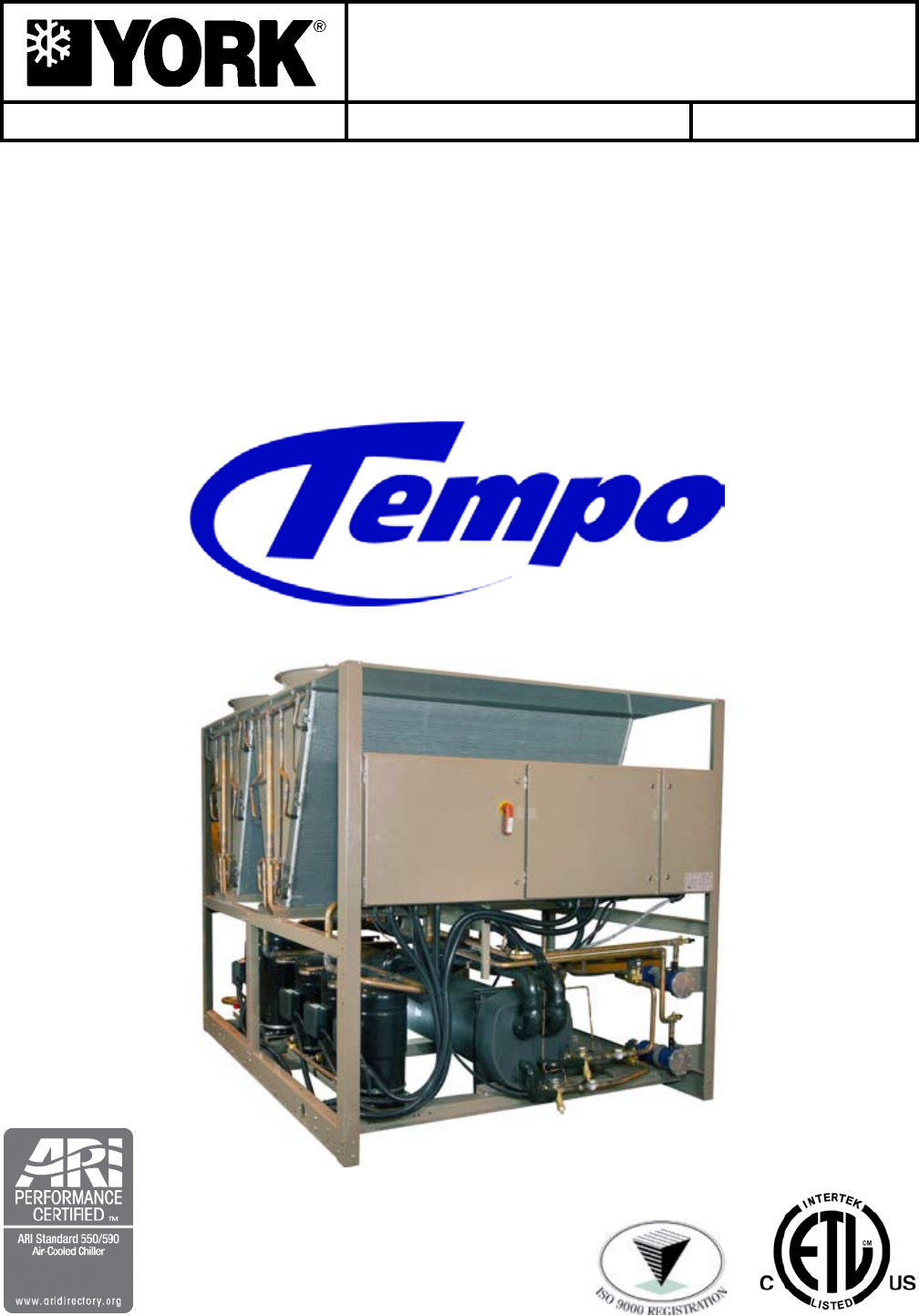
AIR-COOLED LIQUID CHILLERS HERMETIC SCROLL INSTALLATION, OPERATION, Maintenance Replaces 150.72-nm1 (308) Form 150.72-NM1 (908) 035-21911-000 YLAA0070 - YLAA0175 AIR-COOLED SCROLL CHILLERS MICROCHANNEL CONDENSER COILS STYLE A (60 Hz) 70 - 175 TON 246-613 KW Interim GS560418.
FORM 150.72-NM1 (908) IMPORTANT! Read BEFORE PROCEEDING! GENERAL SAFETY GUIDELINES This equipment is a relatively complicated apparatus. During installation, operation, maintenance or service, individuals may be exposed to certain components or conditions including, but not limited to: refrigerants, oils, materials under pressure, rotating components, and both high and low voltage. Each of these items has the potential, if misused or handled improperly, to cause bodily injury or death.
FORM 150.72-NM1 (908) CHANGEABILITY OF THIS DOCUMENT In complying with YORK’s policy for continuous product improvement, the information contained in this document is subject to change without notice. While YORK makes no commitment to update or provide current information automatically to the manual owner, that information, if applicable, can be obtained by contacting the nearest YORK Engineered Systems Service office.
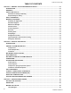
TABLE OF CONTENTS FORM 150.72-NM1 (908) SECTION 1 – GENERAL CHILLER INFORMATION & SAFETY.......................................................................12 INTRODUCTION..........................................................................................................................................12 WARRANTY.................................................................................................................................................12 SAFETY AND QUALITY.....................
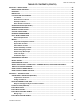
TABLE OF CONTENTS (cont’d) FORM 150.72-NM1 (908) SECTION 4 – INSTALLATION............................................................................................................................34 INSTALLATION CHECKLIST.......................................................................................................................34 HANDLING...................................................................................................................................................
FORM 150.72-NM1 (908) TABLE OF CONTENTS (cont’d) ELECTRICAL NOTES AND LEGEND.........................................................................................................62 WIRING DIAGRAMS....................................................................................................................................64 Elementary Wiring Diagrams...............................................................................................................
FORM 150.72-NM1 (908) TABLE OF CONTENTS (cont’d) PREPARATION – POWER ON..................................................................................................................107 Switch Settings...................................................................................................................................107 Compressor Heaters..........................................................................................................................107 Water System...............
FORM 150.72-NM1 (908) TABLE OF CONTENTS (cont’d) SCHEDULE/ADVANCE DAY KEY.............................................................................................................130 PROGRAM KEY.........................................................................................................................................132 System Trip Volts................................................................................................................................133 Unit Trip Volts.........
FORM 150.72-NM1 (908) TABLE OF CONTENTS (cont’d) CHECKING INPUTS AND OUTPUTS........................................................................................................161 Digital Inputs.......................................................................................................................................161 Analog Inputs – Temperature............................................................................................................161 Outside Air Sensor.................
FORM 150.72-NM1 (908) list of figures Fig. 1 – unit components fRONT.......................................................................................................21 Fig. 2 – unit components SIDE...........................................................................................................22 Fig. 3 – power panel components...................................................................................................23 Fig. 4 – power panel / control components........................
FORM 150.72-NM1 (908) list of tables table 1 – Temperatures and Flows...............................................................................................42 table 2 – VOLTAGE limitations...........................................................................................................42 table 3 – Ethylene & Propylene Glycol Correction Factors..........................................43 table 4 – PHYSICAL DATA (ENGLISH).......................................................................
General Chiller Introduction & Safety FORM 150.72-NM1 (908) SECTION 1 – GENERAL CHILLER INFORMATION & SAFETY INTRODUCTION YORK YLAA0070 - 0175 (70 -175 ton, 246 - 613kW) chillers are manufactured to the highest design and construction standards to ensure high performance, reliability and adaptability to all types of air conditioning installations.
FORM 150.72-NM1 (908) • Manufactured in facility registered to ISO 9002. 1 • OSHA – Occupational Safety and Health Act. In addition, the chillers conform to Underwriters Laboratories (U.L.) for construction of chillers and provide U.L./cU.L. Listing Label. Responsibility for Safety Every care has been taken in the design and manufacture of the unit to ensure compliance with the safety requirements listed above.
General Chiller Introduction & Safety FORM 150.72-NM1 (908) General Access Refrigerants and Oils There are a number of areas and features, which may be a hazard and potentially cause injury when working on the unit unless suitable safety precautions are taken.
FORM 150.72-NM1 (908) SECTION 2 – PRODUCT DESCRIPTION 2 GS560418.JPG INTRODUCTION YORK YLAA Air-Cooled Scroll Chillers provide chilled water for all air conditioning applications using central station air handling or terminal units. They are completely self-contained and are designed for outdoor (roof or ground level) installation.
Product Description The evaporator is constructed, tested and stamped in accordance with applicable sections of ASME pressure vessel code for minimum 450 PSIG (3103 kPa) refrigerant side design working pressure and 150 PSIG (1034 kPa) water side design working pressure A strainer with a mesh size between .5 and 1.5 mm (40 mesh) is recommended upstream of the heat exchanger to prevent clogging from water system debris.
FORM 150.
Product Description FORM 150.72-NM1 (908) ACCESSORIES AND OPTIONS Power Options Control Options COmpRESSOR pOWER CONNECTIONS – Singlepoint terminal block connection(s) are provided as standard. The following power connections are available as options. (See electrical data for specific voltage and options availability.) (Factory-mounted) AmbIENT KIT (LOW) – Units will operate to 25.0°F (-3.9°C). This accessory includes all necessary components to permit chiller operation to 0°F (-18°C).
FORM 150.72-NM1 (908) Condenser and Cabinet Options DX COOLER 300 (21 bAR) pSIG DWp WATERSIDE – The waterside will be of 300 PSIG (21 bar) instead of the standard 150 PSIG DWP. 300 PSIG R.F. flanges are included on the DX cooler nozzles. (Factory-mounted) The companion flanges will be field-supplied by others. FLANGES (ANSI/AWWA C-606 COUpLINGS TYpE) – Consists of (2) flange adapters for grooved end pipe (standard 150 psi [10.5 bar] cooler). (Not available on optional DX cooler 300 PSIG DWP waterside.
Product Description FORM 150.72-NM1 (908) SOUND ATTENUATION – One or both of the following sound attenuation options are recommended for residential or other similar sound sensitive locations: COmpRESSOR ACOUSTIC SOUND bLANKET – Each compressor is individually enclosed by an acoustic sound blanket. The sound blankets are made with one layer of acoustical absorbent textile fiber of 5/8” (15mm) thickness; one layer of antivibrating heavy material thickness of 1/8” (3 mm).
FORM 150.72-NM1 (908) UNIT COMPONENTS 2 FAN ASSEMBLIES CONDENSER COIL CONDENSER COILS CONTROL PANEL POWER PANEL POWER PANEL SIGHT GLASS FILTER DRIERS LD13245 COMPRESSORS EVAPORATOR TXV Fig.
Product Description FORM 150.72-NM1 (908) UNIT COMPONENTS (CONT) FAN ASSEMBLIES CONDENSER COILS CONDENSER COILS EVAPORATOR RECEIVERS LD13426 Fig.
FORM 150.72-NM1 (908) CONTROL / POWER PANEL COMPONENTS FAN FUSES FAN CONTACTORS 2 DISCONNECT SWITCH FAN CONTACTOR COMPRESSOR OVERLOADS XTBF1 COMPRESSOR CONTACTORS LD13247 Fig.
Product Description FORM 150.72-NM1 (908) CONTROL / POWER PANEL COMPONENTS (CONT) FAN FUSES FAN CONTACTORS CONTROL RELAY MICROCOMPUTER CONTROL CENTER MICROPANEL DISPLAY KEYPAD COMPRESSOR OVERLOADS XTBC1 XTBC2 COMPRESSOR CONTACTORS XTBF2 MICROBOARD LD13248 Fig.
FORM 150.
Product Description FORM 150.
FORM 150.
Product Description FORM 150.
FORM 150.
Product Description FORM 150.
FORM 150.
Handling and Storage FORM 150.72-NM1 (908) SECTION 3 – HANDLING AND STORAGE DELIVERY AND STORAGE To ensure consistent quality and maximum reliability, all units are tested and inspected before leaving the factory. Units are shipped completely assembled and containing refrigerant under pressure. Units are shipped without export crating unless crating has been specified on the Sales Order.
FORM 150.72-NM1 (908) 3 Typical Lifting Arrangement - 8 Fan Models LD13137 Use spreader bars to avoid lifting chains hitting the chiller. Never lift the chiller using a forklift or by hooking to the top rails. Use only the lifting holes provided. Lifting Instructions are placed on a label on the chiller and on the shipping bag. LD13140 Typical Lifting Arrangement - 4 Fan Models Fig.
Installation FORM 150.72-NM1 (908) SECTION 4 – INSTALLATION To ensure warranty coverage, this equipment must be commissioned and serviced by an authorized YORK service mechanic or a qualified service person experienced in chiller installation.
FORM 150.72-NM1 (908) Ground Level Locations It is important that the units be installed on a substantial base that will not settle. A one piece concrete slab with footers extended below the frost line is highly recommended. Additionally, the slab should not be tied to the main building foundations as noise and vibration may be transmitted. Mounting holes (5/8” dia.) are provided in the steel channel for bolting the unit to its foundation (see DIMENSIONS).
Installation Drain connections should be provided at all low points to permit complete drainage of the cooler and system water piping. A small valve or valves should be installed at the highest point or points in the chilled water piping to allow any trapped air to be purged. Vent and drain connections should be extended beyond the insulation to make them accessible. The piping to and from the cooler must be designed to suit the individual installation.
FORM 150.72-NM1 (908) DUCT WORK CONNECTION General Requirements The following duct work recommendations are intended to ensure satisfactory operation of the unit. Failure to follow these recommendations could cause damage to the unit, or loss of performance, and may invalidate the warranty.
Installation FORM 150.72-NM1 (908) Alarm Status Contacts Load Limit Input Normally‑open contacts are available for each refrigerant system. These normally‑open contacts close when the system is functioning normally. The respective contacts will open when the unit is shut down on a unit fault, or locked out on a system fault. Field connections are at XTBC2 - Terminals 29 to 30 (system 1), and Terminals 31 to 32 (system 2).
FORM 150.72-NM1 (908) SINGLE-POINT SUPPLY CONNECTION – TERMINAL BLOCK, NON-FUSED DISCONNECT SWITCH OR CIRCUIT BREAKER Power Panel Control Panel 14 13 XTBC1 Terminal Block, NF Disconnect SW or Circuit Breaker MICROPANEL 4 Flow Switch GRD 1L1 1L2 1L3 L 2 XTBC2 See electrical note 9 Field Provided Unit Power Supply Field Provided 120-1-60 Micropanel Power Supply if Control Transformer not supplied. Field supplied control power wiring must be run in separate grounded conduit.
Installation FORM 150.72-NM1 (908) USER CONTROL WIRING INPUTS AA+ 14 13 50 13 21 13 20 13 19 13 18 13 51 13 INTERNAL WIRING TO OPTIONAL REMOTE TEMP. RESET BOARD FLOW SWITCH REMOTE UNLOAD STEP 1 PWM REMOTE TEMP RESET INTERNAL WIRING TO 2-KCR CONTROL RELAY INTERNAL WIRING TO 1-KCR CONTROL RELAY REMOTE START / STOP XTBC1 LD13130 All externally supplied contacts must be capable of switching 24 VDC / 115 VAC. Gold contacts are recommended.
FORM 150.72-NM1 (908) USER CONTROL WIRING OUTPUTS Normally jumpered. Can be used as EMERGENCY STOP contacts from an external source.
Technical Data FORM 150.
FORM 150.72-NM1 (908) HEAT EXCHANGER FLOW, GPM YLAA Evaporator Pressure Drop (IP Units) 100.0 D Pressure Drop (ft H2O) B F 10.0 A 5 E C 1.
Technical Data FORM 150.72-NM1 (908) PHYSICAL DATA (ENGLISH) YLAA0070_ – YLAA0175_ 60Hz table 4 – PHYSICAL DATA (ENGLISH) Model Number YLAA Refrigerant R-410A STANDARD EFFICIENCY UNITS 0070SE 0080SE 0090SE 0100SE 0115SE 0120SE 0135SE 0150SE 0155SE 0170SE Nominal Tons, R-410A 71.8 77.7 85.8 95.8 113.9 119.7 127.3 140.4 143.1 167.9 Length 116.1 116.1 116.1 142.7 142.7 142.7 187.7 187.7 187.7 232.7 Width 88.0 88.0 88.0 88.0 88.0 88.0 88.0 88.0 88.0 88.0 Height 94.
FORM 150.72-NM1 (908) Model Number YLAA HIGH EFFICIENCY UNITS 0091HE 0101HE 0125HE 0141HE 0156HE 0175HE 88.1 98.3 117.0 130.6 145.6 174.2 142.7 142.7 187.7 187.7 232.7 232.7 88.0 88.0 88.0 88.0 88.0 88.0 94.2 94.2 94.2 94.2 94.2 94.2 2 2 2 2 2 2 59 / 55 2.76 / 2.76 5334 55 / 71 3.28/3.33 5569 75 / 71 3.33/3.33 6485 83 / 73 4.99 / 2.76 6997 90 / 82 4.99 / 3.33 7582 94 / 92 4.99 / 4.
Technical Data FORM 150.
FORM 150.72-NM1 (908) ELECTRICAL NOTES NOTES: 1. Minimum Circuit Ampacity (MCA) is based on 125% of the rated load amps for the largest motor plus 100% of the rated load amps for all other loads included in the circuit, per N.E.C. Article 430‑24. If the optional Factory Mounted Control Transformer is provided, add the following MCA values to the electrical tables for the system providing power to the transformer: ‑17, add 2.5 amps; ‑28, add 2.3 amps; ‑40, add 1.5 amps, ‑46, add 1.3 amps; ‑58, add 1 amps.
Technical Data FORM 150.
FORM 150.72-NM1 (908) SYSTEM # 2 COMPR 1 COMPR 2 COMPR 3 COND FANS RLA LRA RLA LRA RLA LRA QTY FLA LRA 51.3 51.3 26.9 23.1 19.9 51.3 51.3 26.9 23.1 19.9 109.6 109.6 69.2 54.5 49.4 109.6 109.6 69.2 54.5 49.4 109.6 109.6 69.2 54.5 49.4 109.6 109.6 69.2 54.5 49.4 109.6 109.6 69.2 54.5 49.4 109.6 109.6 69.2 54.5 49.4 300 300 139 150 109 300 300 139 150 109 599 599 358 310 239 599 599 358 310 239 599 599 358 310 239 599 599 358 310 239 599 599 358 310 239 599 599 358 310 239 51.3 51.3 26.9 23.
Technical Data FORM 150.
FORM 150.72-NM1 (908) COMPR 1 RLA LRA 109.6 599 109.6 599 69.2 358 54.5 310 49.4 239 109.6 599 109.6 599 69.2 358 54.5 310 49.4 239 109.6 599 109.6 599 69.2 358 54.5 310 49.4 239 109.6 599 109.6 599 69.2 358 54.5 310 49.4 239 109.6 599 109.6 599 69.2 358 54.5 310 49.4 239 109.6 599 109.6 599 69.2 358 54.5 310 49.4 239 COMPR 2 RLA LRA 55.8 425 55.8 425 36.0 239 26.9 187 23.7 148 109.6 599 109.6 599 69.2 358 54.5 310 49.4 239 110 599 110 599 69.2 358 54.5 310 49.4 239 55.8 425 55.8 425 36 239 26.9 187 23.
Technical Data FORM 150.
FORM 150.
Technical Data FORM 150.72-NM1 (908) ELECTRICAL DATA W/ PUMPS CHILLER MODEL YLAA0070 SE YLAA0070 SE YLAA0070 SE YLAA0070 SE YLAA0070 SE YLAA0080 SE YLAA0080 SE YLAA0080 SE YLAA0080 SE YLAA0080 SE 54 MIN N/F DISC SW PUMP FLA MINIMUM CIRCUIT AMPS LUG MIN DUAL ELEM FUSE & MIN CB MAX DUAL ELEM FUSE & MAX CB RATING SIZE 208 15.4 366 600 230 13.9 364 600 S6-600 S6: (2) 250kcmil - 500kcmil 400 400 S6-600 S6: (2) 250kcmil - 500kcmil 400 8.
FORM 150.72-NM1 (908) SYSTEM # 1 COMPR 1 COMPR 2 SYSTEM # 2 COMPR 3 COND FANS QTY FLA LRA RLA 51.3 LRA 300 RLA 51.3 LRA 300 RLA 51.3 LRA 300 2 7.6 51.3 300 51.3 300 51.3 300 2 7.4 26.9 139 26.9 139 26.9 139 2 23.1 150 23.1 150 23.1 150 19.9 109 19.9 109 19.9 51.3 300 51.3 300 51.3 300 51.3 300 26.9 139 26.9 23.1 150 COMPR 1 COMPR 2 COMPR 3 COND FANS QTY FLA LRA 30.9 RLA 51.3 LRA 300 RLA 51.3 LRA 300 RLA 51.3 LRA 300 2 7.6 30.9 37.0 51.
Technical Data FORM 150.72-NM1 (908) ELECTRICAL DATA W/ PUMPS (continued) CHILLER MODEL YLAA0090 SE YLAA0090 SE YLAA0090 SE YLAA0090 SE YLAA0090 SE YLAA0091 HE YLAA0091 HE YLAA0091 HE YLAA0091 HE YLAA0091 HE 56 MIN N/F DISC SW PUMP FLA MINIMUM CIRCUIT AMPS LUG MIN DUAL ELEM FUSE & MIN CB MAX DUAL ELEM FUSE & MAX CB RATING SIZE 208 15.4 406 600 230 13.9 404 600 S6-600 S6: (2) 250kcmil - 500kcmil 450 500 S6-600 S6: (2) 250kcmil - 500kcmil 450 8.
FORM 150.72-NM1 (908) SYSTEM # 1 COMPR 1 COMPR 2 SYSTEM # 2 COMPR 3 COND FANS QTY FLA LRA RLA 55.8 LRA 425 RLA 55.8 LRA 425 RLA 55.8 LRA 425 2 7.6 55.8 425 55.8 425 55.8 425 2 7.4 36.0 239 36.0 239 36.0 239 2 26.9 187 26.9 187 26.9 187 23.7 148 23.7 148 23.7 55.8 425 55.8 425 55.8 425 55.8 425 36.0 239 36.0 26.9 187 23.7 COMPR 1 COMPR 2 COMPR 3 RLA LRA COND FANS QTY FLA LRA 30.9 RLA 109.6 LRA 599 RLA 55.8 LRA 425 2 7.6 30.9 37.0 109.
Technical Data FORM 150.72-NM1 (908) ELECTRICAL DATA W/ PUMPS (continued) CHILLER MODEL YLAA0101 HE YLAA0101 HE YLAA0101 HE YLAA0101 HE YLAA0101 HE YLAA0115 YLAA0120 SE YLAA0115 YLAA0120 SE YLAA0115 YLAA0120 SE YLAA0115 YLAA0120 SE YLAA0115 YLAA0120 SE 58 MIN N/F DISC SW PUMP FLA MINIMUM CIRCUIT AMPS LUG MIN DUAL ELEM FUSE & MIN CB MAX DUAL ELEM FUSE & MAX CB RATING SIZE 208 21.4 481 600 230 20.
FORM 150.72-NM1 (908) SYSTEM # 1 COMPR 1 COMPR 2 SYSTEM # 2 COMPR 3 COND FANS QTY FLA LRA RLA 55.8 LRA 425 RLA 55.8 LRA 425 RLA 55.8 LRA 425 2 7.6 55.8 425 55.8 425 55.8 425 2 7.4 36.0 239 36.0 239 36.0 239 2 26.9 187 26.9 187 26.9 187 23.7 148 23.7 148 23.7 55.8 425 55.8 425 55.8 425 55.8 36.0 239 26.9 COMPR 1 COMPR 2 COMPR 3 RLA LRA COND FANS QTY FLA LRA 30.9 RLA 109.6 LRA 599 RLA 109.6 LRA 599 4 7.6 30.9 37.0 109.6 599 109.6 599 4 7.
Technical Data FORM 150.72-NM1 (908) ELECTRICAL DATA W/ PUMPS (continued) CHILLER MODEL YLAA0115 SE YLAA0135 SE YLAA0135 SE YLAA0135 SE YLAA0135 SE YLAA0135 SE YLAA0150 YLAA0155 SE YLAA0150 YLAA0155 SE YLAA0150 YLAA0155 SE YLAA0150 YLAA0155 SE 60 MIN N/F DISC SW PUMP FLA MINIMUM CIRCUIT AMPS LUG MIN DUAL ELEM FUSE & MIN CB MAX DUAL ELEM FUSE & MAX CB RATING SIZE 208 27.1 539 600 230 24.
FORM 150.72-NM1 (908) SYSTEM # 1 COMPR 1 COMPR 2 SYSTEM # 2 COMPR 3 RLA LRA COND FANS QTY FLA LRA RLA 109.6 LRA 599 RLA 109.6 LRA 599 3 7.6 109.6 599 109.6 599 3 7.4 69.2 358 69.2 358 3 54.5 310 54.5 310 49.4 239 49.4 239 109.6 599 109.6 599 109.6 109.6 599 109.6 599 69.2 358 69.2 54.5 310 49.4 COMPR 1 COMPR 2 COMPR 3 RLA LRA COND FANS QTY FLA LRA 30.9 RLA 109.6 LRA 599 RLA 109.6 LRA 599 3 7.6 30.9 37.0 109.6 599 109.6 599 3 7.4 37.0 4.
Technical Data FORM 150.
FORM 150.72-NM1 (908) ELECTRICAL NOTES AND LEGEND (CONTINUED) GENERAL a. This drawing is based on IEC symbols. b. Field wiring to be in accordance with the relevant electrical code as well as all other applicable codes and specifications. c. All sources of supply shown on this diagram to be taken from one main isolator, not shown or supplied by YORK. d. e. Green and yellow wire is used for earth, multi-colored cable used for low voltage.
Technical Data FORM 150.72-NM1 (908) WIRING DIAGRAMS Elementary Wiring Diagrams 035-21583-101 REV B LD13143A FIG.
FORM 150.
Technical Data FORM 150.72-NM1 (908) 035-21583-102 REVC LD13145A FIG.
FORM 150.
Technical Data FORM 150.72-NM1 (908) Condenser Fan Mapping and Sequencing LD13147 FIG.
FORM 150.
Technical Data FORM 150.72-NM1 (908) Compressor Wiring 035-21589-106 REVC FIG.
FORM 150.
Technical Data FORM 150.72-NM1 (908) Power Options Connection Diagram 035-21589-103 REVB LD13234A FIG.
FORM 150.
Technical Data FORM 150.72-NM1 (908) Power Panel 035-21589-101 REV B LD13235A FIG.
FORM 150.
Technical Data FORM 150.72-NM1 (908) Dual Pump Wiring FIG.
FORM 150.
Technical Data FORM 150.72-NM1 (908) Wiring FIG.
FORM 150.
Technical Data FORM 150.72-NM1 (908) Micro Panel Conections 035-21589-102 REV C FIG.
FORM 150.
Technical Data FORM 150.72-NM1 (908) DIMENSIONS (ENGLISH) Dimensions – YLAA0070 TO 0091 (English) L H F P D R2 W YLAA Model C2 C1 L H W (width) (length) (height) R1 TYP AVM LOCATIONS F P D C1 C2 R2 R1 I1 I2 I5 I6 A B 13.4 19 84.5 68.3 23 19.5 76.6 19.5 76.6 1.4 85.5 YLAA0070SE 116 88.25 94.2 88.5 42.75 YLAA0080SE 116 88.25 94.2 88.5 42.75 15 18.6 85 68.3 23 19.5 76.6 19.5 76.6 1.4 85.5 YLAA0090SE 116 88.25 94.2 88.5 42.75 16.25 19.6 83 68.
FORM 150.72-NM1 (908) Dimensions – YLAA00100 (English) L 5/8” DIA. MOUNTING HOLES (TYP) B A I1 (TYP) I2 5 H F P D W R2 C1 R1 TYP C2 Water Connection Sizes are shown in the Physical Data Table YLAA Model YLAA0100SE L (length) W (width) H (height) 143.5 88.25 94.2 F 88.5 P 42.75 D 15 C1 18.
Technical Data FORM 150.72-NM1 (908) Dimensions – YLAA00101 TO 0125 (English) L H F P D W C2 C1 R2 R1 (TYP) Water Connection Sizes are shown in the Physical Data Table YLAA0101HE YLAA0115SE YLAA Model L (length) 143.5 143.5 W (width) 88.25 88.25 H (height) 94.2 94.2 F 88.5 88.5 P 42.75 42.75 D 15 15 C1 18.6 18.6 C2 85 85 R4 NA NA R3 NA NA R2 96 96 R1 23 23 YLAA0120SE 143.5 88.25 94.2 88.5 42.75 YLAA0125HE 187.5 88.25 94.2 88.5 42.75 17.
FORM 150.72-NM1 (908) Dimensions – Ylaa0135 - 0155 (English) L Water connection sizes are shown in Physical Data (Table 4). H F P D R2 W YLAA Models C1 R1 C2 YLAA0135SE L (length) 187.5 W (width) 88.25 H (height) 94.2 F 88.5 P 42.75 D 16.25 C1 19.6 C2 83 R4 NA R3 58 R2 66 R1 39 YLAA0141HE YLAA0150SE 187.5 187.5 88.25 88.25 94.2 94.2 88.5 88.5 42.75 42.75 17.25 16.25 22.13 19.6 102 83 NA NA 58 58 66 66 39 39 YLAA0155SE 187.5 88.25 94.2 88.5 42.75 17.
Technical Data FORM 150.72-NM1 (908) Dimensions – Ylaa0156 - 0175 (English) L 5/8" DIA. MOUNTING HOLES (TYP) B A I2 I1 (TYP) I3 H F P D R2 C1 W R1 (TYP) C2 YLAA Model L (length) W (width) H (height) F P D C1 C2 R4 R3 R2 R1 YLAA0156HE 232.7 88.25 94.2 88.5 42.75 16.25 19.6 83 58.0 43 83 23 YLAA0170SE 232.7 88.25 94.2 88.5 42.75 16.25 19.6 83 58.0 43 83 23 YLAA0175HE 232.7 88.25 94.2 88.5 42.75 17.25 22.13 102 58.
FORM 150.72-NM1 (908) (2 m) TECHNICAL DATA – CLEARANCES 5 (2 m) (2 m) (1.3 m) LD13243 NOTES: 1. No obstructions allowed above the unit. 2. Only one adjacent wall may be higher than the unit. 3. Adjacent units should be 10 feet (3 Meters) apart. FIG.
Technical Data FORM 150.72-NM1 (908) Weight Distribution and Isolator Mounting Positions General Weights of specific chiller models vary significantly as options are added. As a result, total weights, weights at individual isolator positions, and actual isolator selection at each position cannot be published due to the vast number of possible combinations. This information will be available when the specific chiller/ option selection is made from the local YORK sales office.
FORM 150.
Technical Data FORM 150.72-NM1 (908) Isolator Locations B I1, 15 I, I5 TYP YLAA Model I1 I2 A I2, I6 TYP TYP AVM LOCATIONS I3 I4 I5 I6 I7 I8 A B YLAA0070SE 19.5 76.6 19.5 76.6 1.36 85.5 YLAA0080SE 19.5 76.6 19.5 76.6 1.36 85.5 YLAA0090SE 19.5 76.6 19.5 76.6 1.36 85.5 YLAA0091HE 7.6 117.2 7.6 117.2 1.36 85.5 B I1, 15 I, I5 TYP TYP YLAA Model A I3, I7 TYP I2, I6 TYP AVM LOCATIONS YLAA0100SE I1 7.6 I2 117.2 YLAA0101HE 7.6 YLAA0115SE 7.
FORM 150.72-NM1 (908) ISOLATOR LOCATIONS (Continued) 5 B I1, 15 I,TYP I5 TYP YLAA Model YLAA0070SE A I3, I7 TYP I2, I6 TYP AVM LOCATIONS I1 I2 19.5 76.6 I3 I4 I5 I6 19.5 76.6 I7 I8 A B 1.36 85.5 YLAA0080SE 19.5 76.6 19.5 76.6 1.36 85.5 YLAA0090SE 19.5 76.6 19.5 76.6 1.36 85.5 YLAA0091HE 7.6 117.2 7.6 117.2 1.36 85.5 NOTE: All dimensions in inches.
Technical Data FORM 150.72-NM1 (908) ISOLATOR LOCATIONS (Continued) I2, I6 I1, I5 I4, I8 I3, I7 B YLAA Model CONTROL PANEL END A AVM LOCATIONS YLAA0156HE I1 7.6 I2 69.03 I3 72.5 I4 63.6 I5 7.6 I6 69.03 I7 72.5 I8 63.6 A 1.36 B 85.5 YLAA0170SE 7.6 69.03 72.5 63.6 7.6 69.03 72.5 63.6 1.36 85.5 YLAA0175HE 7.6 69.03 72.5 63.6 7.6 69.03 72.5 63.6 1.36 85.5 NOTE: All dimensions in inches.
FORM 150.72-NM1 (908) ISOLATOR INFORMATION FOR Units shipped on or after June 15, 2008 One Inch Deflection Spring Isolator Cross-reference CP 5/8" Ø1/2" H" 5 C" T" B" L" D" W" Mount Type LD13759A Dimension Data (Inches) W D L B C T H CP1 3 5/8 7-3/4 6-1/2 4-3/4 1/2 5-5/8 CP2 3 5/8 10-1/2 9-1/4 7-3/4 9/16 6 MODEL NUMBER COLOR CODE CP-1D-510 BLACK CP-1D-900 CP-1D-1200 (LBS.
Technical Data FORM 150.72-NM1 (908) One Inch Deflection Spring Isolators Installation Instructions Units shipped on or after June 15, 2008 1. READ INSTRUCTIONS IN THEIR ENTIRETY BEFORE BEGINNING INSTALLATION. 2. ISOLATORS ARE SHIPPED FULLY ASSEMBLED AND ARE TO BE POSITIONED IN ACCORDANCE WITH THE SUBMITTAL DRAWINGS OR AS OTHERWISE RECCOMENDED. 3. SET ISOLATORS ON FLOOR, HOUSEKEEPING PAD OR SUBBASE, ENSURING THAT ALL ISOLATORS CENTERLINES MATCH THE EQUIPMENT MOUNTING HOLES.
FORM 150.72-NM1 (908) Seismic Isolator Cross-reference Units shipped on or after June 15, 2008 Y2RS 1-1/8" 5" 5/8" 2-3/4" 2-3/4" 12" 3/8" GAP 5/8-11UNC TYP. (4) Ø3/4" TYP.(4) 5 3/4" 7/8" 14" 1/2" LIMIT STOP & NUT 8-3/8" OPER. HEIGHT 12-1/4" 3-1/2" 3/8" 5" NOTES: 1. ALL DIMENSIONS ARE IN INCHES, INTERPRET PER ANSI Y14. 2. STANDARD FINISH: HOUSING-POWDER COATED (COLOR:BLACK), SPRING-POWDER COATED (COLOR: SEE T HARDWARE ZINC-ELECTROPLATE. 3.
Technical Data FORM 150.72-NM1 (908) Seismic Isolator Installation and Adjustment Units shipped on or after June 15, 2008 1. READ INSTRUCTIONS IN THEIR ENTIRETY BEFORE BEGINNING INSTAL LATION. 2.ISOLATORS ARE SHIPPED FULLY ASSEMBLED AND ARE TO BE POSITIONED IN ACCORDANCE WITH THE SUBMITTAL DRAWINGS OR AS OTHERWISE RECOMMENDED. 3. SET ISOLATORS ON FLOOR, HOUSEKEEPING PAD, OR SUB-BASE, ENSURING THAT ALL ISOLATOR CENTERLINES MATCH THE EQUIPMENT MOUNTING HOLES.
FORM 150.72-NM1 (908) Duralene Isolator Cross-reference Units shipped on or after June 15, 2008 RD-Style Isolators DW CD MOLDED DURULENE HF ø AD THRU TYP 2 PLACES BT AL 5 W L Notes: 1. All dimensions are inches, interpreted per ANSI Y14. 2. Refer to Page 98 for installation instructions. 3. Mount molded in weather resistant duralene compound as standard. Also available in other materials such as natural rubber, extreme high temperature silicone, high-damped silicone, nitrile and EDPM. 4.
Technical Data FORM 150.72-NM1 (908) Installation of Durulene Vibration Isolators Units shipped on or after June 15, 2008 1. READ INSTRUCTIONS IN THEIR ENTIRETY BEFORE BEGINNING INSTALLATION. 2. ISOLATORS ARE SHIPPED FULLY ASSEMBLED AND ARE TO BE POSITIONED IN ACCORDANCE WITH THE SUBMITTAL DRAWINGS OR AS OTHERWISE RECOMMENDED. 3. SET ISOLATORS ON FLOOR, HOUSEKEEPING PAD, OR SUB-BASE, ENSURING THAT ALL ISOLATOR CENTERLINES MATCH THE EQUIPMENT MOUNTING HOLES.
FORM 150.72-NM1 (908) Isolator information for units shipped before June 15, 2008 SLRS Seismic Isolator Specifications "D" Tap - 4 Holes unless otherwise requested Vertical Limit Stops-Out of contact during normal operation E E E E H MBD -Max Bolt Diameter Rubber Snubbing Collar T 5 HCL L HCW W Lower Restraining Nut Adjustment Bolt LD10509 Non-Skid Neoprene PadInternal Enclosed Neoprene Pad can be removed if mounts are welded Steel Acoustical into position.
Technical Data FORM 150.72-NM1 (908) SLRS Seismic Isolator Installation and Adjustment Units shipped before June 15, 2008 TO INSTALL AND ADJUST MOUNTS 1. 2. 3. 4. 5. 6. 7. 8. 9. 10. 11. Supports for mountings must be leveled to installation's acceptable tolerances. Mountings not subjected to seismic or wind forces do not require bolting to supports. Mountings subjected to seismic or wind forces must be bolted or welded in position.
FORM 150.72-NM1 (908) One Inch Deflection Spring Isolator Cross-reference Units shipped before June 15, 2008 CIP-XIllustration shows single spring CIP-B or CIP-C mount. Mounting may be operated 1/2" above Free & Operating Height. EQUIPMENT BASE A Dowel Pin is 3/8" dia. for CIP-A & 1/2" thereafter NOTECIP Mounts are not to be used in seismic or wind load applications. FERROUS HOUSING SIDE ACCESS INTERNAL ADJUSTMENT BOLT Turn clockwise to load spring and maintain Free & Operating Height.
Technical Data FORM 150.72-NM1 (908) Installation of 1” Deflection Mounts Units shipped before June 15, 2008 1. Floor or steel frame should be level and smooth. 5. Complete piping and fill equipment with water, refrigerant, etc. 2. For pad installations, isolators do not normally require bolting. If necessary, anchor isolators to floor through bolt holes in the base plate. 6. Turn leveling bolt of first isolator four full revolutions and proceed to each mount in turn.
FORM 150.72-NM1 (908) Neoprene Isolator Cross-reference Units shipped before June 15, 2008 ND-X "CS" Cap Screw D "MBD" Max. Bolt Dia. Steel Plate - Top & Bottom Neoprene covered to prevent corrosion BC H W 5 L T Size ND-C ND-D ND-DS D 2-9/16 3-3/8 3-3/8 H 2-3/ 4 2-3/4 2-3/4 L 5-1/ 2 6-1/4 6-1/4 ENGLISH (Inches) T W 1/4 2-5/16 5/16 4 5/16 4 BC 4-1/8 5 5 CS 1/2-13 x 1 1/2-13 x 1 1/2-13 x 1 MBD 1/ 2 1/ 2 1/ 2 ND-C ND-D ND-DS 65.1 85.7 85.7 69.9 69.9 69.9 139.7 158.8 158.8 SI (mm) 6.4 58.
Technical Data FORM 150.72-NM1 (908) Two Inch Deflection, Seismic Spring Isolator Cross-reference - SLRS Units shipped before June 15, 2008 SLRS-2-C2 has 2 springs. "D" Tap - 4 Holes unless otherwise requested Vertical Limit Stops-Out of contact during normal operation E E E E H MBD -Max Bolt Diameter Rubber Snubbing Collar T HCL L HCW W Lower Restraining Nut Adjustment Bolt Non-Skid Neoprene PadInternal Enclosed Neoprene Pad can be removed if mounts are welded Steel Acoustical into position.
FORM 150.72-NM1 (908) SLRS Seismic Isolator Installation and Adjustment Units shipped before June 15, 2008 TO INSTALL AND ADJUST MOUNTS 1. Supports for mountings must be leveled to installation's acceptable tolerances. 2. Mountings not subjected to seismic or wind forces do not require bolting to supports. 3. Mountings subjected to seismic or wind forces must be bolted or welded in position. 4. If mountings are welded in position, remove lower friction pad before welding. 5.
Commissioning FORM 150.72-NM1 (908) SECTION 6 – COMMISSIONING COMMISSIONING Compressor Oil PREPARATION – POWER OFF The following basic checks should be made with the customer power to the unit switched OFF. To add oil to a circuit – connect a YORK hand oil pump (Part No. 470-10654-000) to the 1/4” oil charging connection on the compressors with a length of clean hose or copper line, but do not tighten the flare nut.
FORM 150.72-NM1 (908) Supply Voltage Verify that the site voltage supply corresponds to the unit requirement and is within the limits given in the Technical Data Section. PREPARATION – POWER ON Perform the commissioning using the detailed checks outlined in the EQUIPMENT START-UP CHECK SHEET as the commissioning procedure is carried out. Apply power to the chiller. Turn ON the option panel circuit breaker if supplied.
Commissioning FORM 150.
FORM 150.72-NM1 (908) table 7 – SETPOINTS ENTRY LIST OPTIONS Display Language Sys 1 Switch Sys 2 Switch Chilled Liquid * Ambient Control Local/Remote Mode Control Mode Display Units * Lead/Lag Control * Fan Control Manual Override Current Feedback ** Soft Start ** Unit Type ** Refrigerant Type ** Expansion Valve Type COOLING SETPOINTS Cooling Setpoint Range EMS-PWM Max. Setpoint PROGRAM Discharge Pressure Cutout Suct. Pressure Cutout Low Amb. Temp.
Commissioning FORM 150.72-NM1 (908) CHECKING SUPERHEAT AND SUBCOOLING The subcooling temperature of each system can be calculated by recording the temperature of the liquid line at the outlet of the condenser and subtracting it from the liquid line saturation temperature at the liquid stop valve (liquid line saturation temp. is converted from a temperature/pressure chart). Assure that superheat is set at a minimum of 10 °F (5.56 °C) with a single compressor running on each circuit. 2.
FORM 150.72-NM1 (908) UNIT OPERATING SEQUENCE The operating sequence described below relates to operation on a hot water start after power has been applied, such as start-up commissioning. When a compressor starts, internal timers limit the minimum time before another compressor can start to 1 minute. 4. Several seconds after the compressor starts, that systems first condenser fan will be cycled on (outdoor air temperature > 25 °F (-4 °C) or discharge pressure).
Unit Controls FORM 150.72-NM1 (908) SECTION 7 – UNIT CONTROLS YORK MILLENNIUM CONTROL CENTER LD13283 INTRODUCTION IPU II and I/O Boards The YORK MicroComputer Control Center is a microprocessor based control system designed to provide the entire control for the liquid chiller. The control logic embedded in the microprocessor based control system will provide control for the chilled liquid temperatures, as well as sequencing, system safeties, displaying status, and daily schedules.
FORM 150.72-NM1 (908) The on-board power supply converts 24 VAC from 75 VA, 120/24 VAC 50/60Hz UL listed class 2 power transformer to +12V, +5V and +3.3V using switching and linear voltage regulators located on the I/O and IPU II boards. These voltages are used to operate integrated circuitry on the board. The 40 character display and unit sensors (transducers and temp sensors) are supplied power for the micro board +5V supply.
Unit Controls FORM 150.72-NM1 (908) “STATUS” KEY 00066VIP Unit Status Pressing the Status key will enable the operator to determine current chiller operating status. The messages displayed will include running status, cooling demand, fault status, external cycling device status. The display will be a single message relating to the highest priority message as determined by the micro. Status messages fall into the categories of General Status and Fault Status.
FORM 150.72-NM1 (908) S Y S 1 N O C O O L L O A D S Y S 2 N O C O O L L O A D This message informs the operator that the chilled liquid temperature is below the point (determined by the setpoint and control range) that the micro will bring on a system or that the micro has not loaded the lead system far enough into the loading sequence to be ready to bring the lag system “ON”. The lag system will display this message until the loading sequence is ready for the lag system to start.
Unit Controls S Y S 1 P U M P I N G D O W N S Y S 2 P U M P I N G D O W N The PUMPING DOWN message indicates that a compressor in the respective system is presently in the process of pumping the system down. When pumpdown is initiated on shutdown, the liquid line solenoid or EEV will close and a compressor will continue to run. When the suction pressure decreases to the suction pressure cutout setpoint or runs for 180 seconds, whichever comes first, the compressor will cycle off.
FORM 150.72-NM1 (908) The internal motor protector opens at 185 °F – 248 °F (85 °C – 120 °C) and auto resets. The mechanical HP switch opens at 585 PSIG +/- 10 PSIG (27.92 barg +/- .69 barg) and closes at 330 PSIG +/- 25 PSIG (22.75 barg +/- 1.72 barg). The compressor is also equipped with a discharge temperature sensor for the purpose of sensing internal scroll temperature.
Unit Controls Unit Safeties Unit safeties are faults that cause all running compressors to be shut down. Unit faults are auto reset faults in that the unit will be allowed to restart automatically after the fault condition is no longer present. U N I T F A U L T : L O W A M B I E N T T E M P The Low Ambient Temp Cutout is a safety shutdown designed to protect the chiller from operating in a low ambient condition.
FORM 150.
Unit Controls FORM 150.72-NM1 (908) DISPLAY/PRINT KEYS 00067VIP The Display/Print keys allow the user to retrieve system and unit information that is useful for monitoring chiller operation, diagnosing potential problems, troubleshooting, and commissioning the chiller. System and unit information, unit options, setpoints, and scheduling can also be printed out with the use of a printer. Both real-time and history information are available.
FORM 150.72-NM1 (908) s y s X s p = 7 2 . 1 p s i g d p = 2 2 7 . 0 p s i g These displays show suction and discharge pressures for each system. The discharge pressure transducer is optional on some models. If the optional discharge transducer is not installed, the discharge pressure would display 0 PSIG (0 barg).
Unit Controls e v a p o r a t o r h e a t e r s t a t u s i s = X X X This display indicates the status of the evaporator heater. The evaporator heater is controlled by ambient air temperature. When the ambient temperature drops below 40 °F the heater is turned on. When the temperature rises above 45 °F the heater is turned off. An under voltage condition will keep the heater off until full voltage is restored to the system.
FORM 150.72-NM1 (908) See the section on Condenser Fan Control in the Unit Operation section for more information. The fifth message displays current as sensed by the optional current feedback circuitry. The display reads out in amps along with the DC feedback voltage from the module. Current is calculated by: 225A • Actual Volts 5 Volts Individual displays will be present for each system, if CURRENT FEEDBACK ONE PER SYSTEM is programmed under the OPTIONS Key.
Unit Controls FORM 150.72-NM1 (908) Print Key The PRINT key allows the operator to obtain a printout of real-time system operating data or a history printout of system data at the “instant of the fault” on the last six faults which occurred on the unit. An optional printer is required for the printout. Operating Data Printout Pressing the PRINT key and then OPER DATA key allows the operator to obtain a printout of current system operating parameters.
FORM 150.72-NM1 (908) See Service And Troubleshooting section for Printer Installation information. History Printout Pressing the PRINT key and then the HISTORY key allows the operator to obtain a printout of information relating to the last 9 Safety Shutdowns which occurred. The information is stored at the instant of the fault, regardless of whether the fault caused a lockout to occur.
Unit Controls A M B I E N T C O N T R O L X X X X X X X X X X Displays the type of Ambient Control; Standard or Low Ambient. L O C A L / R E M O T E M O D E X X X X X X X X X Displays Local or Remote control selection. C O N T R O L MO D E L E A V I N G L I Q U I D Displays the type of chilled liquid control; Leaving or Return.
FORM 150.72-NM1 (908) L E A D S Y S T E M I S S Y S T E M N U M B E R X Displays which system is in the lead at the time of the fault. E V A P o r a t o r h e a t e r s t a t u s I S X X X Displays status of the Evaporator Heater at the time of the fault. E V A P o R A T O R w a t e r p u m p s t a t u s x X X X Displays status of Evaporator Water Pump at the time of fault. Status may read on, off or trip.
Unit Controls FORM 150.72-NM1 (908) “ENTRY” KEYS 00068VIP The Entry Keys allows the user to view, change programmed values. The ENTRY keys consist of an ↑ (UP) arrow key, ↓ (DOWN) arrow key, and an ENTER/ADV key. Up and Down Arrow Keys Used in conjunction with the OPER DATA, HISTORY, COOLING SETPOINTS, SCHEDULE/ADVANCE DAY, OPTIONS and CLOCK keys, the ↑ (UP) and ↓ (DOWN) arrow keys allow the user to scroll through the various data screens.
FORM 150.72-NM1 (908) “SETPOINTS” KEYS 00069VIP Programming of the cooling setpoints, daily schedule, and safeties is accomplished by using the keys located under the SETPOINTS section. The three keys involved are labeled COOLING SETPOINTS, SCHEDULE/ADVANCE DAY, and PROGRAM. Following are instructions for programming the respective setpoints. The same instruction should be used to view the setpoints with the exception that the setpoint will not be changed.
Unit Controls would be displayed in place of the previous message. When in leaving chilled liquid temperature control, the micro will attempt to control the leaving water temperature within the temperature range of the setpoint + or – the range. In the above example, control will be in the range of 43 – 47 °F. Return Chilled Liquid Control s e t p o i n t = 4 5 . 0 ° f r a n g e = + 1 0 . 0 ° F FORM 150.72-NM1 (908) r e m s e t p = 4 4 . 0 ° f r a n g e = + / - 2 .
FORM 150.72-NM1 (908) table 10 – COOLING SETPOINTS, Programmable Limits and Defaults SETPOINT KEY MODE WATER COOLING LEAVING CHILLED LIQUID SETPOINT GLYCOL COOLING* LEAVING CHILLED LIQUID — CONTROL RANGE WATER COOLING RETURNED CHILLED LIQUID SETPOINT GLYCOL COOLING* RETURN CHILLED LIQUID — CONTROL RANGE MAX EMS-REMOTE — TEMPERATURE RESET LOW LIMIT 40.0 °F 4.4 °C 10.0 °F -12.2 °C 1.5 °F 0.8 °C 40.0 °F 4.4 °C 10.0 °F 21.1 °C 4.0 °F 2.2 °C 2 °F 1.0 °C HIGH LIMIT **70.
Unit Controls PROGRAM KEY There are several operating parameters under the PROGRAM key that are programmable. These setpoints can be changed by pressing the PROGRAM key, and then the ENTER/ADV key to enter Program Mode. Continuing to press the ENTER/ADV key will display each operating parameter. While a particular parameter is being displayed, the ↑ (UP) and ↓ (DOWN) arrow keys can be used to change the value. After the value is changed, the ENTER/ADV key must be pressed to enter the data into memory.
FORM 150.72-NM1 (908) This MUST be programmed correctly to assure proper chiller operation. F A N D I F F E R E N T I A L O F F PR E S S U R E = XX X P S I G The Fan Differential Off Pressure is the programmed differential pressure value that is used to stage the condenser fans off, in relation to discharge pressure. Refer to Condenser Fan Control in the UNIT OPERATION section and Tables 19, 20, 21 and 22.
Unit Controls FORM 150.72-NM1 (908) R E M O T E U N I T P R O G R A M M E D = Unit Trip Volts For total chiller high current trip programming on 460VAC chillers: • Add the sum of all the compressor and fan RLA’s in the chiller. • Multiply the sum by 1.25 • Divide by 225A • The resulting voltage is the value that should be programmed. I D X When communications is required with a BAS or OptiView Panel, individual unit IDs are necessary for communications with specific chillers on a single RS485 line.
FORM 150.72-NM1 (908) table 12 – SETPOINTS QUICK REFERENCE LIST Quick Reference Programming Chart Setpoints Section Cooling Setpoints Key (press key to adv.) Schedule/ Advance Day Key Program Mode (press enter to adv.) Local Leaving Water Temp Control (Display Only) Mon. – Sun. & Holiday Schedule Discharge Pressure Cutout Chilled Liquid Setpoint & Range Suction Pressure Cutout Remote Setpoint & Range (Display Only) Low Ambient Temp.
Unit Controls FORM 150.72-NM1 (908) “UNIT” KEYS OPTIONS CLOCK 00070VIP Options Key There are many user programmable options under the OPTIONS key. The OPTIONS key is used to scroll through the list of options by repeatedly pressing the OPTIONS key. After the selected option has been displayed, the ↑ (UP) and ↓ (DOWN) arrow keys are then used to change that particular option. After the option is changed, the ENTER/ADV key must be pressed to enter the data into memory.
FORM 150.72-NM1 (908) Option 4 – Ambient Control Type: A M B I E N T C O N T R O L S T A N D A R D The low ambient cutout is adjustable from 25 °F to 60 °F (-3.9 °C to 15.6 °C). or A M B I E N T C O N T R O L L O W A M B I E N T The low ambient cutout is programmable down to 0 °F (-17.8 °C). A low ambient kit MUST be installed for this option to be chosen. If the kit is NOT installed, and low ambient is selected, low pressure faults and compressor damage may occur.
Unit Controls F A N C O N T R O L A M B I E N T & D S C H P R E S S Do not select this option on R-410A chillers. Option 10 – Manual Override Mode: M A N U A L O V E R R I D E M O D E D I S A B L E D This option allows overriding of the daily schedule that is programmed. MANUAL OVERRIDE MODE – DISABLED indicates that override mode has no effect. or M A N U A L O V E R R I D E M O D E E N A B L E D FORM 150.
FORM 150.72-NM1 (908) Incorrect programming may cause damage to compressors. F L A S H C A R D U P D A T I N G P L E A S E W A I T . . . After the update is completed, an automatic reboot will occur. If an error occurred, the following message will appear with the error code and no reboot will occur: Option 16 – Expansion Valve Type: e x p a n s i o n v a l v e t y p e t h e r m o s t a t i c Expansion valve type, thermostatic or electronic may be selected under Service Mode.
Unit Controls FORM 150.72-NM1 (908) Option 19 – Pump Control: Option 20 – Pump Selection: Pump Control is utilized to operate the optional onboard pump kit or to control an external pump through dry contacts 23 and 24 on Terminal Block XTBC2. To use this option, the following selection should be made in the Service Mode: The displays for this PUMP SELECTION option should only appear if “YORK HYDRO KIT PUMPS = 2” are selected under Option 19. Presently, this option should not be used.
FORM 150.72-NM1 (908) table 13 – UNIT KEYS OPTIONS PROGRAMMING QUICK REFERENCE LIST Options Key (press Options Key to adv.
Unit Operation CAPACITY CONTROL FORM 150.72-NM1 (908) SECTION 8 – UNIT OPERATION To initiate the start sequence of the chiller, all run permissive inputs must be satisfied (flow/remote start/ stop switch), and no chiller or system faults exist. The first phase of the start sequence is initiated by the Daily Schedule Start or any Remote Cycling Device.
FORM 150.72-NM1 (908) The leaving chilled liquid setpoint is programmable from 40 °F to 70 °F (4.4 °C to 21.1 °C) in water chilling mode and from 10 °F to 70 °F (-12.2 °C to 21.1 °C) in glycol chilling mode. In both modes, the cooling range can be from +/-1.5 °F to +/-2.5 °F (+/-.83 °C to 1.39 °C).leaving chilled liquid control LEAVING CHILLED LIQUID CONTROL OVERRIDE TO REDUCE CYCLING To avoid compressor cycling the micro will adjust the setpoint upward temporarily.
Unit Operation Operation Unit FORM 150.72-NM1 (908) As an example of compressor staging (refer to Table 14), a chiller with six compressors using a Cooling Setpoint programmed for 45 °F (7.20 °C) and a Range Setpoint of 10 °F (5.56 °C). Using the formulas in Table 15, the control range will be split up into six (seven including hot gas) segments, with the Control Range determining the separation between segments.
FORM 150.72-NM1 (908) table 15 – Return Chilled Liquid Control for 4 Compressors (6 steps) *STEP 0 1 2 3 4 5 6 COMPRESSOR 0 1 W/HGB 1 NO HGB 2 2 3 4 COMPRESSOR ON POINT SETPOINT SP + CR/8 (Note 1) SP + CR/4 SP + 2*CR/4 (Note 2) SP + 2*CR/4 SP + 3*CR/4 SP + CR COMPRESSOR OFF POINT SETPOINT SETPOINT SP + CR/8 SP + CR/4 SP + CR/4 (Note 3) SP + 2*CR/4 SP + 3*CR/4 Notes: 1. Step 1 is Hot Gas Bypass and is skipped when loading occurs. Hot Gas Bypass operation is inhibited during Pumpdown. 2.
Unit Operation ANTI-RECYCLE TIMER The programmable anti-recycle timer assures that systems do not cycle. This timer is programmable under the PROGRAM key between 300 – 600 seconds. Whenever possible, to reduce cycling and motor heating, the anti-recycle timer should be adjusted to 600 seconds. The programmable anti-recycle timer starts the timer when the first compressor in a system starts. The timer begins to count down.
JOHNSON CONTROLS CONTROL PANEL CONTROL PANEL CONTROL PANEL CONTROL PANEL CONTROL PANEL CONTROL PANEL CONTROL PANEL CONTROL PANEL FORM 150.72-NM1 (908) LD13244 Fig.
Unit Operation FORM 150.
FORM 150.
Unit Operation FORM 150.
FORM 150.
Unit Operation FORM 150.
FORM 150.
Unit Operation FORM 150.
FORM 150.72-NM1 (908) LOAD LIMITING Load Limiting is a feature that prevents the unit from loading beyond the desired value. 2 and 4 compressor units can be load limited to 50%. This would allow only 1 compressor per system to run. 3 and 6 compressor units can be load limited to 33% or 66%. The 66% limit would allow up to 2 compressors per system to run, and the 33% limit would allow only 1 compressor per system to run.
Unit Operation FORM 150.72-NM1 (908) BAS/EMS TEMPERATURE RESET USING A VOLTAGE OR CURRENT SIGNAL The Remote Reset Option allows the Control Center of the unit to reset the chilled liquid setpoint using a 0 ‑ 10VDC input, or a 4‑20mA input connected to XTBC1 terminals A- and A+. Whenever a reset is called for, the change may be noted by pressing the Cooling Setpoints key twice. The new value will be displayed as “REM SETP = XXX °F.
FORM 150.72-NM1 (908) Section 9 – SERVICE AND TROUBLESHOOTING CLEARING HISTORY BUFFERS The history buffers may be cleared by pressing the HISTORY key and then repeatedly pressing the UP arrow key until you scroll past the last history buffer choice. The following message will be displayed: I I N I T I A L I Z E H I S T O R Y E N T E R = Y E S Pressing the ENTER/ADV key at this display will cause the history buffers to be cleared. Pressing any other key will cancel the operation.
Service and Troubleshooting FORM 150.72-NM1 (908) Pressing the ↑ (UP) arrow key will energize the liquid line solenoid valve and “OFF” will change to “ON” in the display as the LLSV is energized. Energizing and de-energizing outputs may be useful during troubleshooting. SERVICE MODE – CHILLER CONFIGURATION After the Outputs are displayed, the next group of displays relate to chiller configuration and start/hour counters.
FORM 150.72-NM1 (908) The digital inputs will display the input connection and ON/OFF status such as: f l o w s w / r e m s t a r t j 13 - 5 i s o n This indicates that the flow switch/remote start input is connected to plug 13- pin 5 (J13-5) on the microboard, and is ON (ON = +30VDC unregulated input, OFF = 0VDC input on digital inputs).
Service and Troubleshooting FORM 150.72-NM1 (908) TB6 TB5 I/O BOARD J15 TB1 TB7 J3 TB8 J5 IPU BOARD TB9 J6 J7 J8 TB10 J9 J10 J14 J13 J12 J11 JP1 LD12721 Fig.
FORM 150.72-NM1 (908) CHECKING INPUTS AND OUTPUTS Digital Inputs Refer to the unit wiring diagram. All digital inputs are connected to J13-1 of the I/O board. The term “digital” refers to two states – either on or off. As an example, when the flow switch is closed, 30 volts DC will be applied to J13, pin 5 (J13-5) of the I/O board. If the flow switch is open, 0 volts DC will then be present at J13-5.
Service and Troubleshooting FORM 150.72-NM1 (908) table 25 – ENTERING/LEAVING CHILLED LIQUID TEMP. sensor, TEMPERATURE/ VOLTAGE CORRELATION 162 TEMP °F VOLTAGE (Signal Input to Return) TEMP °C 10 1.33 -12 12 1.39 -11 14 1.46 -10 16 1.51 -9 18 1.58 -8 20 1.65 -7 22 1.71 -6 24 1.78 -4 26 1.85 -3 28 1.91 -2 30 1.98 -1 32 2.05 0 34 2.12 1 36 2.19 2 38 2.26 3 40 2.33 4 42 2.40 6 44 2.47 7 46 2.53 8 48 2.60 9 50 2.65 10 52 2.73 11 54 2.
FORM 150.72-NM1 (908) Analog Inputs – Pressure Refer to the unit wiring diagram. Pressure inputs are connected to the microboard on plugs J7 and J9. These analog inputs represent varying dc signals corresponding to varying pressures. All voltages are in reference to the unit case (ground). System 1 discharge and suction pressures will be connected to J7 of the microboard. System 2 discharge and suction pressure transducers will be connected to J9 of the microboard.
Service and Troubleshooting FORM 150.72-NM1 (908) The suction transducers have a range from 0 to 400 PSIG (27.5 barg). The output will be linear from 0.5VDC to 4.5VDC over the 400 PSIG (27.5 barg) range. Following is a formula that can be used to verify the voltage output of the transducer. All voltage reading are in reference to ground (unit case). V = (Pressure in PSIG x .02) + .5 or V = (Pressure in barg x .29) + .
FORM 150.72-NM1 (908) OPTIONAL PRINTER INSTALLATION The micro panel is capable of supplying a printout of chiller conditions or fault shutdown information at any given time. This allows operator and service personnel to obtain data and system status with the touch of the keypad. In addition to manual print selection, the micro panel will provide an automatic printout whenever a fault occurs. Detailed explanation of the print function is given under “Print Key” located in the Keypad and Display section.
Service and Troubleshooting FORM 150.72-NM1 (908) TROUBLESHOOTING table 27 – troubleshooting problem cause solution No display on panel. 1. No 115VAC to 24 VAC 1a. Check wiring and fuse Unit will not operate. Transformer 1FU b. Check wiring emergency stop contacts 5 to L of XTBC2 Terminal Block. c. Replace Control Transformer 2. No 24VAC to Microboard 2. Check wiring Control Transformer to Microboard. 3. Control Transformer defective, no 3.
FORM 150.72-NM1 (908) troubleshooting (cont’d) problem cause solUTION “low suction pressure” fault (Cont’d) 4. TXV defective. 4. Replace TXV. 5. Reduced flow of chilled 5. Check GPM (See “Limita tions” liquid through the cooler in Installation section). Check operation of pump, clean pump strainer, purge chilled liquid system of air. 6. Defective suction pressure 6. transducer/low pressure switch or wiring. 7.
Service and Troubleshooting FORM 150.72-NM1 (908) troubleshooting (cont’d) problem cause solution “mp / hpco” fault 1. Compressor internal motor 1. protector (MP) open. 2. External overload tripped. Verify refrigerant charge is not low. Verify superheat setting of °10 – 15 °F (5.6° – 8. 3 °C). Verify correct compressor rotation. Verify compressor is not over loaded. 2. Determine cause and reset. 3. HPCO switch open. 3. See “High Press. Disch.” Fault. 4.
FORM 150.72-NM1 (908) Section 10 – MAINTENANCE It is the responsibility of the equipment owner to provide maintenance on the system. IMPORTANT If system failure occurs due to improper maintenance during the warranty period, YORK will not be liable for costs incurred to return the system to satisfactory operation. The following is intended only as a guide and covers only the chiller unit components. It does not cover other related system components which may or may not be furnished by YORK.
Maintenance FORM 150.72-NM1 (908) ISN CONTROL Received Data (Control Data) The unit receives 8 data values from the ISN. The first 4 are analog values and the last 4 are digital values. These 8 data values are used as control parameters when in REMOTE mode. When the unit is in LOCAL mode, these 8 values are ignored. If the unit receives no valid ISN transmission for 5 minutes it will revert back to all local control values. Table 28 lists the 5 control parameters.
FORM 150.72-NM1 (908) ISN CONTROL (CON’T) table 29 – ISN Transmitted Data (CONT’D) ISN PAGE CHARACTER TYPE P38 110 Digital Evaporator Heater Status Digital Evaporator Pump Status P39 P40 112 Digital SYS 1 Comp. 2 Run P41 113 Digital SYS 2 Comp. 2 Run Digital SYS 1 Liquid Line Solenoid Valve or EEV Pilot Solenoid P42 114 P43 115 Digital SYS 1 Hot Gas Bypass Valve P44 116 Digital SYS 1 Comp. 2 Run P45 117 Digital SYS 2 Comp.
Maintenance FORM 150.
FORM 150.72-NM1 (908) BACNET AND MODBUS DATA COMMUNICATION Data can be read and in some cases modified using a serial communication BACnet or Modbus network connection. This information allows communications of chiller operating parameters and external control changes to setpoint, load limiting, and start/stop commands. In some cases, BACnet parameters may need to be modified. Modification is accomplished by pressing the PROGRAM, DOWN ARROW, DOWN ARROW, DOWN ARROW, DOWN ARROW, and ENTER keys in sequence.
Maintenance FORM 150.72-NM1 (908) The table below shows the minimum, maximum, and default values.
FORM 150.72-NM1 (908) The table below shows the real time error numbers and a description of each.
Maintenance FORM 150.72-NM1 (908) Chiller data that can be read and modified using specific Modbus Register Addresses; and the data associated with the addresses, is outlined in the following description: Serial Communication Analog Value Data This data can be read and modified using a BACnet or Modbus network connection. The Modbus Register Address for these points is 1025 + AV #.
FORM 150.
Maintenance FORM 150.72-NM1 (908) Serial Communication Binary Input Data This data can be read using a BACnet or Modbus network connection and can NOT be modified using this connection. The Modbus Register Address for these points is 1281 + BI #.
Troubleshooting FORM 150.72-NM1 (908) TEMPERATURE CONVERSION CHART TEMPERATURE CONVERSION CHART Temperature Conversion Chart Actual Temperatures °F 0 4 8 12 16 20 24 28 32 36 40 44 48 52 56 60 64 68 72 76 80 84 88 92 96 100 104 108 112 116 120 124 128 132 136 140 144 148 152 156 160 164 168 172 176 180 184 188 192 196 200 204 208 212 216 220 224 228 232 236 240 244 194 = °C -17.8 -15.6 -13.3 -11.1 -8.9 -6.7 -4.4 -2.2 0.0 2.2 4.4 6.7 8.9 11.1 13.3 15.6 17.8 20.0 22.2 24.4 26.7 28.9 31.1 33.3 35.6 37.
R410A PRESSURE TEMPERATURE CHART ©2008 Johnson Controls, Inc.