
Specifications

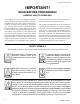
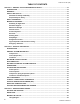
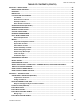
Table Of Contents
- Form 150.72-NM1 (908)
- GENERAL SAFETY GUIDELINES
- CHANGEABILITY OF THIS DOCUMENT
- TABLE OF CONTENTS
- LIST OF FIGURES
- LIST OF TABLES
- SECTION 1 – GENERAL CHILLER INFORMATION & SAFETY
- SECTION 2 – PRODUCT DESCRIPTION
- INTRODUCTION
- GENERAL SYSTEM DESCRIPTION
- HIGH AMBIENT KIT
- BUILDING AUTOMATION SYSTEM INTERFACE
- MILLENIUM CONTROL CENTER
- POWER PANEL
- ACCESSORIES AND OPTIONS
- UNIT COMPONENTS
- CONTROL / POWER PANEL COMPONENTS
- PRODUCT IDENTIFICATION NUMBER (PIN)
- BASIC UNIT NOMENCLATURE
- REFRIGERANT FLOW DIAGRAM
- PROCESS AND INSTRUMENTATION DIAGRAM
- SECTION 3 – HANDLING AND STORAGE
- SECTION 4 – INSTALLATION
- INSTALLATION CHECKLIST
- HANDLING
- INSPECTION
- LOCATION AND CLEARANCES
- SPRING ISOLATORS (OPTIONAL)
- COMPRESSOR MOUNTING
- REMOTE COOLER OPTION
- CHILLED LIQUID PIPING
- PIPEWORK ARRANGEMENT
- DUCT WORK CONNECTION
- WIRING
- COMPRESSOR HEATERS
- RELIEF VALVES
- HIGH PRESSURE CUTOUT
- SINGLE-POINT SUPPLY CONNECTION – TERMINAL BLOCK, NON-FUSED DISCONNECT SWITCH OR CIRCUIT BREAKER
- USER CONTROL WIRING INPUTS
- USER CONTROL WIRING OUTPUTS
- SECTION 5 – TECHNICAL DATA
- OPERATIONAL LIMITATIONS (ENGLISH)
- HEAT EXCHANGER FLOW, GPM
- PHYSICAL DATA (ENGLISH)
- ELECTRICAL DATA
- ELECTRICAL NOTES
- ELECTRICAL DATA W/O PUMPS
- ELECTRICAL DATA W/ PUMPS
- ELECTRICAL NOTES AND LEGEND
- WIRING DIAGRAMS
- DIMENSIONS (ENGLISH)
- TECHNICAL DATA – CLEARANCES
- WEIGHT DISTRIBUTION AND ISOLATOR MOUNTING POSITIONS
- ISOLATOR INFORMATION FOR UNITS SHIPPED ON OR AFTER JUNE 15, 2008
- ISOLATOR INFORMATION FOR UNITS SHIPPED BEFORE JUNE 15, 2008
- SLRS Seismic Isolator Specifications
- SLRS Seismic Isolator Installation and Adjustment
- One Inch Deflection Spring Isolator Cross-reference
- Installation of 1” Deflection Mounts
- Neoprene Isolator Cross-reference
- Two Inch Deflection, Seismic Spring IsolatorCross-reference - SLRS
- SLRS Seismic Isolator Installation and Adjustment
- SECTION 6 – COMMISSIONING
- SECTION 7 – UNIT CONTROLS
- SECTION 8 – UNIT OPERATION
- CAPACITY CONTROL
- SUCTION PRESSURE LIMIT CONTROLS
- DISCHARGE PRESSURE LIMIT CONTROLS
- LEAVING CHILLED LIQUID CONTROL
- LEAVING CHILLED LIQUID CONTROLOVERRIDE TO REDUCE CYCLING
- LEAVING CHILLED LIQUID SYSTEM LEAD/LAG AND COMPRESSOR SEQUENCING
- RETURN CHILLED LIQUID CONTROL
- RETURN CHILLLED LIQUID SYSTEM LEAD/LAG AND COMPRESSOR SEQUENCING
- ANTI-RECYCLE TIMER
- ANTI-COINCIDENCE TIMER
- EVAPORATOR PUMP CONTROL & YORK HYDRO KIT PUMP CONTROL
- EVAPORATOR HEATER CONTROL
- PUMPDOWN CONTROL
- STANDARD CONDENSER FAN CONTROL
- LOAD LIMITING
- COMPRESSOR RUN STATUS
- ALARM STATUS
- REMOTE BAS/EMS TEMPERATURE RESET USINGA VOLTAGE OR CURRENT SIGNAL
- SECTION 9 – SERVICE AND TROUBLESHOOTING
- SECTION 10 – MAINTENANCE

JOHNSON CONTROLS
2
FORM 150.72-NM1 (908)
This equipment is a relatively complicated apparatus.
During installation, operation, maintenance or service,
individuals may be exposed to certain components or
conditions including, but not limited to: refrigerants,
oils, materials under pressure, rotating components,
and both high and low voltage. Each of these items
has the potential, if misused or handled improperly, to
cause bodily injury or death. It is the obligation and
responsibility of operating/service personnel to identify
and recognize these inherent hazards, protect themselves,
and proceed safely in completing their tasks. Failure to
comply with any of these requirements could result in
serious damage to the equipment and the property in
IMPORTANT!
READ BEFORE PROCEEDING!
GENERAL SAFETY GUIDELINES
which it is situated, as well as severe personal injury or
death to themselves and people at the site.
This document is intended for use by owner-authorized
operating/service personnel. It is expected that this
individual possesses independent training that will
enable them to perform their assigned tasks properly
and safely. It is essential that, prior to performing any
task on this equipment, this individual shall have read
and understood this document and any referenced
materials. This individual shall also be familiar with and
comply with all applicable governmental standards and
regulations pertaining to the task in question.
SAFETY SYMBOLS
The following symbols are used in this document to alert the reader to areas of potential hazard:
-
not
notno-