
Installation manual

292306-UIM-A-0108
20 Unitary Products Group
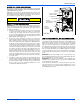
VENT SYSTEM
This furnace is certified to be installed with one of two possible vent
configurations.
1. Horizontal vent system. This vent system can be installed com-
pletely horizontal or combinations of horizontal, vertical, or offset
using elbows.
2. Vertical vent system. This vent system can be installed completely
vertical or a combination of horizontal, vertical, or offset using
elbows.
HORIZONTAL VENT APPLICATIONS AND
TERMINATION
When selecting the location for a horizontal combustion air / vent termi-
nation, the following should be considered:
1. Observe all clearances listed in vent clearances in these instruc-
tions.
2. Termination should be positioned where vent vapors will not dam-
age plants or shrubs or air conditioning equipment.
3. Termination should be located where it will not be affected by wind
gusts, light snow, airborne leaves or allow recirculation of flue
gases.
4. Termination should be located where it will not be damaged or
exposed to flying stones, balls, etc.
5. Termination should be positioned where vent vapors are not objec-
tionable.
6. Horizontal portions of the vent system must slope upwards and be
supported to prevent sagging. The vent system may be supported
by the use of clamps or hangers secured to a permanent part of
the structure every 4 ft. (1.22 m).
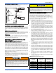
7. Sealed combustion air systems must be installed so the vent and
the combustion air pipes terminate in the same atmospheric zone.
Refer to Figures 22-24.
DOWNFLOW VENT ASSEMBLY
1. Place the 2” (5.08 cm) 45° PVC street elbow on the vent connec-
tion shown in Figure 20.
2. Place the 2” (5.08 cm) PVC WYE (“Y”) assembly on the 2” (5.08
cm) 45° PVC street elbow as shown in Figure 20.
3. Locate the rubber condensate hose in front of the blower access
panel.
4. Slide the hose through the hole in the top cover, and insert the
hose on to the barbed fitting on the bottom of the 2” (5.08 cm) PVC
WYE (“Y”) assembly as shown in Figure 20.
HORIZONTAL VENT ASSEMBLY
Horizontal Left Vent Assembly
1. Place the 2” (5.08 cm) 45° PVC street elbow on the vent connec-
tion shown in Figure 20.
2. Place the 2” (5.08 cm) PVC WYE (“Y”) assembly on the 2” (5.08
cm) 45° PVC street elbow as shown in Figure 20.
3. Refer to the “DOWNFLOW/HORIZONTAL CONDENSATE INTER-
NAL DRAIN CONFIGURATIONS” for further details.
Horizontal Right Vent Assembly
1. Place the 2” (5.08 cm) 45° PVC street elbow on the vent connec-
tion shown in Figure 20.
2. Place the 2” (5.08 cm) PVC WYE (“Y”) assembly on the 2” (5.08
cm) 45° PVC street elbow as shown in Figure 20.
3. Refer to the “DOWNFLOW/HORIZONTAL CONDENSATE INTER-
NAL DRAIN CONFIGURATIONS” for further details.
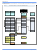
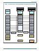
FIGURE 20: Downflow/Horizontal Vent Assembly
HORIZONTAL RIGHT
HORIZONTAL LEFT
DOWNFLOW
2” (5.08 cm)
VENT PIPE
2” PVC
WYE
2” PVC
45°
STELL
FURNACE
VENT PIPE
BARBED
FITTING
RETURN
AIR
RETURN
AIR
RETURN
AIR
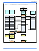
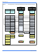
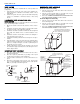
FIGURE 21: Termination Configuration - 1 Pipe
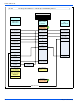
FIGURE 22: Termination Configuration - 2 Pipe
12” MIN.
12” MIN.
MAINTAIN 12” MINIMUM CLEARANCE
ABOVE HIGHEST ANTICIPATED SNOW
LEVEL. MAXIMUM 24” ABOVE ROOF.
MAINTAIN 12”
MINIMUM
CLEARANCE
ABOVE HIGHEST
ANTICIPATED
SNOW LEVEL.
12” VERTICAL SEPARATION
BETWEEN COMBUSTION AIR
AND VENT
12” MINIMUM
BELOW
OVERHANG
12” SEPARATION
BETWEEN BOTTOM
OF COMBUSTION
AIR PIPE AND
BOTTOM OF VENT
MAINTAIN 12”
MINIMUM CLEARANCE
ABOVE HIGHEST
ANTICIPATED SNOW
LEVEL OR GRADE,
WHICHEVER IS
HIGHER