528194-YTG-P-1014 ® TECHNICAL GUIDE R-410A ZF SERIES 6.5 - 12.5 TON 60 Hertz Description ASHRAE 90.1 COMPLIANT YORK® Predator® units are convertible single packages with a common footprint cabinet and common roof curb for all 6.5 through 12.5 ton models. All units have two compressors with independent refrigeration circuits to provide 2 stages of cooling. The units were designed for light commercial applications and can be easily installed on a roof curb, slab, or frame.
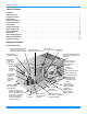
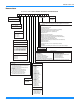
528194-YTG-P-1014 Table of Contents Description . . . . . . . . . . . . . . . . . . . . . . . . . . . . . . . . . . . . . . . . . . . . . . . . . . . . . . . . . . . . . . . . . . . . . . . . . . . . . . . . . . . . . . . . . . . . 1 Table of Contents . . . . . . . . . . . . . . . . . . . . . . . . . . . . . . . . . . . . . . . . . . . . . . . . . . . . . . . . . . . . . . . . . . . . . . . . . . . . . . . . . . . . . . . 2 Component Location . . . . . . . . . . . . . . . . . . . . . . . . . . . . . . . .
528194-YTG-P-1014 Nomenclature 6.5-12.5 Ton York® Model Number Nomenclature Z F 090 N10 A 2 A AA 7 0 1 2 4 A Product Style Product Category A = Style A B = Style B C = Style C Z = A/C, Single Pkg., R-410A Configuration Options (not required for all units) These four digits will not be assigned until a quote is requested, or an order placed. Product Identifier SS Drain Pan CPC Controller, DFS, APS F = 11.
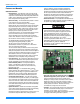
528194-YTG-P-1014 Features and Benefits Standard Features • High Efficiency – High efficiency units reach as high as 11.2 EER. Gas/electric units have electronic spark ignition and power vented combustion with steady state efficiencies of 80%. These efficiencies exceed all legislated minimum levels and provide low operating costs. • Service Friendly - The Predator® incorporates a number of key features for ease of serviceability. Service time is reduced through the use of hinged, toolless panels.
28194-YTG-P-1014 • Reduce field installed complexity - Each unit will comes equipped with factory installed supply air, return air, and outdoor air temperature sensors providing key temperature readings thus reduce field installed complexity. • On-board USB Port - The new control comes with a long list of features including data logging, current and previous system faults and software update capabilities using the on board USB port and common flash drive.
528194-YTG-P-1014 installer needs only to assemble the outdoor air hood, attach the enthalpy control the hood and mount the hood to the unit (Hood and control are provided). • Power Exhaust - This factory option allows down flow or horizontal end return economizer operation. The power exhaust must be removed from the unit and mounted in the horizontal end return duct work when applying the product in the horizontal, end return configuration.
528194-YTG-P-1014 • Technicoat Condenser Coils - The condenser coils are coated with a phenolic coating for protection against corrosion due to harsh environments. • Technicoat Evaporator Coil - The evaporator coils are coated with a phenolic coating for protection against corrosion due to harsh environments. • E-coat Condenser Coils - The condenser coils are coated with an epoxy polymer coating to protect against corrosion.
528194-YTG-P-1014 • • • • 8 valve and controls will continue to function properly at extremely low temperatures. Gas Heat High Altitude Kit - This kit converts a gas heat unit to operate at high altitudes, 2,000 to 6,000 feet. Conversion kits are available for natural gas and propane. Gas Heat Propane Conversion Kit - This kit converts a gas-fired heater from natural gas to propane. It contains the main burner orifices and gas valve replacement springs.
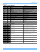
528194-YTG-P-1014 Accessories Field Installed Accessories - Non-Electrical MODEL 1BD0408 1CG0419 1CG0420 1CG0427 1CG0428 VOLTAGE All All All All All 1HG0411 1HG0415 1FE0411 1FF0414 1FF0415 1FL0402 1FL0423 1GP0405 1HA0442 1HA0443 1NP0442 1RC0470 1RC0471 All All All All All All All All All All All All All 1RC0472 All 1WC0412 All DESCRIPTION Burglar Bars, Downflow Coil Guard Coil Guard Coil Guard Coil Guard Hail Guard Kit Hail Guard Kit Flue Exhaust Extension Kit 2" only Metal Filter Frame Kit 2" only
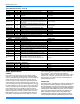
528194-YTG-P-1014 Accessories (Continued) Field Installed Accessories - Fresh Air MODEL 1FA0413 1FA0414 1EH0408 2EC0401 2EC0402 2EE04707624 2EE04707424 2EE04706924 2MD04703824 2MD04703924 2PE04704706* 2PE04704746* 2PE04704758* VOLTAGE DESCRIPTION All Manual Outside Air Damper 0-35%, Downflow All Manual Outside Air Damper 0-100%, Downflow Barometric Relief Kit for Power Exhaust, Horizontal All Application All Single Enthalpy Control All Dual Enthalpy Control (Includes 2 Sensors) Economizer for Downflow, E
528194-YTG-P-1014 shall be CSA certified to ANSI Z21.47 and UL 1995/CAN/CSA No. 236-M90 standards. UNIT CABINET Unit cabinet shall be constructed of galvanized steel with exterior surfaces coated with a non-chalking, powder paint finish, certified at 1000 hour salt spray test per ASTM-B117 standards. Indoor blower sections shall be insulated with up to 1” thick insulation coated on the airside.
528194-YTG-P-1014 bustion with post purge logic, energy saving direct spark ignition, and redundant main gas valve. The heat exchanger shall be of the tubular type, constructed of T1-40 aluminized steel for corrosion resistance and allowing minimum mixed air entering temperature of 40 ºF. Burners shall be of the in-shot type, constructed of aluminum-coated steel. All gas piping shall enter the unit cabinet at a single location, through either the side or bottom, without any field modifications.
528194-YTG-P-1014 • BREAKER – An HACR breaker can be factory installed on gas heat units or cooling units with electric heat. • DISCONNECT SWITCH - A disconnect can be factory installed on a cooling only units sized for the largest electric heat available. • STAINLESS STEEL HEAT EXCHANGER – For applications in a corrosive environment, this option provides a full stainless steel heat exchanger assembly.
528194-YTG-P-1014 Physical Data ZF078-150 Physical Data Models Component ZF078 ZF090 ZF102 ZF120 ZF150 6.5 7.5 8.5 10 12.5 Gross Capacity @ AHRI A point (Mbh) 81000 90000 104000 126000 156000 AHRI net capacity (Mbh) 78000 88000 100000 120000 150000 EER 11.2 11.2 11.2 11.2 11.0 IEER 12.51/12.32 12.51/12.32 12.51/12.32 12.31/12.12 12.31/12.12 IPLV 12.9 12.1 12.5 12.6 13.06 CFM 2500 2500 3400 4000 4050 System power (KW) 6.95 7.87 8.90 10.70 13.
528194-YTG-P-1014 ZF078-150 Physical Data (Continued) Models Component ZF078 ZF090 ZF102 ZF120 ZF150 6.5 7.5 8.5 10 12.5 2 2 2 2 4 Nominal Tonnage CONDENSER FAN DATA Quantity of Fans Fan diameter (Inch) 24 24 24 24 24 Type Prop Prop Prop Prop Prop Drive type Direct Direct Direct Direct Direct 2 2 2 2 4 1/3 3/4 3/4 3/4 3/4 Quantity of motors Motor HP each No.
528194-YTG-P-1014 ZF078-150 Unit Limitations Unit Limitations Size (Tons) 078 (6.5) 090 (7.5) 102 (8.5) 120 (10) 150 (12.
528194-YTG-P-1014 Capacity Performance ZF078-150 Cooling Capacities ZF078 (6.5 Ton) Air on Evaporator Coil CFM 1625 1950 2275 2600 2925 3250 1625 1950 2275 2600 2925 3250 WB (°F) Total Capacity1 (MBh) Total Input (kW)2 77 72 67 62 77 72 67 62 57 77 72 67 62 57 77 72 67 62 57 72 67 62 57 72 67 62 57 102.9 94.8 86.7 79.2 106.6 98.2 89.8 82.0 79.2 110.2 101.6 92.9 84.8 81.9 113.9 104.9 95.9 87.6 84.6 107.2 98.0 89.5 86.5 109.4 100.1 91.4 88.3 5.0 5.0 5.0 5.0 5.0 5.0 5.0 5.0 4.9 5.0 5.0 5.
528194-YTG-P-1014 ZF078 (6.5 Ton) (Continued) Air on Evaporator Coil CFM 1625 1950 2275 2600 2925 3250 WB (°F) Total Capacity1 (MBh) Total Input (kW)2 90 77 72 67 62 77 72 67 62 57 77 72 67 62 57 77 72 67 62 57 72 67 62 57 72 67 62 57 75.2 67.9 60.5 56.1 77.6 70.0 62.4 57.8 53.2 80.0 72.2 64.3 59.6 54.8 82.3 74.3 66.2 61.4 56.5 75.5 67.3 62.4 57.4 76.8 68.4 63.4 58.4 7.3 7.1 7.0 6.8 7.3 7.2 7.0 6.9 6.8 7.4 7.2 7.0 6.9 6.8 7.4 7.2 7.1 7.0 6.9 7.3 7.1 7.0 6.9 7.3 7.1 7.0 6.9 29.2 43.8 58.4 56.
528194-YTG-P-1014 ZF090 (7.5 Ton) Air on Evaporator Coil CFM 1875 2250 2625 3000 3375 3750 1875 2250 2625 3000 3375 3750 WB (°F) Total Capacity1 (MBh) Total Input (kW)2 90 77 72 67 62 77 72 67 62 57 77 72 67 62 57 77 72 67 62 57 72 67 62 57 72 67 62 57 119.9 110.5 101.1 91.2 123.0 113.3 103.6 93.6 95.1 126.0 116.1 106.2 95.9 97.4 129.1 118.9 108.8 98.2 99.8 122.5 112.0 101.1 102.8 126.1 115.3 104.1 105.8 6.0 6.0 6.0 6.1 6.0 6.0 6.1 6.1 6.0 6.1 6.1 6.1 6.1 6.0 6.1 6.1 6.1 6.1 6.1 6.1 6.
528194-YTG-P-1014 ZF090 (7.5 Ton) (Continued) Air on Evaporator Coil CFM 1875 2250 2625 3000 3375 3750 WB (°F) Total Capacity1 (MBh) Total Input (kW)2 90 77 72 67 62 77 72 67 62 57 77 72 67 62 57 77 72 67 62 57 72 67 62 57 72 67 62 57 87.3 79.0 70.7 64.2 89.5 81.0 72.5 65.8 68.5 91.6 82.9 74.3 67.4 70.1 93.8 84.9 76.0 68.9 71.8 86.6 77.6 70.3 73.2 88.3 79.1 71.7 74.7 8.6 8.4 8.1 8.0 8.6 8.4 8.2 8.1 8.0 8.7 8.5 8.3 8.1 8.1 8.7 8.5 8.3 8.2 8.2 8.6 8.4 8.2 8.2 8.6 8.4 8.2 8.2 35.4 50.6 65.8 64.
528194-YTG-P-1014 ZF102 (8.5 Ton) Air on Evaporator Coil CFM 2125 2550 2975 3400 3825 4250 2125 2550 2975 3400 3825 4250 WB (°F) Total Capacity1 (MBh) Total Input (kW)2 90 77 72 67 62 77 72 67 62 57 77 72 67 62 57 77 72 67 62 57 72 67 62 57 72 67 62 57 134.7 123.6 112.5 101.7 139.2 127.8 116.3 105.1 102.6 143.8 131.9 120.1 108.6 106.0 148.4 136.1 123.9 112.0 109.4 138.3 125.8 113.8 111.1 140.4 127.8 115.5 112.8 6.6 6.6 6.5 6.5 6.5 6.5 6.5 6.5 6.5 6.5 6.5 6.5 6.5 6.5 6.5 6.5 6.5 6.5 6.
528194-YTG-P-1014 ZF102 (8.5 Ton) (Continued) Air on Evaporator Coil CFM 2125 2550 2975 3400 3825 4250 WB (°F) Total Capacity1 (MBh) Total Input (kW)2 90 77 72 67 62 77 72 67 62 57 77 72 67 62 57 77 72 67 62 57 72 67 62 57 72 67 62 57 103.0 92.4 81.7 78.2 103.6 92.9 82.1 78.6 79.5 104.2 93.4 82.6 79.1 80.0 104.8 93.9 83.1 79.5 80.4 96.1 85.0 81.4 82.3 98.3 87.0 83.2 84.2 9.4 9.1 8.9 8.8 9.4 9.2 8.9 8.8 8.9 9.5 9.2 9.0 8.9 8.9 9.5 9.3 9.0 8.9 9.0 9.3 9.1 8.9 9.0 9.3 9.1 9.0 9.0 37.0 57.6 78.
528194-YTG-P-1014 ZF120 (10 Ton) Air on Evaporator Coil CFM 2500 3000 3500 4000 4500 5000 2500 3000 3500 4000 4500 5000 WB (°F) Total Capacity1 (MBh) Total Input (kW)2 90 77 72 67 62 77 72 67 62 57 77 72 67 62 57 77 72 67 62 57 72 67 62 57 72 67 62 57 165.2 149.2 133.2 121.8 170.9 154.3 137.7 125.9 120.2 176.6 159.4 142.3 130.1 124.2 182.2 164.5 146.8 134.3 128.2 168.0 149.9 137.1 130.9 171.4 153.0 139.9 133.5 7.4 7.5 7.5 7.5 7.4 7.4 7.4 7.5 7.4 7.4 7.4 7.4 7.5 7.4 7.3 7.4 7.4 7.4 7.4 7.
528194-YTG-P-1014 ZF120 (10 Ton) (Continued) Air on Evaporator Coil CFM 2500 3000 3500 4000 4500 5000 WB (°F) Total Capacity1 (MBh) Total Input (kW)2 90 77 72 67 62 77 72 67 62 57 77 72 67 62 57 77 72 67 62 57 72 67 62 57 72 67 62 57 117.2 106.1 95.0 85.5 120.1 108.7 97.4 87.5 90.8 122.9 111.3 99.7 89.6 93.0 125.8 113.9 102.0 91.7 95.1 115.9 103.8 93.3 96.8 117.9 105.6 95.0 98.5 11.2 10.8 10.4 10.1 11.2 10.9 10.5 10.2 10.3 11.3 10.9 10.6 10.3 10.4 11.4 11.0 10.6 10.4 10.5 11.1 10.7 10.4 10.
528194-YTG-P-1014 ZF150 (12.5 Ton) Air on Evaporator Coil CFM 3125 3750 4375 5000 5625 6250 3125 3750 4375 5000 5625 6250 WB (°F) Total Capacity1 (MBh) Total Input (kW)2 90 77 72 67 62 77 72 67 62 57 77 72 67 62 57 77 72 67 62 57 72 67 62 57 72 67 62 57 192.8 179.7 166.6 150.6 200.7 187.1 173.4 156.8 152.3 208.7 194.5 180.2 163.0 158.3 216.6 201.8 187.1 169.2 164.3 203.6 188.7 170.7 165.7 205.4 190.4 172.2 167.2 10.1 9.8 9.6 9.5 10.1 9.9 9.6 9.5 9.5 10.1 9.9 9.7 9.6 9.5 10.1 9.9 9.7 9.
528194-YTG-P-1014 ZF150 (12.5 Ton) (Continued) Air on Evaporator Coil CFM 3125 3750 4375 5000 5625 6250 WB (°F) Total Capacity1 (MBh) Total Input (kW)2 90 77 72 67 62 77 72 67 62 57 77 72 67 62 57 77 72 67 62 57 72 67 62 57 72 67 62 57 152.8 139.4 125.9 117.0 158.0 144.1 130.1 121.0 119.1 163.2 148.8 134.4 125.0 123.0 168.3 153.5 138.7 128.9 126.9 156.2 141.1 131.2 129.2 158.9 143.6 133.5 131.4 14.9 14.8 14.7 14.5 14.9 14.8 14.7 14.5 14.6 14.9 14.8 14.7 14.6 14.6 15.0 14.9 14.8 14.6 14.6 14.
528194-YTG-P-1014 Airflow Performance ZF078-150 Side Duct Application ZF078 (6.5 Ton) Side Duct Air Flow (CFM) 1800 2000 2200 2400 2600 2800 3000 3200 3400 Available External Static Pressure - IWG1 0.2 0.4 0.6 0.8 1.0 1.2 1.4 1.6 1.8 2.0 RPM BHP RPM BHP RPM BHP RPM BHP RPM BHP RPM BHP RPM BHP RPM BHP RPM BHP RPM BHP 751 776 804 835 869 906 945 987 1030 Field Supplied Drive 0.22 813 0.43 872 0.35 838 0.56 897 0.50 866 0.71 925 0.66 897 0.87 956 0.84 931 1.05 990 1.03 968 1.25 1027 1.25 1007 1.46 1066 1.
528194-YTG-P-1014 ZF120 (10 Ton) Side Duct Air Flow (CFM) 2600 2800 3000 3200 3400 3600 3800 4000 4200 4400 4600 4800 5000 Available External Static Pressure - IWG1 0.2 0.4 0.6 0.8 1.0 1.2 1.4 1.6 1.8 2.0 RPM BHP RPM BHP RPM BHP RPM BHP RPM BHP RPM BHP RPM BHP RPM BHP RPM BHP RPM BHP Field Supplied Drive 675 0.53 726 0.74 686 0.63 738 0.84 699 0.75 750 0.96 713 0.88 764 1.09 728 1.02 779 1.23 745 1.18 796 1.39 763 1.36 815 1.57 783 1.55 835 1.76 805 1.77 856 1.98 828 2.00 879 2.21 852 2.25 904 2.46 879 2.
528194-YTG-P-1014 ZF078-150 Bottom Duct Application ZF078 (6.5 Ton) Bottom Duct Air Flow (CFM) 1800 2000 2200 2400 2600 2800 3000 3200 3400 Available External Static Pressure - IWG1 0.2 0.4 0.6 0.8 1.0 1.2 1.4 1.6 1.8 2.0 RPM BHP RPM BHP RPM BHP RPM BHP RPM BHP RPM BHP RPM BHP RPM BHP RPM BHP RPM BHP Field Supplied Drive 775 0.31 850 0.53 803 0.45 878 0.67 838 0.60 913 0.82 878 0.78 953 1.00 923 0.98 997 1.20 971 1.20 1046 1.42 1023 1.44 1097 1.66 1077 1.71 1151 1.93 1133 1.99 1208 2.
528194-YTG-P-1014 ZF120 (10 Ton) Bottom Duct Air Flow (CFM) 2600 2800 3000 3200 3400 3600 3800 4000 4200 4400 4600 Available External Static Pressure - IWG1 0.2 0.4 0.6 0.8 1.0 1.2 1.4 1.6 1.8 2.0 RPM BHP RPM BHP RPM BHP RPM BHP RPM BHP RPM BHP RPM BHP RPM BHP RPM BHP RPM BHP Field Supplied Drive 722 0.83 744 0.97 769 1.13 797 1.32 828 1.52 861 1.75 897 2.00 935 2.27 976 2.57 1019 2.88 1065 3.22 Standard 2 HP & Drive 776 798 823 851 882 915 951 989 1030 1073 1119 0.97 1.12 1.28 1.46 1.67 1.90 2.15 2.
528194-YTG-P-1014 RPM Selection Size (Tons) 078 (6.5) Model ZF 090 (7.5) ZF 102 (8.5) ZF 120 (10) ZF 150 (12.5) ZF HP 1.5 2 1.5 3 2 3 2 3 3 5 Max BHP 1.73 2.30 1.73 3.45 2.30 3.45 2.30 3.45 3.45 5.
528194-YTG-P-1014 Drive Selection 1. Determine side or bottom supply duct Application. 2. Determine desired airflow. 3. Calculate or measure the amount of external static pressure. 4. Using the operating point determined from steps 1, 2 & 3, locate this point on the appropriate supply air blower performance table. (Linear interpolation may be necessary.) 5. Noting the RPM and BHP from step 4, locate the appropriate motor and, or drive on the RPM selection table. 6.
528194-YTG-P-1014 Altitude/Temperature Correction Factors Air Temp. 40 50 60 70 80 90 100 0 1.060 1.039 1.019 1.000 0.982 0.964 0.946 1000 1.022 1.002 0.982 0.964 0.947 0.929 0.912 2000 0.986 0.966 0.948 0.930 0.913 0.897 0.880 3000 0.950 0.931 0.913 0.896 0.880 0.864 0.848 4000 0.916 0.898 0.880 0.864 0.848 0.833 0.817 Altitude (Ft.) 5000 0.882 0.864 0.848 0.832 0.817 0.802 0.787 6000 0.849 0.832 0.816 0.801 0.787 0.772 0.758 7000 0.818 0.802 0.787 0.772 0.758 0.744 0.730 8000 0.788 0.772 0.
528194-YTG-P-1014 Gas Heat Minimum Supply Air Supply Air (CFM) Size (Tons) Model 078 (6.5) 090 (7.5) 102 (8.5) 120 (10) 150 (12.
528194-YTG-P-1014 Electric Heat Multipliers Voltage Nominal kW Capacity Multipliers1 Applied 208 230 460 575 240 480 600 0.75 0.92 0.92 0.92 1. Electric heaters are rated at nominal voltage. Use this table to determine the electric heat capacity for heaters applied at lower voltages. Sound Performance Indoor Sound Power Levels Size (Tons) 078 (6.5) 090 (7.5) 102 (8.5) 120 (10) 150 (12.
528194-YTG-P-1014 Electrical Data ZF078-150 Standard Motor - Without Powered Convenience Outlet Size (Tons) Volt Compressors (each) RLA LRA MCC OD Fan Motors (each) Supply Blower Motor Pwr Exh Motor Pwr Conv Outlet FLA FLA FLA FLA 208 9.8 68.0 14.5 2.1 5.2 5.5 0.0 230 9.8 68.0 14.5 2.1 5.2 5.5 0.0 460 4.9 34.0 7.7 1.3 2.6 2.2 0.0 575 3.8 28.0 6.0 0.7 2.0 1.8 0.0 208 11.9 88.0 18.5 3.0 5.2 5.5 0.0 230 11.9 88.0 18.5 3.0 5.2 5.5 0.0 460 5.2 44.
528194-YTG-P-1014 ZF078-150 Standard Motor - Without Powered Convenience Outlet (Continued) Size (Tons) Volt Compressors (each) RLA LRA MCC OD Fan Motors (each) Supply Blower Motor Pwr Exh Motor Pwr Conv Outlet FLA FLA FLA FLA 208 14.6 110.0 21.7 3.0 6.8 5.5 0.0 230 14.6 110.0 21.7 3.0 6.8 5.5 0.0 460 7.4 55.0 11.5 1.6 3.4 2.2 0.0 575 5.6 43.0 8.7 1.4 2.4 1.8 0.0 208 23.1 160.0 36.0 3.0 9.6 5.5 0.0 230 23.1 160.0 36.0 3.0 9.6 5.5 0.0 460 12.2 87.0 19.
528194-YTG-P-1014 ZF078-150 Hi Static Motor - Without Powered Convenience Outlet Size (Tons) Volt Compressors (each) RLA LRA MCC OD Fan Motors (each) Supply Blower Motor Pwr Exh Motor Pwr Conv Outlet FLA FLA FLA FLA 208 9.8 68.0 14.5 2.1 6.8 5.5 0.0 230 9.8 68.0 14.5 2.1 6.8 5.5 0.0 460 4.9 34.0 7.7 1.3 3.4 2.2 0.0 575 3.8 28.0 6.0 0.7 2.4 1.8 0.0 208 11.9 88.0 18.5 3.0 9.6 5.5 0.0 230 11.9 88.0 18.5 3.0 9.6 5.5 0.0 460 5.2 44.0 8.1 1.6 4.
528194-YTG-P-1014 ZF078-150 Hi Static Motor - Without Powered Convenience Outlet (Continued) Size (Tons) Volt Compressors (each) RLA LRA MCC OD Fan Motors (each) Supply Blower Motor Pwr Exh Motor Pwr Conv Outlet FLA FLA FLA FLA 208 14.6 110.0 21.7 3.0 9.6 5.5 0.0 230 14.6 110.0 21.7 3.0 9.6 5.5 0.0 460 7.4 55.0 11.5 1.6 4.7 2.2 0.0 575 5.6 43.0 8.7 1.4 3.6 1.8 0.0 208 23.1 160.0 36.0 3.0 14.0 5.5 0.0 230 23.1 160.0 36.0 3.0 14.0 5.5 0.0 460 12.2 87.
528194-YTG-P-1014 ZF078-150 Standard Motor - With Powered Convenience Outlet Size (Tons) Volt Compressors (each) RLA LRA MCC OD Fan Motors (each) Supply Blower Motor Pwr Exh Motor Pwr Conv Outlet FLA FLA FLA FLA 208 9.8 68.0 14.5 2.1 5.2 5.5 10.0 230 9.8 68.0 14.5 2.1 5.2 5.5 10.0 460 4.9 34.0 7.7 1.3 2.6 2.2 5.0 575 3.8 28.0 6.0 0.7 2.0 1.8 4.0 208 11.9 88.0 18.5 3.0 5.2 5.5 10.0 230 11.9 88.0 18.5 3.0 5.2 5.5 10.0 460 5.2 44.0 8.1 1.6 2.
528194-YTG-P-1014 ZF078-150 Standard Motor - With Powered Convenience Outlet (Continued) Size (Tons) Volt Compressors (each) RLA LRA MCC OD Fan Motors (each) Supply Blower Motor Pwr Exh Motor Pwr Conv Outlet FLA FLA FLA FLA 208 14.6 110.0 21.7 3.0 6.8 5.5 10.0 230 14.6 110.0 21.7 3.0 6.8 5.5 10.0 460 7.4 55.0 11.5 1.6 3.4 2.2 5.0 575 5.6 43.0 8.7 1.4 2.4 1.8 4.0 208 23.1 160.0 36.0 3.0 9.6 5.5 10.0 230 23.1 160.0 36.0 3.0 9.6 5.5 10.0 460 12.2 87.0 19.
528194-YTG-P-1014 ZF078-150 Hi Static Motor - With Powered Convenience Outlet Size (Tons) Volt Compressors (each) RLA LRA MCC OD Fan Motors (each) Supply Blower Motor Pwr Exh Motor Pwr Conv Outlet FLA FLA FLA FLA 208 9.8 68.0 14.5 2.1 6.8 5.5 10.0 230 9.8 68.0 14.5 2.1 6.8 5.5 10.0 460 4.9 34.0 7.7 1.3 3.4 2.2 5.0 575 3.8 28.0 6.0 0.7 2.4 1.8 4.0 208 11.9 88.0 18.5 3.0 9.6 5.5 10.0 230 11.9 88.0 18.5 3.0 9.6 5.5 10.0 460 5.2 44.0 8.1 1.6 4.
528194-YTG-P-1014 ZF078-150 Hi Static Motor - With Powered Convenience Outlet (Continued) Size (Tons) Volt Compressors (each) RLA LRA MCC OD Fan Motors (each) Supply Blower Motor Pwr Exh Motor Pwr Conv Outlet FLA FLA FLA FLA 208 14.6 110.0 21.7 3.0 9.6 5.5 10.0 230 14.6 110.0 21.7 3.0 9.6 5.5 10.0 460 7.4 55.0 11.5 1.6 4.7 2.2 5.0 575 5.6 43.0 8.7 1.4 3.6 1.8 4.0 208 23.1 160.0 36.0 3.0 14.0 5.5 10.0 230 23.1 160.0 36.0 3.0 14.0 5.5 10.0 460 12.2 87.
528194-YTG-P-1014 Typical Wiring Diagrams ZF078-150 Typical Wiring Diagrams Typical ZF078-120 Cooling Unit with Gas Heat 208/230 Volt Wiring Diagram 44 Johnson Controls Unitary Products
528194-YTG-P-1014 Typical ZF078-120 Cooling Unit with Gas Heat 208/230 Volt Unit (Options) Johnson Controls Unitary Products 45
528194-YTG-P-1014 Typical ZF078-120 Cooling Unit with Gas Heat 460/575 Volt Wiring Diagram 46 Johnson Controls Unitary Products
528194-YTG-P-1014 Typical ZF078-120 Cooling Unit with Gas Heat 460/575 Volt Unit (Options) Johnson Controls Unitary Products 47
528194-YTG-P-1014 Typical ZF078-120 Cooling Unit with/without Electric Heat Wiring Diagram 48 Johnson Controls Unitary Products
528194-YTG-P-1014 Typical ZF78-120 Cooling Unit with/without Electric Heat Unit (Options) Johnson Controls Unitary Products 49
528194-YTG-P-1014 Typical ZF150 Cooling Unit with Gas Heat 208/230 Volt Wiring Diagram 50 Johnson Controls Unitary Products
528194-YTG-P-1014 Typical ZF150 Cooling Unit with Gas Heat 208/230 Volt Unit (Options) Johnson Controls Unitary Products 51
8194-YTG-P-1014 Typical ZF150 Cooling Unit with Gas Heat 460/575 Volt Wiring Diagram 52 Johnson Controls Unitary Products
528194-YTG-P-1014 Typical ZF150 Cooling Unit with Gas Heat 460/575 Volt Unit (Options) Johnson Controls Unitary Products 53
528194-YTG-P-1014 Typical ZF150 Cooling Unit with/without Electric Heat Wiring Diagram 54 Johnson Controls Unitary Products
528194-YTG-P-1014 Typical ZF150 Cooling Unit with/without Electric Heat Unit (Options) Johnson Controls Unitary Products 55
528194-YTG-P-1014 BAS Controls Typical Wiring Diagrams Typical SURVEYOR BAS Control Wiring Diagram 56 Johnson Controls Unitary Products
528194-YTG-P-1014 Typical CPC BAS Control Wiring Diagram Johnson Controls Unitary Products 57
528194-YTG-P-1014 Typical HONEYWELL BAS Control Wiring Diagram 58 Johnson Controls Unitary Products
528194-YTG-P-1014 Typical HONEYWELL BAS Control Wiring Diagram Johnson Controls Unitary Products 59
528194-YTG-P-1014 Weights and Dimensions ZF078-150 Unit Weights Unit 4 Point Load Weight Unit 6 Point Load Weight FRONT FRONT LEFT LEFT B C B A A E F D Y X FRONT LEFT Weight (lbs.) Center of Gravity Size Model Shipping Operating X Y (Tons) 078 ZF 865 860 38 24 (6.5) 090 ZF 885 860 38 24 (7.5) 102 ZF 1012 1007 38 24 (8.5) 120 ZF 1065 1060 38 24 (10) 150 ZF 1258 1253 47 25 (12.5) 60 D C 4 Point Load Location (lbs.) A B C D A 6 Point Load Location (lbs.
528194-YTG-P-1014 ZF078-150 Unit Accessory Weights Unit Accessory Economizer Power Exhaust Electric Heat1 Gas Heat2 Variable Frequency Drive3 Weight (lbs.) Shipping Operating 90 85 40 35 49 49 110 110 30 30 1. Weight given is for the maximum heater size available (54KW). 2. Weight given is for the maximum number of tube heat exchangers available (8 tube). 3. Weight includes mounting hardware, controls and manual bypass option (ZF Only). ZF078-150 Unit Dimensions ZF078 - 120 29.69 15.25 15.38 59.
528194-YTG-P-1014 ZF150 45.64 14.92 4X Ø 24.38 14.92 58.09 14.92 29.95 30.11 B SEE DETAIL A FOR GAS INLET A C D E 11.38 F 59.00 SEE DETAIL B FOR DRAIN LOCATION 4.19 27.31 LEFT 21.19 89.00 FRONT ZF078-150 Unit Physical Dimensions Unit Model Number 078 090 102 120 150 62 A 42 42 50 3/4 50 3/4 50 3/4 B 89 89 89 89 119 1/2 Dimension (in.
528194-YTG-P-1014 Detail A 3.184 3.184 Gas Pipe Inlet Gas Pipe Inlet Ø 2.000 Ø 2.000 Gas Exhaust Vent Gas Exhaust Vent Ø 3.126 Ø 3.126 17.541 14.594 7.715 7.705 4.737 4.727 42” CABINET 50 3/4” CABINET Detail B 5-3/8 3/4” FPT ZF078-150 Unit Clearances Direction Top1 Front Rear Distance (in.) 72 36 36 Direction Right Left Bottom2 Distance (in.) 12 36 0 1. Units must be installed outdoors. Over hanging structure or shrubs should not obscure condenser air discharge outlet. 2.
528194-YTG-P-1014 ZF078-150 Unit Bottom Duct Openin 89 32 11/16 6 13/16 6 13/16 SUPPLY AIR RETURN AIR 27 1/2 LEFT 18 24 RIGHT 21 20 1/8 19 1/8 17 1/8 12 5/16 Bottom condensate drain 14 1/2 25 9/16 Bottom gas supply entry 16 3/8 18 1/16 FRONT TOP VIEW Bottom power, control and convenience outlet wiring entry 3X Ø 0.875 Ø 2.
528194-YTG-P-1014 ZF078-150 Unit Electrical Entry Disconnect Swith Cover Power Entry Ø 2-1/2 Control Entry Ø 7/8 Power Entry Ø 2-1/2 Convenience Outlet Cover Convenience Outlet Power Entry Ø 7/8 FRONT ZF078-120 Unit Side Duct Openings Dot Plugs 18-1/4 Return Air A Supply Air D B 2-31/32 5-5/32 C 31-11/16 Johnson Controls Unitary Products 65
528194-YTG-P-1014 ZF150 Unit Side Duct Openings Dot Plugs 18-1/4 A D B 5-5/32 2-7/8 C 31-5/8 ZF Side Duct Dimensions Unit Model Number 078 090 102 120 150 A 27 3/4 27 3/4 28 1/4 28 1/4 28 1/4 Dimension (in.
528194-YTG-P-1014 ZF078-150 Unit Accessory Dimensions ZF078-150 Roof Curb RIGHT 80-5/8 INSULATED DECK UNDER CONDENSER SECTION 20 SUPPLY 20 6 RETURN 2 TYP.
528194-YTG-P-1014 Economizer Options Economizer Usage Application Cabinet Height Description Model Side Return All Horizontal economizer without barometric relief 2EE047069241 Downflow, End Return Horizontal or ERV 42" Economizer, 42” tall cabinet 2EE047074242 50" Economizer, 50” tall cabinet 2EE047076242 1. Barometric relief must be ordered separately and installed in duct work. 2. Includes fresh air hood, exhaust hood and barometric relief.
Economizer End Return W/Power Exhaust Fresh Air Hood Field Installed Duct Work Low Leak Economizer Power Exhaust Barometric Relief Damper Barometric Relief Hood Field Installed Horizontal Economizer W/Power Exhaust Return Air Damper Field Installed Duct Work Fresh Air Damper Power Exhaust Barometric Relief Damper Barometric Relief Hood Subject to change without notice. Printed in U.S.A. Copyright © 2014 by Johnson Controls, Inc. All rights reserved.