528194-YTG-O-0614 ® TECHNICAL GUIDE R-410A ZF SERIES 6-1/2 - 12-1/2 TON 60 Hertz Description ASHRAE 90.1 COMPLIANT YORK® Predator® units are convertible single packages with a common footprint cabinet and common roof curb for all 6-1/2 through 12-1/2 ton models. All units have two compressors with independent refrigeration circuits to provide 2 stages of cooling. The units were designed for light commercial applications and can be easily installed on a roof curb, slab, or frame.
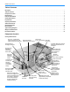
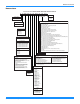
528194-YTG-O-0614 Table of Contents Description . . . . . . . . . . . . . . . . . . . . . . . . . . . . . . . . . . . . . . . . . . . . . . . . . . . . . . . . . . . . . . . . . . . . . . . . . . . . . . . . . . . . . . . . . . . . 1 Table of Contents . . . . . . . . . . . . . . . . . . . . . . . . . . . . . . . . . . . . . . . . . . . . . . . . . . . . . . . . . . . . . . . . . . . . . . . . . . . . . . . . . . . . . . . 2 Component Location . . . . . . . . . . . . . . . . . . . . . . . . . . . . . . . .
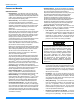
528194-YTG-O-0614 Nomenclature 6.5-12.5 Ton York® Model Number Nomenclature Z F 090 N10 A 2 A AA 6 0 1 2 4 A Product Style Product Category A = Style A B = Style B C = Style C Z = A/C, Single Pkg., R-410A Configuration Options (not required for all units) These four digits will not be assigned until a quote is requested, or an order placed. Product Identifier SS Drain Pan CPC Controller, DFS, APS F = 11.
528194-YTG-O-0614 Features and Benefits Standard Features • High Efficiency – High efficiency units reach as high as 11.2 EER. Gas/electric units have electronic spark ignition and power vented combustion with steady state efficiencies of 80%. These efficiencies exceed all legislated minimum levels and provide low operating costs. • Service Friendly – The Predator® incorporates a number of enhancements which improve serviceability. The motor and blower slide out of the unit as a common assembly.
28194-YTG-O-0614 sure switches and the freezestats must trip three times within two hours before the unit control board will lock out the associated compressor. • On Board Diagnostics - Each alarm will energize a trouble light on the thermostat, if so equipped, and flash an alarm code on the control board LED. Each high and low-pressure switch alarm as well as each freezestat alarm has its own flash code.
528194-YTG-O-0614 • Alternate Indoor Blower Motor - For applications with high static restrictions, units are offered with optional indoor motors that provide higher static output and/or higher airflow, depending upon the installer’s needs. • Variable Air Volume (VAV); 6-1/2 through 12-1/2 ton A factory-installed variable frequency drive (VFD), mounted in the Blower Access compartment, is used to control the speed of the indoor blower motor in order to maintain a constant static pressure in the supply duct.
528194-YTG-O-0614 setpoint, the valve modulates hot gas to the inlet of the evaporator. HGBP is standard on all units with VAV, and optional with constant-volume units. Control Options • BAS - Building Automation System Controls Simplicity® INTELLI-Comfort II™ Control - The York® Simplicity® INTELLI-Comfort II™ control is factory installed. It includes a supply air sensor, a return air sensor, and an outside air sensor.
528194-YTG-O-0614 • CO2 Sensor - Senses CO2 levels and automatically overrides the economizer when levels rise above the preset limits. • Dirty Filter Switch - This kit includes a differential pressure switch that energizes the fault light on the unit thermostat, indicating that there is an abnormally high pressure drop across the filters. • Coil Guard - Field installed decorative wire coil guard.
528194-YTG-O-0614 Accessories Field Installed Accessories - Non-Electrical MODEL 1BD0408 1CG0419 1CG0420 1CG0427 1CG0428 VOLTAGE All All All All All 1HG0411 1HG0415 1FE0411 1FF0414 1FF0415 1FL0402 1FL0423 1GP0405 1HA0442 1HA0443 1NP0442 1RC0470 1RC0471 All All All All All All All All All All All All All 1RC0472 All 1WC0412 All DESCRIPTION Burglar Bars, Downflow Coil Guard Coil Guard Coil Guard Coil Guard Hail Guard Kit Hail Guard Kit Flue Exhaust Extension Kit 2" only Metal Filter Frame Kit 2" only
528194-YTG-O-0614 Accessories (Continued) Field Installed Accessories - Fresh Air MODEL 1EH0408 1FA0413 1FA0414 1RD0411 2EC04700924 2EE04708324 VOLTAGE DESCRIPTION Barometric Relief Kit for Power Exhaust, Horizontal All Application All Manual Outside Air Damper 0-35%, Downflow All Manual Outside Air Damper 0-100%, Downflow All Barometric Relief Kit for Horizontal Applications All Dual Enthalpy Control Downflow Economizer, Slab type for ERV & Downflow All Applications, (no Barometric Relief or FA hood) Do
528194-YTG-O-0614 1” thick insulation coated on the airside. Either aluminum foil faced or elastometric rubber insulation shall be used in the unit’s compartments and be fastened to prevent insulation from entering the air stream. Cabinet doors shall be hinged with toolless access for easy servicing and maintenance. Full perimeter base rails shall be provided to assure reliable transit of equipment, overhead rigging, fork truck access and proper sealing on roof curb applications.
528194-YTG-O-0614 temperature of 40 ºF. Burners shall be of the in-shot type, constructed of aluminum-coated steel. All gas piping shall enter the unit cabinet at a single location, through either the side or bottom, without any field modifications. An integrated control board shall provide timed control of evaporator fan functioning and burner ignition. Heating section shall be provided with the following minimum protection: a. Primary and auxiliary high-temperature limit switches. b.
528194-YTG-O-0614 • DISCONNECT SWITCH - A disconnect can be factory installed on a cooling only units sized for the largest electric heat available. • STAINLESS STEEL HEAT EXCHANGER – For applications in a corrosive environment, this option provides a full stainless steel heat exchanger assembly. • SMOKE DETECTOR – A smoke detector can be factory mounted and wired in the supply and/or return air compartments.
528194-YTG-O-0614 Physical Data ZF078-150 Physical Data Models Component ZF078 ZF090 ZF102 ZF120 ZF150 6.5 7.5 8.5 10 12.5 Gross Capacity @ AHRI A point (Mbh) 81000 90000 104000 126000 156000 AHRI net capacity (Mbh) 78000 88000 100000 120000 150000 EER 11.2 11.2 11.2 11.2 11.0 IEER 12.51/12.32 12.51/12.32 12.51/12.32 12.31/12.12 12.31/12.12 IPLV 12.9 12.1 12.5 12.6 13.06 CFM 2500 2500 3400 4000 4050 System power (KW) 6.95 7.87 8.90 10.70 13.
528194-YTG-O-0614 ZF078-150 Physical Data (Continued) Models Component ZF078 ZF090 ZF102 ZF120 ZF150 6.5 7.5 8.5 10 12.5 2 2 2 2 4 Nominal Tonnage CONDENSER FAN DATA Quantity of Fans Fan diameter (Inch) 24 24 24 24 24 Type Prop Prop Prop Prop Prop Drive type Direct Direct Direct Direct Direct 2 2 2 2 4 1/3 3/4 3/4 3/4 3/4 Quantity of motors Motor HP each No.
528194-YTG-O-0614 ZF078-150 Unit Limitations Unit Limitations Size (Tons) 078 (6.5) 090 (7.5) 102 (8.5) 120 (10) 150 (12.
528194-YTG-O-0614 Capacity Performance ZF078-150 Cooling Capacities ZF078 (6.5 Ton) Air on Evaporator Coil CFM 1625 1950 2275 2600 2925 3250 1625 1950 2275 2600 2925 3250 WB (°F) Total Capacity1 (MBh) Total Input (kW)2 77 72 67 62 77 72 67 62 57 77 72 67 62 57 77 72 67 62 57 72 67 62 57 72 67 62 57 102.9 94.8 86.7 79.2 106.6 98.2 89.8 82.0 79.2 110.2 101.6 92.9 84.8 81.9 113.9 104.9 95.9 87.6 84.6 107.2 98.0 89.5 86.5 109.4 100.1 91.4 88.3 5.0 5.0 5.0 5.0 5.0 5.0 5.0 5.0 4.9 5.0 5.0 5.
528194-YTG-O-0614 ZF078 (6.5 Ton) (Continued) Air on Evaporator Coil CFM 1625 1950 2275 2600 2925 3250 WB (°F) Total Capacity1 (MBh) Total Input (kW)2 90 77 72 67 62 77 72 67 62 57 77 72 67 62 57 77 72 67 62 57 72 67 62 57 72 67 62 57 75.2 67.9 60.5 56.1 77.6 70.0 62.4 57.8 53.2 80.0 72.2 64.3 59.6 54.8 82.3 74.3 66.2 61.4 56.5 75.5 67.3 62.4 57.4 76.8 68.4 63.4 58.4 7.3 7.1 7.0 6.8 7.3 7.2 7.0 6.9 6.8 7.4 7.2 7.0 6.9 6.8 7.4 7.2 7.1 7.0 6.9 7.3 7.1 7.0 6.9 7.3 7.1 7.0 6.9 29.2 43.8 58.4 56.
528194-YTG-O-0614 ZF090 (7.5 Ton) Air on Evaporator Coil CFM 1875 2250 2625 3000 3375 3750 1875 2250 2625 3000 3375 3750 WB (°F) Total Capacity1 (MBh) Total Input (kW)2 90 77 72 67 62 77 72 67 62 57 77 72 67 62 57 77 72 67 62 57 72 67 62 57 72 67 62 57 119.9 110.5 101.1 91.2 123.0 113.3 103.6 93.6 95.1 126.0 116.1 106.2 95.9 97.4 129.1 118.9 108.8 98.2 99.8 122.5 112.0 101.1 102.8 126.1 115.3 104.1 105.8 6.0 6.0 6.0 6.1 6.0 6.0 6.1 6.1 6.0 6.1 6.1 6.1 6.1 6.0 6.1 6.1 6.1 6.1 6.1 6.1 6.
528194-YTG-O-0614 ZF090 (7.5 Ton) (Continued) Air on Evaporator Coil CFM 1875 2250 2625 3000 3375 3750 WB (°F) Total Capacity1 (MBh) Total Input (kW)2 90 77 72 67 62 77 72 67 62 57 77 72 67 62 57 77 72 67 62 57 72 67 62 57 72 67 62 57 87.3 79.0 70.7 64.2 89.5 81.0 72.5 65.8 68.5 91.6 82.9 74.3 67.4 70.1 93.8 84.9 76.0 68.9 71.8 86.6 77.6 70.3 73.2 88.3 79.1 71.7 74.7 8.6 8.4 8.1 8.0 8.6 8.4 8.2 8.1 8.0 8.7 8.5 8.3 8.1 8.1 8.7 8.5 8.3 8.2 8.2 8.6 8.4 8.2 8.2 8.6 8.4 8.2 8.2 35.4 50.6 65.8 64.
528194-YTG-O-0614 ZF102 (8.5 Ton) Air on Evaporator Coil CFM 2125 2550 2975 3400 3825 4250 2125 2550 2975 3400 3825 4250 WB (°F) Total Capacity1 (MBh) Total Input (kW)2 90 77 72 67 62 77 72 67 62 57 77 72 67 62 57 77 72 67 62 57 72 67 62 57 72 67 62 57 134.7 123.6 112.5 101.7 139.2 127.8 116.3 105.1 102.6 143.8 131.9 120.1 108.6 106.0 148.4 136.1 123.9 112.0 109.4 138.3 125.8 113.8 111.1 140.4 127.8 115.5 112.8 6.6 6.6 6.5 6.5 6.5 6.5 6.5 6.5 6.5 6.5 6.5 6.5 6.5 6.5 6.5 6.5 6.5 6.5 6.
528194-YTG-O-0614 ZF102 (8.5 Ton) (Continued) Air on Evaporator Coil CFM 2125 2550 2975 3400 3825 4250 WB (°F) Total Capacity1 (MBh) Total Input (kW)2 90 77 72 67 62 77 72 67 62 57 77 72 67 62 57 77 72 67 62 57 72 67 62 57 72 67 62 57 103.0 92.4 81.7 78.2 103.6 92.9 82.1 78.6 79.5 104.2 93.4 82.6 79.1 80.0 104.8 93.9 83.1 79.5 80.4 96.1 85.0 81.4 82.3 98.3 87.0 83.2 84.2 9.4 9.1 8.9 8.8 9.4 9.2 8.9 8.8 8.9 9.5 9.2 9.0 8.9 8.9 9.5 9.3 9.0 8.9 9.0 9.3 9.1 8.9 9.0 9.3 9.1 9.0 9.0 37.0 57.6 78.
528194-YTG-O-0614 ZF120 (10 Ton) Air on Evaporator Coil CFM 2500 3000 3500 4000 4500 5000 2500 3000 3500 4000 4500 5000 WB (°F) Total Capacity1 (MBh) Total Input (kW)2 90 77 72 67 62 77 72 67 62 57 77 72 67 62 57 77 72 67 62 57 72 67 62 57 72 67 62 57 165.2 149.2 133.2 121.8 170.9 154.3 137.7 125.9 120.2 176.6 159.4 142.3 130.1 124.2 182.2 164.5 146.8 134.3 128.2 168.0 149.9 137.1 130.9 171.4 153.0 139.9 133.5 7.4 7.5 7.5 7.5 7.4 7.4 7.4 7.5 7.4 7.4 7.4 7.4 7.5 7.4 7.3 7.4 7.4 7.4 7.4 7.
528194-YTG-O-0614 ZF120 (10 Ton) (Continued) Air on Evaporator Coil CFM 2500 3000 3500 4000 4500 5000 WB (°F) Total Capacity1 (MBh) Total Input (kW)2 90 77 72 67 62 77 72 67 62 57 77 72 67 62 57 77 72 67 62 57 72 67 62 57 72 67 62 57 117.2 106.1 95.0 85.5 120.1 108.7 97.4 87.5 90.8 122.9 111.3 99.7 89.6 93.0 125.8 113.9 102.0 91.7 95.1 115.9 103.8 93.3 96.8 117.9 105.6 95.0 98.5 11.2 10.8 10.4 10.1 11.2 10.9 10.5 10.2 10.3 11.3 10.9 10.6 10.3 10.4 11.4 11.0 10.6 10.4 10.5 11.1 10.7 10.4 10.
528194-YTG-O-0614 ZF150 (12.5 Ton) Air on Evaporator Coil CFM 3125 3750 4375 5000 5625 6250 3125 3750 4375 5000 5625 6250 WB (°F) Total Capacity1 (MBh) Total Input (kW)2 90 77 72 67 62 77 72 67 62 57 77 72 67 62 57 77 72 67 62 57 72 67 62 57 72 67 62 57 192.8 179.7 166.6 150.6 200.7 187.1 173.4 156.8 152.3 208.7 194.5 180.2 163.0 158.3 216.6 201.8 187.1 169.2 164.3 203.6 188.7 170.7 165.7 205.4 190.4 172.2 167.2 10.1 9.8 9.6 9.5 10.1 9.9 9.6 9.5 9.5 10.1 9.9 9.7 9.6 9.5 10.1 9.9 9.7 9.
528194-YTG-O-0614 ZF150 (12.5 Ton) (Continued) Air on Evaporator Coil CFM 3125 3750 4375 5000 5625 6250 WB (°F) Total Capacity1 (MBh) Total Input (kW)2 90 77 72 67 62 77 72 67 62 57 77 72 67 62 57 77 72 67 62 57 72 67 62 57 72 67 62 57 152.8 139.4 125.9 117.0 158.0 144.1 130.1 121.0 119.1 163.2 148.8 134.4 125.0 123.0 168.3 153.5 138.7 128.9 126.9 156.2 141.1 131.2 129.2 158.9 143.6 133.5 131.4 14.9 14.8 14.7 14.5 14.9 14.8 14.7 14.5 14.6 14.9 14.8 14.7 14.6 14.6 15.0 14.9 14.8 14.6 14.6 14.
528194-YTG-O-0614 Airflow Performance ZF078-150 Side Duct Application ZF078 (6.5 Ton) Side Duct Air Flow (CFM) 1800 2000 2200 2400 2600 2800 3000 3200 3400 Available External Static Pressure - IWG1 0.2 0.4 0.6 0.8 1.0 1.2 1.4 1.6 1.8 2.0 RPM BHP RPM BHP RPM BHP RPM BHP RPM BHP RPM BHP RPM BHP RPM BHP RPM BHP RPM BHP 751 776 804 835 869 906 945 987 1030 Field Supplied Drive 0.22 813 0.43 872 0.35 838 0.56 897 0.50 866 0.71 925 0.66 897 0.87 956 0.84 931 1.05 990 1.03 968 1.25 1027 1.25 1007 1.46 1066 1.
528194-YTG-O-0614 ZF120 (10 Ton) Side Duct Air Flow (CFM) 2600 2800 3000 3200 3400 3600 3800 4000 4200 4400 4600 4800 5000 Available External Static Pressure - IWG1 0.2 0.4 0.6 0.8 1.0 1.2 1.4 1.6 1.8 2.0 RPM BHP RPM BHP RPM BHP RPM BHP RPM BHP RPM BHP RPM BHP RPM BHP RPM BHP RPM BHP Field Supplied Drive 675 0.53 726 0.74 686 0.63 738 0.84 699 0.75 750 0.96 713 0.88 764 1.09 728 1.02 779 1.23 745 1.18 796 1.39 763 1.36 815 1.57 783 1.55 835 1.76 805 1.77 856 1.98 828 2.00 879 2.21 852 2.25 904 2.46 879 2.
528194-YTG-O-0614 ZF078-150 Bottom Duct Application ZF078 (6.5 Ton) Bottom Duct Air Flow (CFM) 1800 2000 2200 2400 2600 2800 3000 3200 3400 Available External Static Pressure - IWG1 0.2 0.4 0.6 0.8 1.0 1.2 1.4 1.6 1.8 2.0 RPM BHP RPM BHP RPM BHP RPM BHP RPM BHP RPM BHP RPM BHP RPM BHP RPM BHP RPM BHP Field Supplied Drive 775 0.31 850 0.53 803 0.45 878 0.67 838 0.60 913 0.82 878 0.78 953 1.00 923 0.98 997 1.20 971 1.20 1046 1.42 1023 1.44 1097 1.66 1077 1.71 1151 1.93 1133 1.99 1208 2.
528194-YTG-O-0614 ZF120 (10 Ton) Bottom Duct Air Flow (CFM) 2600 2800 3000 3200 3400 3600 3800 4000 4200 4400 4600 Available External Static Pressure - IWG1 0.2 0.4 0.6 0.8 1.0 1.2 1.4 1.6 1.8 2.0 RPM BHP RPM BHP RPM BHP RPM BHP RPM BHP RPM BHP RPM BHP RPM BHP RPM BHP RPM BHP Field Supplied Drive 722 0.83 744 0.97 769 1.13 797 1.32 828 1.52 861 1.75 897 2.00 935 2.27 976 2.57 1019 2.88 1065 3.22 Standard 2 HP & Drive 776 798 823 851 882 915 951 989 1030 1073 1119 0.97 1.12 1.28 1.46 1.67 1.90 2.15 2.
528194-YTG-O-0614 RPM Selection Size (Tons) 078 (6.5) Model ZF 090 (7.5) ZF 102 (8.5) ZF 120 (10) ZF 150 (12.5) ZF HP 1.5 2 1.5 3 2 3 2 3 3 5 Max BHP 1.73 2.30 1.73 3.45 2.30 3.45 2.30 3.45 3.45 5.
528194-YTG-O-0614 Drive Selection 1. Determine side or bottom supply duct Application. 2. Determine desired airflow. 3. Calculate or measure the amount of external static pressure. 4. Using the operating point determined from steps 1, 2 & 3, locate this point on the appropriate supply air blower performance table. (Linear interpolation may be necessary.) 5. Noting the RPM and BHP from step 4, locate the appropriate motor and, or drive on the RPM selection table. 6.
528194-YTG-O-0614 Altitude/Temperature Correction Factors Air Temp. 40 50 60 70 80 90 100 0 1.060 1.039 1.019 1.000 0.982 0.964 0.946 1000 1.022 1.002 0.982 0.964 0.947 0.929 0.912 2000 0.986 0.966 0.948 0.930 0.913 0.897 0.880 3000 0.950 0.931 0.913 0.896 0.880 0.864 0.848 4000 0.916 0.898 0.880 0.864 0.848 0.833 0.817 Altitude (Ft.) 5000 0.882 0.864 0.848 0.832 0.817 0.802 0.787 6000 0.849 0.832 0.816 0.801 0.787 0.772 0.758 7000 0.818 0.802 0.787 0.772 0.758 0.744 0.730 8000 0.788 0.772 0.
528194-YTG-O-0614 Gas Heat Minimum Supply Air Supply Air (CFM) Size (Tons) Model 078 (6.5) 090 (7.5) 102 (8.5) 120 (10) 150 (12.
528194-YTG-O-0614 Electric Heat Multipliers Voltage Nominal kW Capacity Multipliers1 Applied 208 230 460 575 240 480 600 0.75 0.92 0.92 0.92 1. Electric heaters are rated at nominal voltage. Use this table to determine the electric heat capacity for heaters applied at lower voltages. Sound Performance Indoor Sound Power Levels Size (Tons) 078 (6.5) 090 (7.5) 102 (8.5) 120 (10) 150 (12.
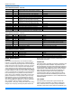
528194-YTG-O-0614 Electrical Data ZF078-150 Standard Motor - Without Powered Convenience Outlet Size (Tons) Volt Compressors (each) RLA LRA MCC OD Fan Motors (each) Supply Blower Motor Pwr Exh Motor Pwr Conv Outlet FLA FLA FLA FLA 208 9.3 68 14.5 1.5 6.0 5.5 0 230 9.3 68 14.5 1.5 6.0 5.5 0 460 4.9 34 7.7 0.8 3.0 2.2 0 575 3.8 28 6 0.6 2.4 1.8 0 208 11.9 88 18.5 3.5 6.0 5.5 0 230 11.9 88 18.5 3.5 6.0 5.5 0 460 5.2 44 8.1 1.6 3.0 2.
528194-YTG-O-0614 ZF078-150 Standard Motor - Without Powered Convenience Outlet (Continued) Size (Tons) Volt Compressors (each) RLA LRA MCC OD Fan Motors (each) Supply Blower Motor Pwr Exh Motor Pwr Conv Outlet FLA FLA FLA FLA 208 13.9 110 21.7 3.5 6.8 5.5 0 230 13.9 110 21.7 3.5 6.8 5.5 0 460 7.4 55 11.5 1.6 3.4 2.2 0 575 5.6 43 8.7 1.3 2.7 1.8 0 208 23.1 160 36 3.5 9.6 5.5 0 230 23.1 160 36 3.5 9.6 5.5 0 460 12.2 87 19 1.6 4.8 2.
528194-YTG-O-0614 ZF078-150 Hi Static Motor - Without Powered Convenience Outlet Size (Tons) Volt Compressors (each) RLA LRA MCC OD Fan Motors (each) Supply Blower Motor Pwr Exh Motor Pwr Conv Outlet FLA FLA FLA FLA 208 9.3 68 14.5 1.5 6.8 5.5 0 230 9.3 68 14.5 1.5 6.8 5.5 0 460 4.9 34 7.7 0.8 3.4 2.2 0 575 3.8 28 6 0.6 2.7 1.8 0 208 11.9 88 18.5 3.5 9.6 5.5 0 230 11.9 88 18.5 3.5 9.6 5.5 0 460 5.2 44 8.1 1.6 4.8 2.2 0 575 4.8 36 7.
528194-YTG-O-0614 ZF078-150 Hi Static Motor - Without Powered Convenience Outlet (Continued) Size (Tons) Volt Compressors (each) RLA LRA MCC OD Fan Motors (each) Supply Blower Motor Pwr Exh Motor Pwr Conv Outlet FLA FLA FLA FLA 208 13.9 110 21.7 3.5 9.6 5.5 0 230 13.9 110 21.7 3.5 9.6 5.5 0 460 7.4 55 11.5 1.6 4.8 2.2 0 575 5.6 43 8.7 1.3 3.9 1.8 0 208 23.1 160 36 3.5 15.2 5.5 0 230 23.1 160 36 3.5 15.2 5.5 0 460 12.2 87 19 1.6 7.6 2.
528194-YTG-O-0614 ZF078-150 Standard Motor - With Powered Convenience Outlet Size (Tons) Volt Compressors (each) RLA LRA MCC OD Fan Motors (each) Supply Blower Motor Pwr Exh Motor Pwr Conv Outlet FLA FLA FLA FLA 208 9.3 68 14.5 1.5 6.0 5.5 10 230 9.3 68 14.5 1.5 6.0 5.5 10 460 4.9 34 7.7 0.8 3.0 2.2 5 575 3.8 28 6 0.6 2.4 1.8 4 208 11.9 88 18.5 3.5 6.0 5.5 10 230 11.9 88 18.5 3.5 6.0 5.5 10 460 5.2 44 8.1 1.6 3.0 2.2 5 575 4.8 36 7.
528194-YTG-O-0614 ZF078-150 Standard Motor - With Powered Convenience Outlet (Continued) Size (Tons) Volt Compressors (each) RLA LRA MCC OD Fan Motors (each) Supply Blower Motor Pwr Exh Motor Pwr Conv Outlet FLA FLA FLA FLA 208 13.9 110 21.7 3.5 6.8 5.5 10 230 13.9 110 21.7 3.5 6.8 5.5 10 460 7.4 55 11.5 1.6 3.4 2.2 5 575 5.6 43 8.7 1.3 2.7 1.8 4 208 23.1 160 36 3.5 9.6 5.5 10 230 23.1 160 36 3.5 9.6 5.5 10 460 12.2 87 19 1.6 4.8 2.
528194-YTG-O-0614 ZF078-150 Hi Static Motor - With Powered Convenience Outlet Size (Tons) Volt Compressors (each) RLA LRA MCC OD Fan Motors (each) Supply Blower Motor Pwr Exh Motor Pwr Conv Outlet FLA FLA FLA FLA 208 9.3 68 14.5 1.5 6.8 5.5 10 230 9.3 68 14.5 1.5 6.8 5.5 10 460 4.9 34 7.7 0.8 3.4 2.2 5 575 3.8 28 6 0.6 2.7 1.8 4 208 11.9 88 18.5 3.5 9.6 5.5 10 230 11.9 88 18.5 3.5 9.6 5.5 10 460 5.2 44 8.1 1.6 4.8 2.2 5 575 4.8 36 7.
528194-YTG-O-0614 ZF078-150 Hi Static Motor - With Powered Convenience Outlet (Continued) Size (Tons) Volt Compressors (each) RLA LRA MCC OD Fan Motors (each) Supply Blower Motor Pwr Exh Motor Pwr Conv Outlet FLA FLA FLA FLA 208 13.9 110 21.7 3.5 9.6 5.5 10 230 13.9 110 21.7 3.5 9.6 5.5 10 460 7.4 55 11.5 1.6 4.8 2.2 5 575 5.6 43 8.7 1.3 3.9 1.8 4 208 23.1 160 36 3.5 15.2 5.5 10 230 23.1 160 36 3.5 15.2 5.5 10 460 12.2 87 19 1.6 7.6 2.
528194-YTG-O-0614 Typical Wiring Diagrams ZF078-150 Typical Wiring Diagrams Typical ZF078-120 Cooling Unit with Gas Heat 230 Volt Wiring Diagram 44 Johnson Controls Unitary Products
528194-YTG-O-0614 Typical ZF078-120 Cooling Unit with Gas Heat 460/575 Volt Wiring Diagram Johnson Controls Unitary Products 45
528194-YTG-O-0614 Typical ZF078-120 Cooling Unit with/without Electric Heat Wiring 46 Johnson Controls Unitary Products
528194-YTG-O-0614 Typical ZF150 Cooling Unit with Gas Heat 230 Volt Wiring Diagram Johnson Controls Unitary Products 47
528194-YTG-O-0614 Typical ZF150 Cooling Unit with Gas Heat 460/575 Volt Wiring Diagram 48 Johnson Controls Unitary Products
528194-YTG-O-0614 Typical ZF150 Cooling Unit with/without Electric Heat Wiring Diagram Johnson Controls Unitary Products 49
528194-YTG-O-0614 Typical ZF078-150 Factory Installed VFD (Option) 50 Johnson Controls Unitary Products
528194-YTG-O-0614 Typical ZF078-150 Factory Installed VFD with Manual Bypass (Option) Johnson Controls Unitary Products 51
8194-YTG-O-0614 Typical ZF078-150 Factory Installed VFD with CCS Control (Option) 52 Johnson Controls Unitary Products
528194-YTG-O-0614 Typical ZF078-150 Factory Installed VFD and Manual Bypass with CCS Control (Option) Johnson Controls Unitary Products 53
528194-YTG-O-0614 Typical ZF078-150 BAS Ready Unit with Factory Installed VFD (Option) 54 Johnson Controls Unitary Products
528194-YTG-O-0614 Typical ZF078-150 BAS Ready Unit with Factory Installed VFD and Manual Bypass (Option) Johnson Controls Unitary Products 55
528194-YTG-O-0614 Typical ZF078-150 VFD Ready Unit (Option) 56 Johnson Controls Unitary Products
528194-YTG-O-0614 Weights and Dimensions ZF078-150 Unit Weights Unit 4 Point Load Weight Unit 6 Point Load Weight FRONT FRONT LEFT LEFT B C B A A D C E F D Y X FRONT LEFT Weight (lbs.) Center of Gravity Size Model Shipping Operating X Y (Tons) 078 ZF 865 860 38 24 (6.5) 090 ZF 885 860 38 24 (7.5) 102 ZF 1012 1007 38 24 (8.5) 120 ZF 1065 1060 38 24 (10) 150 ZF 1258 1253 47 25 (12.5) Johnson Controls Unitary Products 4 Point Load Location (lbs.) A B C D A 6 Point Load Location (lbs.
528194-YTG-O-0614 ZF078-150 Unit Accessory Weights Unit Accessory Economizer Power Exhaust Electric Heat1 Gas Heat2 Variable Frequency Drive3 Weight (lbs.) Shipping Operating 90 85 40 35 49 49 110 110 30 30 1. Weight given is for the maximum heater size available (54KW). 2. Weight given is for the maximum number of tube heat exchangers available (8 tube). 3. Weight includes mounting hardware, controls and manual bypass option (ZF Only). ZF078-150 Unit Dimensions ZF078 - 120 29.69 15.25 15.38 59.
528194-YTG-O-0614 ZF150 45.64 14.92 4X Ø 24.38 14.92 58.09 14.92 29.95 30.11 B SEE DETAIL A FOR GAS INLET A C D E 11.38 F 59.00 SEE DETAIL B FOR DRAIN LOCATION 4.19 27.31 LEFT 21.19 89.00 FRONT ZF078-150 Unit Physical Dimensions Unit Model Number 078 090 102 120 150 Johnson Controls Unitary Products A 42 42 50 3/4 50 3/4 50 3/4 B 89 89 89 89 119 1/2 Dimension (in.
528194-YTG-O-0614 Detail A 3.184 3.184 Gas Pipe Inlet Gas Pipe Inlet Ø 2.000 Ø 2.000 Gas Exhaust Vent Gas Exhaust Vent Ø 3.126 Ø 3.126 17.541 14.594 7.715 7.705 4.737 4.727 42” CABINET 50 3/4” CABINET Detail B 5-3/8 3/4” FPT ZF078-150 Unit Clearances Direction Top1 Front Rear Distance (in.) 72 36 36 Direction Right Left Bottom2 Distance (in.) 12 36 0 1. Units must be installed outdoors. Over hanging structure or shrubs should not obscure condenser air discharge outlet. 2.
528194-YTG-O-0614 ZF078-150 Unit Bottom Duct Openin 89 32 11/16 6 13/16 6 13/16 SUPPLY AIR RETURN AIR 27 1/2 LEFT 18 24 RIGHT 21 20 1/8 19 1/8 17 1/8 12 5/16 Bottom condensate drain 14 1/2 25 9/16 Bottom gas supply entry 16 3/8 18 1/16 FRONT TOP VIEW Bottom power, control and convenience outlet wiring entry 3X Ø 0.875 Ø 2.
528194-YTG-O-0614 ZF078-150 Unit Electrical Entry Disconnect Swith Cover Power Entry Ø 2-1/2 Control Entry Ø 7/8 Power Entry Ø 2-1/2 Convenience Outlet Cover Convenience Outlet Power Entry Ø 7/8 FRONT ZF078-120 Unit Side Duct Openings Dot Plugs 18-1/4 Return Air A Supply Air D B 2-31/32 5-5/32 C 31-11/16 62 Johnson Controls Unitary Products
528194-YTG-O-0614 ZF150 Unit Side Duct Openings Dot Plugs 18-1/4 A D B 5-5/32 2-7/8 C 31-5/8 ZF Side Duct Dimensions Unit Model Number 078 090 102 120 150 A 27 3/4 27 3/4 28 1/4 28 1/4 28 1/4 Dimension (in.
528194-YTG-O-0614 ZF078-150 Unit Accessory Dimensions ZF078-150 Roof Curb RIGHT 80-5/8 INSULATED DECK UNDER CONDENSER SECTION 20 SUPPLY 20 6 RETURN 2 TYP.
528194-YTG-O-0614 ZF078-150 Economizer Assembly 58 1/4 88 1/4 24 3/4 Tall Units 26 1/8 Short Units 32 1/16 39 1/2 OR 47 1/2 Fresh Air Hood For Economizer Outside Air Intake Hood 35 3/4 Relief Hood For Power Exhaust Or Barometric Relief 26 Johnson Controls Unitary Products 25 3/4 23 3/4 31 7/8 65
528194-YTG-O-0614 Economizer Options Economizer Usage Application Cabinet Height Description Model Side Return All Horizontal economizer without barometric relief 2EE047060241 42" Slab Economizer, 42” tall cabinet 2EE047075242 50" Slab Economizer, 50” tall cabinet 2EE047083242 ERV or End Return 1. Barometric relief must be ordered separately and installed in duct work. 2. Barometric relief or fresh air hood not included. Must be ordered separately.
Slab Economizer End Return W/Power Exhaust Fresh Air Hood Field Installed Duct Work Slab Low Leak Economizer Power Exhaust Barometric Relief Damper Barometric Relief Hood Subject to change without notice. Printed in U.S.A. Copyright © 2014 by Johnson Controls, Inc. All rights reserved.