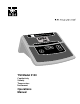
CONDUCTIVITY INSTRUMENT µS C YSI Model 3100 Conductivity Salinity Temperature Instrument Operations Manual
Table of Contents 1. Introduction..............................................................................................................................................1 1.1 Capabilities ...................................................................................................................................................... 1 1.2 Controls.........................................................................................................................................................
Small Sample Measurements ........................................................................................................................ 25 Conductivity System Accuracy Considerations ............................................................................................ 26 7.3 Salinity ........................................................................................................................................................... 26 7.4 Temperature ..................................
1. Introduction The YSI Model 3100 is a microprocessor based instrument designed to perform laboratory measurement of conductivity, salinity and temperature. The instrument’s push button operation makes it simple to use. The Model 3100's microprocessor allows the system to be easily calibrated with the press of a few keys. Additionally, the microprocessor performs a self-diagnostic routine each time the instrument is turned on.
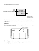
1.2 Controls Front Panel The front panel of the instrument contains the display and keypad as shown below. 3100 CONDUCTIVITY INSTRUMENT 12.85 uS 22.
The following diagram shows the typical display. Conductivity: mS/cm uS/cm Temperature compensated conductivity: mS/cm uS/cm 10.00 µS 24.8 °C Salinity: ppt Temperature: °C NOTE: Flashing °C symbol indicates temperature compensation is enabled. The [Mode] key is used to select the current display mode. Mode choices are conductivity, temperature compensated conductivity or salinity. Temperature is always displayed at the bottom of the screen.
Cell Connection The connector for the cell is a 7-pin mini DIN connector and is marked with an arrow to show proper alignment. Be sure to align the arrows when plugging in the cell. YSI 3200 series cells utilize a mini DIN connector that plugs directly into the 3100. If, however, you have a YSI 3400 series cell, the YSI 3232 cell adapter will be required. The YSI 3232 adapter mounts on the post on the rear of the 3100. It has a 7-pin mini-DIN connector and two binding posts.
3. System Configuration and Operation 3.1 Turning the Instrument On Plug the power supply into its mating connector on the back of the instrument. Depress the (on/off) key to turn the instrument on. The instrument will activate all segments of the display for a few seconds, which will be followed by a self test procedure which will last for several more seconds. During this power on self test sequence, the instrument’s microprocessor is verifying that the instrument is working properly.
Conductivity 16.34 µS 24.8 °C 3.3 Temperature: °C Configure the 3100 Before operating the 3100, or whenever you change cells, you must configure the 3100 to match the cell used. You must enter the manufacturer’s stated (or your manually calculated) cell constant (K) as shown below (Cell Constant). The default configuration is as follows: • • Cell constant of K = 1 Temperature compensation corrected to 25°C using a coefficient of 1.91%/°C.
1.00 Cell constant CAL 4. Use the [UP ARROW] or [DOWN ARROW] keys to change the value to the desired new cell constant. 0.10 New cell constant CAL 5. Press the [ENTER] key. The word “SAVE” will flash across the display for a second to indicate that your change has been accepted. The 3100 will return to normal operation mode. SAVE 3.
To choose one of the measurement modes (temperature is always displayed), simply press and release the [MODE] key. Carefully observe the small legends at the far right side of the LCD. Temperature Compensated Conductivity with °C Conductuctivity with °C Salinity with °C If the instrument is reading Temperature compensated conductivity, the large numbers on the display will be followed by either a µS or mS and the small portion of the display will show the o C flashing on and off.
3.5 Making Measurements After setting up the 3100 instrument and cell as described earlier, the following basic steps should be used to make measurements. 1. Verify that the 3100 is properly set up to use the current cell by measuring, or calibrating with, a standard conductivity solution. See section 4.1 Cell Calibration. 2. Immerse the cell in the solution to be measured. 3. Gently tap the cell to remove any air bubbles and dip the cell in the solution 2 or 3 times to ensure proper wetting.
4. Advanced Setup For highest accuracy, the 3100 and cell may be calibrated as a system using standard conductivity calibration solutions. See the following section, 4.1 Cell Calibration, for details. The default temperature compensation settings of the YSI Model 3100 are appropriate for the vast majority of measurement applications. However, some measurement applications require very specific measurement criteria.
4. Gently tap the cell to remove any air bubbles and dip the cell in the solution 2 or 3 times to ensure proper wetting. If using a flow through or fill cell, be certain it is completely full. 5. Allow at least 60 seconds for the temperature reading to become stable. 6.
4.2 Temperature Coefficient Follow these steps to modify the temperature coefficient of the Model 3100. 1. Press and release the [DOWN ARROW] and [MODE] keys at the same time. The CAL symbol will appear at the bottom left of the display and the large portion of the display will % show 1.91 (or a value set previously using Advanced Setup). 1.91% Temperature coefficient 22.7 °C CAL CAL symbol 2. Use the [UP ARROW] or [DOWN ARROW] key to change the value to the desired new temperature coefficient. 1.
The CAL symbol will appear at the bottom left of the display and the large portion of the % display will show 1.91 (or a value set previously using Advanced Setup). 2. Press and release the [MODE] key. The large portion of the display will show 25.0C (or a value set previously using Advanced Setup). 25.0C Reference temperature 22.7 CAL 3. Use the [UP ARROW] or [DOWN ARROW] key to change the value to the desired new reference temperature (the allowable range is 15°C to 25°C). 15.
NOTE: You may see an error message in some manual ranges if the range selected is not adequate for the sample you are measuring. rErr mS Range error message 24.8 °C If this happens, simply press and release the [ENTER] key again until a range is selected which is suitable for your sample. If you get lost and don’t know if you’re in a manual range or autoranging, simply turn the instrument off and back on. The instrument will default to autoranging when first turned on.
5. Maintenance 5.1 Cell Cleaning and Storage The single most important requirement for accurate and reproducible results in conductivity measurement is a clean cell. A dirty cell will change the conductivity of a solution by contaminating it. To clean a conductivity cell: 1. Dip or fill the cell with cleaning solution and agitate for two to three minutes. Any one of the foaming acid tile cleaners, such as Dow Chemical Bathroom Cleaner, will clean the cell adequately.
2. Press both the [UP ARROW] and [MODE] keys at the same time. The large portion of the display will show “PLA” flashing, indicating that platinization is in process. PLA 3. After the platinization process is complete (about 30 minutes), the 3100 will return to normal mode. Remove the cell from the platinizing solution. If you want to stop the platinization before 30 minutes have passed, press both the [UP ARROW] and [MODE] keys at the same time to abort. 4.
6. Troubleshooting Error Messages The instrument performs a Power On Self Test each time it is turned on. The following error messages are provided to facilitate troubleshooting. They appear on the LCD when an error is detected. SYMPTOM 1. Instrument will not turn on 2. Instrument will not calibrate 3. 4. 5. 6. 7.
SYMPTOM 8. 9. Main Display reads “LErr” Secondary Display reads “Err ra” 10. Secondary Display reads “Err ro” 11. Secondary Display reads “udr” 12. Secondary Display reads “ovr” 13. Secondary Display reads “rEr” POSSIBLE CAUSE ACTION • Adjust user defined temperature coefficient (see 4.2 Temperature Coefficient) or reference temperature (see 4.3 Reference Temperature) • Use a YSI 3200 series cell or turn off temperature compensation.
7. Principles of Operation 7.1 3100 Principles The YSI 3100 obtains a conductance value by varying the amplitude of a square-wave current forced through the cell so that the center-sampled magnitude of the cell voltage for each halfcycle is constant and is equal to a reference voltage. In this condition, the current and conductance are directly proportional. To convert this conductance value to conductivity, it is multiplied by the cell constant which has units of reciprocal cm (cm-1).
normal to the current flow (A): d Cell Constant = K = A Therefore, conductivity equals conductance multiplied by the cell constant. ℵ = k ×K Example: For an observed conductance of 100 micro mhos (100 microsiemens) and a cell constant of 0.1/cm ℵ = k × K = 100 µ mho × 0.1 / cm = 10 µ mho / cm In SI units, the cell constant K=0.
Choosing a Conductivity Cell Decide which cell will be the most useful for your conditions by considering the conductivity of the solution you want to measure, the size of the sample and if temperature measurement or compensation is required. 3252, 3417 3418 3256, 3402 3255, 3446 3401 3440 3253, 3403 3254, 3445 0 0.1 1.0 10 1000 µS/cm 1 100 10 100 1000 mS/cm Conductivity The chart above reflects general guidelines. Refer to cell specifications for details.
Cell Constant Calculation YSI 3200 and 3400 Series conductivity cells are calibrated to ± 1% of nominal by means of a YSI transfer standard traceable to OIML Recommendation 56 and NIST. Anytime the condition of the conductivity cell changes, it is possible that the cell constant has also changed. Therefore, you should calibrate your system regularly.
Conductivity Law Solution Conductivity S/cm or mho/cm mS/cm or mmho/cm µS/cm or µmho/cm Instrument Conductance S or mho mS or mmho µS or µmho = = = CELL CONSTANT = × × × Cell Constant 1/cm 1/cm 1/cm SOLUTION CONDUCTIVITY METER CONDUCTANCE METER CONDUCTANCE = SOLUTION CONDUCTIVITY CELL CONSTANT Low Conductivity Measurements When measuring reagent grade water (deionized) or other substances having extremely low conductivity, it is recommend that a flow-through cell having a constant of 0.
General Conductivity Measurement Precautions After selecting the proper cell, observe the following precautions to ensure accurate, repeatable results: 1. The cell must be clean before making any measurements. When working with substances having low conductivity, extraordinary cleanliness may be required. 2. Soak cells that have been stored dry in deionized water before use. 3. Immerse the cell in the solution deep enough to submerge the vent hole. 4. The electrode chamber should be free of trapped air. 5.
change in conductivity for each degree change in temperature (%/°°C), which is called the temperature coefficient. In extreme cases, the temperature coefficient may have a value as high as 7%/°C. Each conductive ion has a different temperature coefficient. When practical, control the temperature of the solution to be analyzed. For high precision work (±1%), maintain the temperature at 25°C ± 0.1°C. For routine lab work, 25°C ± 0.5°C may be acceptable.
The cell you use for small sample applications depends upon the quantity of solution available and the conductivity of the solution. The 3401 cell (K=1.0/cm) requires 15 mL, the 3256 and 3402 cells (K=0.1/cm) require 12 mL, the 3253 and 3403 cells (K=1.0/cm) require 3 mL, and the 3252 and 3417 cells (K=1.0/cm) require 1 mL of sample. When a dip cell is used as a fill cell, the cell's vent hole is sealed and the electrode chamber is inverted and filled with solution, changing the cell constant (K).
7.4 Temperature The Model 3100 system utilizes a thermistor of sintered metallic oxide which changes predictably in resistance with temperature variation. The algorithm for conversion of resistance to temperature is built-in to the Model 3100 software, and accurate temperature readings in degrees Celsius or Fahrenheit are provided automatically. No calibration or maintenance of the temperature sensor is required. 7.
Cable Series Resistance and Shunt Capacitance YSI 3200 series cells utilize a 4-wire connection virtually eliminating errors due to cable resistance. The short cables provided as a part of regular cell assemblies will introduce negligible error in most measurements. However, if longer cables are required or if extraordinary accuracy is necessary, special precautions may be prudent.
8. Warranty & Repair YSI Model 3100 Instruments are warranted for two years from date of purchase by the end user against defects in materials and workmanship. YSI cells and cables are warranted for one year from date of purchase by the end user against defects in material and workmanship. Within the warranty period, YSI will repair or replace, at its sole discretion, free of charge, any product that YSI determines to be covered by this warranty.
8.1 Cleaning Instructions NOTE: Before they can be serviced, equipment exposed to biological, radioactive, or toxic materials must be cleaned and disinfected. Biological contamination is presumed for any instrument, probe, or other device that has been used with body fluids or tissues, or with waste water. Radioactive contamination is presumed for any instrument, probe or other device that has been used near any radioactive source.
8.2 Packing Instructions 1. Clean and decontaminate items to insure the safety of the handler. 2. Complete and include the Cleaning Certificate. 3. Place the product in a plastic bag to keep out dirt and packing material. 4. Use a large carton, preferably the original, and surround the product completely with packing material. 5. Insure for the replacement value of the product.
8.3 Disassembly/Assembly Procedures NOTE: The following procedure should only be performed by a qualified service technician. C Case Disassembly • • • • • While applying slight separation force to the front, curved edge of the case near one corner, use a small straight-blade screwdriver to release the snap (A) on the same side. When that snap releases, keep applying the separation force, and use the screwdriver to release the front snap (B) nearest the same corner.
9. Accessories and Replacement Parts YSI Item # Description Comments 003208 3208 Power Supply, 115 VAC 003209 3209 Power Supply, 240 VAC 031008 Overlay, Window 031009 Overlay, Keypad 051009 Window 113117 Board Assy, PC, Main 055214 LCD 113138 Case Assy, Upper 111027 Case Assy, Lower 003226 Weight, SS 051043 Foot, Rubber, Self-Stick 032061 Gasket, Connector, Cell 032063 Gasket, Connector, Power 051025 Standoff, .
9.1 YSI Conductivity Cells YSI 3200 series conductivity cells have a built in temperature sensor for temperature measurement and automatic temperature compensation. Dip, fill and flow-through conductivity cells are available, each utilizing platinized platinum iridium electrodes. These cells have the following specifications: Part cgs Cell Number Constant 3200 Series Dip Cells 3252 1.0/cm SI Cell Constant Material Overall Length O.D. 100/m ABS plastic glass glass 146 mm 3253 1.0/cm 100/m 3256 0.
9.2 Standard Calibrator Solutions YSI manufactures NIST-traceable conductivity calibrator solutions for calibration purposes. The following conductivity calibrator solutions are available from YSI. Part Number 3161 3163 3165 3167 3168 3169 Size 1 quart 1 quart 1 quart 8 pints 8 pints 8 pints Conductivity at 25.00°°C 1,000 µ mho/cm ± 0.50% 10,000 µ mho/cm ± 0.25% 100,000 µ mho/cm ± 0.25% 1,000 µ mho/cm ± 1.0% 10,000 µ mho/cm ± 1.0% 50,000 µ mho/cm ± 1.0% 35 Resistivity at 25.00°°C 1,000 Ω cm ± 0.
10. Required Notice This equipment generates and uses radio frequency energy and if not installed and used properly, may cause interference to radio and television reception. There is no guarantee that interference will not occur in a particular installation.
11. Appendix A - Specifications Modes Conductivity Temperature compensated conductivity Salinity Temperature Conductivity Range 0 - 49.99 µS* 0 - 499.9 µS 0 - 4999 µS** 0 - 49.99 mS*** 0 - 499.9 mS**** Accuracy ± 0.5% full scale ± 0.5% full scale ± 0.5% full scale ± 0.5% full scale ± 0.5% full scale Resolution 0.01 µS 0.1 µS 1 µS 0.01 mS 0.1 mS Salinity Range 0-80 ppt (NaCl) Accuracy ±2% or ±0.1 ppt Resolution 0.1 ppt Temperature Range -5 - 95°C Accuracy ±0.1°C +1LSD Resolution 0.
12. Appendix B - Temperature Correction Data For Typical Solutions ** A. Potassium Chloride (KCl) Concentration: 1 x 10⁻¹ mole/liter Concentration: 1 mole/liter °C mS/cm %/°C (to 25°C) °C mS/cm %/°C (to 25°C) 0 5 10 15 20 25 65.10 73.89 82.97 92.33 101.97 111.90 1.67 1.70 1.72 1.75 1.77 1.80 0 5 10 15 20 25 30 35 37.5 40 45 50 7.13 8.22 9.34 10.48 11.65 12.86 14.10 15.38 16.04 16.70 18.05 19.43 1.78 1.80 1.83 1.85 1.88 1.90 1.93 1.96 1.98 1.99 2.02 2.
* B. Sodium Chloride (NaCl) Saturated solutions at all temperatures Concentration: 0.5 mole/liter °C mS/cm %/°C (to 25°C) °C mS/cm %/°C (to 25°C) 0 5 10 15 20 25 30 134.50 155.55 177.90 201.40 225.92 251.30 277.40 1.86 1.91 1.95 1.99 2.02 2.05 2.08 0 5 10 15 20 25 30 35 37.5 40 45 50 25.90 29.64 33.61 37.79 42.14 46.65 51.28 56.01 58.40 60.81 65.65 70.50 1.78 1.82 1.86 1.90 1.93 1.96 1.99 2.01 2.02 2.02 2.04 2.
* C. Lithium Chloride (LiCl) Concentration: 1 x 10⁻¹ mole/liter Concentration: 1 mole/liter °C mS/cm %/°C (to 25°C) °C mS/cm %/°C (to 25°C) 0 5 10 15 20 25 30 35 37.5 40 45 50 39.85 46.01 52.42 59.07 65.97 73.10 80.47 88.08 91.97 95.92 103.99 112.30 1.82 1.85 1.89 1.92 1.95 1.98 2.02 2.05 2.07 2.08 2.11 2.15 0 5 10 15 20 25 30 35 37.5 40 45 50 5.07 5.98 6.87 7.75 8.62 9.50 10.40 11.31 11.78 12.26 13.26 14.30 1.87 1.85 1.85 1.85 1.85 1.86 1.88 1.91 1.92 1.94 1.98 2.
* E. Ammonium Chloride (NH4Cl) Concentration: 1 x 10⁻¹ mole/liter Concentration: 1 mole/liter °C mS/cm %/°C (to 25°C) °C mS/cm %/°C (to 25°C) 0 5 10 15 20 25 64.10 74.36 83.77 92.35 100.10 107.00 1.60 1.53 1.45 1.37 1.29 1.21 0 5 10 15 20 25 30 35 37.5 40 45 50 6.96 7.98 9.09 10.27 11.50 12.78 14.09 15.43 16.10 16.78 18.12 19.45 1.82 1.88 1.93 1.97 2.00 2.03 2.06 2.07 2.08 2.08 2.09 2.
13. Appendix C - Conversion Factors TO CONVERT FROM TO EQUATION mhos Siemens Multiply by 1 mhos ohms 1/mho ohms mhos 1/ohm Feet Meters Multiply by 0.3048 Meters Feet Multiply by 3.
14. Appendix D - Glossary of Terms ampere (A) - SI unit of electric current; one coulomb per second. amplitude - The maximum deviation of an alternating current from its average value during its cycle. ASTM - American Society for Testing and Materials calibrate - To determine, check, or rectify the graduation of any instrument giving quantitative measurements. calibrator solution - A solution of known value used to calibrate.
NIST - National Institute of Standards and Technology. The US government agency that defines measurement standards in the United States. ohm (Ω) - SI unit of resistance OIML - Organisation Internationale de Métrologie Légale is a treaty organization for the harmonization of practical applications of measurement standards. platinum black - Platinum precipitated from a solution of the (IV) chloride by reducing agents. A velvety-black powder.
45
1725 Brannum Lane Yellow Springs, Ohio 45387 USA 937 767-7241 • 800 765-4974 • Fax 937 767-9353 Info@YSI.com • www.YSI.