YSI Environmental P u r e D a t a YSI 5200 Recirculating System Monitor f o r a H e a l t h y P l a n e t .
Table of Contents SECTION 1. 1.1 SAFETY ........................................................................................................................ 3 GENERAL SAFETY INFORMATION ................................................................................................ 3 SECTION 2. INTRODUCTION ........................................................................................................ 5 SECTION 3. INSTALLATION ..............................................................
7.1 ALARM LOGIC FLOW CHARTS ................................................................................................... 73 7.2 GENERAL ALARM ...................................................................................................................... 77 SECTION 8. NETWORK................................................................................................................. 78 8.1 RS485 NETWORK..................................................................................
Section 1. Safety 1.1 General Safety Information Read all safety information in this manual carefully before using the YSI 5200 Recirculating System Monitor. Reagents that are used to calibrate and check this instrument may be hazardous to your health. Take a moment to review Section 18 Health and Safety. WARNING Warnings are used in this manual when misuse of the instrument could result in death or serious injury to a person.
WARNING: A UL Listed slow-blow fuse with a maximum current rating of 1A must be connected in series with the positive terminal of any power supply not provided by YSI. See Section 3.6.1 DC Power Input Wiring. CAUTION: Power supply voltage above 16.5VDC may permanently damage the 5200 Monitor. See Section 3.6.1 DC Power Input Wiring. CAUTION: The sensitivity and stability of the monitor will be impaired if the monitor is not grounded.
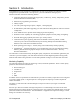
Section 2. Introduction Congratulations on your purchase of a sophisticated, yet easy-to-use aquatic environment controller. Designed with a powerful INTEL™ microprocessor, your YSI 5200 Recirculating System Monitor/Controller includes the following features: Ö Continuous monitoring of Dissolved Oxygen (DO), conductivity, salinity, temperature, pH and Oxidation Reduction Potential (ORP). Ö Menu-driven programming environment. Ö 4 Relay outputs Ö Aux.
Front Panel The front panel of the 5200 contains the display and keypad as shown in Figure 2-1 Front Panel. DO 6.57 mg/L H Cond 7.63mS * Display 5200 Hold indicator Recirculating System Monitor DO LED System Status LED Escape key DO System Status Temperature pH Conductivity ORP ESC Enter key Temperature LED pH LED ORP LED Left Arrow key Conductivity LED Right Arrow key Figure 2-1 Front Panel The YSI 5200 is operated using tactile switches mounted behind the front overlay.
Status Lights The 6 status lights located on the front panel of the 5200 (see Figure 2-1 Front Panel) indicate whether a system is operating within its preset limits or a control system has been activated.
via a digital pager. Used in conjunction with a computer running AquaManager Software, it provides email alarm notification. Feed Timer System The Feed Timer System allows control and monitoring of feedings made by the 5200. Optional Parameter control reduces the amount of food dispensed if the DO, temp or pH values are “out of range.” The optional FCR (feed conversion ratio) feature automatically increases the daily amount of food dispensed.
Section 3. Installation Installation includes the following sections: Ö Unpacking and Inspection Ö Selecting an Installation Location Ö Installing the Components Ö Mount the YSI 5200 Recirculating System Monitor Ö Installing the 5562 or 5561 Probe Assemblies Ö Wiring the System Ö Communications Method Ö Grounding Information Ö Safety Issues Ö Lightning and Surge Protection 3.1 Unpacking and Inspection Inspect the outside of the shipping carton for damage.
WARNING: To avoid severe personal injury or damage to the equipment, installation, operation and service should be performed by qualified personnel who are thoroughly familiar with the entire contents of this manual. 3.2 Selecting an Installation Location The 5200 monitor is an on-line continuous measurement tool that can be used to control various operations and provide valuable insight into the facility’s operation.
Note that this is an on-line device that is measuring actual conditions in real time. Composite sampling for pH, for example, will not match on-line monitoring. Therefore, pH values recorded by the chart recorder and/or plant control system connected to the 5200 Monitor cannot be averaged to equal the pH of a composite sample. 3.2.2 Choosing a Monitor Location The probe measures conditions in the flow stream and transmits a low voltage signal to the 5200 Monitor.
structures or near a high heat source, AC motor or transformer, radio transmitter or antenna. Be sure the monitor can be fully opened and serviced at its installed location by maintenance personnel. 3.3 Installing the Components There are three basic parts to installing the YSI 5200 Monitor, which are covered in the following sections: Ö Installing the YSI 5200 Monitor hardware and additional components Ö Installing the probe assembly Ö Wiring the 5200 Monitor 3.3.
3.3.
The following steps should be followed when wall mounting the 5200 Monitor. 1. Loosely fasten the mounting brackets (included) to the back of the 5200 Monitor with the mounting screws provided as shown in Figure 3-3. 2. Tighten the screws, securing the brackets to the Monitor. 3. Loosely fasten the 5200 Monitor to the mounting surface with the mounting screws provided as shown in Figure 3-4. 4. Tighten the screws, securing the Monitor to the surface.
3.4.2 Optional 6509 – Rail Mount Kit The 5200 Monitor can be easily mounted to pipe or handrail (1 to 1½ inch diameter) using the optional 6509 Rail Mount Kit. When using the 6509 Rail Mount Kit, the 006515 mounting flanges will have to be modified by drilling two holes to accept the u-bolts. The predrilled metal plates can be used as a template.
3.4.4 Optional 6510 – Panel Mount Kit Panel mounting the 5200 Monitor is a simple process using the 6510 Panel Mount hardware and the following tools; 5/32” Allen wrench, Philips screwdriver, and the necessary tools for cutting the mounting hole in the control panel. The 5200 Monitor may be mounted in any panel with 9.5”L x 7.5”W space available, and behind the panel depth of 5.5”.
3.5 Installing the 5562 or 5561 Probe Assemblies CAUTION: Keep pH and ORP probe tips IN A MOIST ENVIRONMENT at all times. After you have chosen suitable sites for the monitor and probe, proceed with the probe installation as described below. Avoid routing probe cabling near wiring associated with rotating machinery and/or equipment involving electrical switching or regulation.
For this type of installation, the probe guard is removed and the probe is threaded into a tee-fitting using the probe guard’s threads. All probes need to be placed into the flow stream. YSI does not provide tee fittings for this type of installation. Thread size for 5562 multiparameter probe assembly: 1.
Set Screw 2” PVC Tube Adapter Probe Guard 5562 Probe Body Stop Cap Figure 3-6 Adapter Position The following steps should be followed when mounting the 5205 or 6511 Probe Mount Kit. 1. With the 3 setscrews removed from the adapter, slide the adapter over the 5562 Probe. Align the open screw holes directly over the 3 hex bolts located on the side of the 5562 Probe. 2. Insert the setscrews so that they seat into the head of the probe’s hex bolts.
7. Slide the uncapped end of the PVC pipe up through the 2” u-bolts until there is approximately 1” of the PVC pipe above the upper mounting plate, and tighten 2” u-bolts. Note: Do not over tighten u-bolts or deformation of the PVC pipe may occur. 8. Tighten all remaining u-bolts to secure pipe. 9. Slowly slide the 5562 Probe/Adapter Assembly down the PVC pipe until it rests on the Stop Cap. 10. Connect the cable to the 5200 Monitor. 3.
Figure 3-9 Placement of Ferrites and Pluggable Sockets 3.6.1 DC Power Input Wiring 12VDC power for the 5200 Monitor may be supplied by the YSI 5578/5579 power supply accessory provided with the unit, or by a 12VDC source supplied by the user. CAUTION: The YSI 5578/5579 power supply accessory is for indoor use only, and must be connected to the 5200 Monitor with a suitable waterproof extension cable if the 5200 Monitor is installed in a damp location.
supply” or other power source which is “hazardous live” per UL 3101-1 Section 3.5.2. The 5200 Monitor may be powered by any regulated 8.5–16.5 VDC source that can provide approximately 800mA of current and is isolated from mains supply by double or reinforced insulation. (An unregulated supply may also be acceptable if the peak output voltage does not exceed 16.5VDC.
CAUTION: The sensitivity and stability of the monitor will be impaired if the monitor is not grounded. Do not apply power to the Monitor until all electrical connections are verified and secure. 3.7 Communications Method The 5200 has three methods of communication: Ö RS232 TCP/IP Serial Port—to directly connect with a computer or network Ö Modem—to communicate with a computer or pager via phone line Ö RS485 Network—to directly connect with other 5200s 3.7.
Wiring Diagram for DB-9 to RJ-45 Adapter Signal name (from 5200) RJ-45 pin # Wire color internal to adapter (may change based on supplier) TX (232TXD) 4 Red 3 RX (232RXD) 5 Green 2 Common (DGND) 6 Yellow 5 CTS (232CTS) 7 Brown 8 DTR (232DTR) 8 Gray 4 DB-9 pin # Supplied with the 5200 are a YSI# 655384 Straight-pinned Cat 5 EIA568 compliant network patch cable and pre-wired YSI# 655383 RJ-45 to DB-9 Adapter.
RJ-45 Pin RS232 Direction Number Name RS232 TCP/IP Signal Function 1 DCD I NC P Signals module that remote device is attached and powered on 2 RTS O NC P Flow control, to enable remote device to send data 3 SG P P Signal return (NOT chassis ground) 4 TXD O P P Serial data out, from YSI-5200 to remote device 5 RXD I P P Serial data in, from remote device to YSI5200 6 SG P P Signal return (NOT chassis ground) 7 CTS I NC P Flow control, to enable YSI-5200 to send data
3.8 Grounding Information This section contains important installation information regarding grounding of the 5200 Monitor. Connect earth ground to the 5200 I/O panel as described below in 3.9 Safety ISSUES. The probe is powered by the 5200 Monitor and will be operated with a “floating” ground reference. This requires that the probe not be individually grounded. Grounding the probe individually will cause a “ground loop”; i.e.
Section 4. Probe Module Probe Module covers the following: Ö Unpacking the Probe Module Ö Features of the YSI 5561 Probe Module Ö Features of the YSI 5562 Probe Module Ö Preparing the YSI 5561 Probe Module Ö Preparing the YSI 5562 Probe Module Ö Membrane Cap Installation Ö Calibration/Storage Cup (5562 only) Ö Instrument/Cable Connection Two different probe modules are available for the YSI 5200 Recirculating Monitor.
4.3 Features of the YSI 5562 Probe Module Strain Relief Metal Probe Connector Nut Cable pH/ORP Probe Dissolved Oxygen (DO) Probe Conductivity/Temperature Probe Detachable Weight Calibration/ Storage Cup Probe Sensor Guard Figure 4-2 5562 Probe Module 4.4 Preparing the YSI 5561 Probe Module To prepare the YSI 5561 Probe Module for calibration and operation, you need to install a new DO membrane cap. Refer to Section 4.6 Membrane Cap Installation for details. 4.
Figure 4-3 Port Plug Removal 3. Locate the port with the connector that corresponds to the sensor that is to be installed. The number of pins is specific for each probe type. pH or pH/ORP port Oxygen port Conductivity/Temperature port Figure 4-4 Sensor Port Identification 4. Apply a thin coat of o-ring lubricant (supplied in the YSI 5511 maintenance kit) to the o-rings on the connector side of the sensor (see Figure 4-5 O-Ring Lubrication).
CAUTION: Do not cross thread the sensor nut. Tighten the nut until it is flush with the face of the probe module bulkhead. Do not over tighten. Figure 4-7 Bulkhead Seating 7. Repeat steps 3-6 for any other sensors. 8. Replace the probe sensor guard. Dissolved Oxygen Sensor Installation The YSI 5562 comes with the DO sensor already installed. Refer to Section 11.4.2 DO Sensor Replacement for instructions on installing the YSI 558 Replaceable DO Module Kit. 4.
CAUTION: Do not touch the membrane surface. 8. Screw the membrane cap onto the sensor moderately tight. A small amount of electrolyte should overflow. 9. IMPORTANT: To prevent the formation of a bulge in the membrane (which can slow sensor response), partially unscrew the membrane cap then retighten. 10. Screw the probe sensor guard on moderately tight. 4.7 Calibration/Storage Cup (5562 only) The YSI 5562 Probe module is supplied with a convenient calibration/storage cup.
Probe Connector Figure 4-10 Bottom Connectors 2. Holding the cable firmly against the cable connector, turn the locking mechanism clockwise until it snaps into place. 3. Remove the cable from the instrument by turning the cable connector counterclockwise until the cable disengages from the instrument.
Section 5. Operation Operation covers the basic set up and operation of the 5200 Recirculating Monitor including: Ö Ö Ö Ö Ö Run Screen Main Menu Parameters Menu Daily Checks System Test See Section 9 Advanced Setup for more advanced set up options. In the Parameters menu section, Temperature is explained in step-by-step detail as an example. Once familiar with the temperature set up procedure, other parameters can be set up in a similar manner. 5.1 Run Screen The initial 5200 display is the Run screen.
Indicates temperature compensation Cond 24.0mS * Sal. 10.4ppt The status LEDs show the current status of each parameter as follows: OFF – parameter not enabled GREEN – normal range FLASHING GREEN – control mode (turns off when it crosses the original set point) RED – alarm (turned off by pressing any key, except escape, and resolving the alarm condition) 5.
5.3 Parameters Menu The Parameters Menu allows you to enter the menu for specific measurement parameters. In addition to establishing Set Points, Control Points and Alarms, the Parameters menu also enables the user to perform calibrations (refer to Section 6 Calibration for calibration routines). The majority of the day-to-day operations of the YSI 5200 will be accessed through this menu.
Low Alarm ON Low Alarm Setpoint Acceptable Operating Range Low Control ON Low Control Setpoint ON Optimal Setpoint Value Hi Control ON High Control Setpoint ON High Alarm ON High Alarm Setpoint Figure 5-3 Setpoints and Ranges When these values are entered, the system will operate as illustrated in Figure 5-3. As long as the water quality parameters remain within the acceptable operating range, no control or alarm will be activated.
Parameter Set Point High Set Point #1 High Set Point #2 Low Set Point #1 Low Set Point #2 High Alarm Low Alarm ORP +400 mV +425 mV --- +375 mV --- +435 mV +300 mV Temperature 25 C or 77 F 26 C or o 78.8 F --- 24 C or o 75.2 F --- 26.5 C or o 79.7 F o 23.5 C or o 74.3 F pH 7.00 7.50 --- 6.50 --- 8.00 6.00 Specific Conductance (0-200 us) 160.0 us (0-200 us) 180.0 us --- (0-200 us) 140.0 us --- (0-200 us) 190.0 us (0-200 us) 130.
Temp Menu NO Enabled Yes Setup Menu Set Point Menu Control Menu Alarm System Set Point 0-45 C Range Low Select Relay Range Low From 0.0 to 0.1 below Set Point Range High Select Relay Range High From Set Point + 0.1 to Max Alarm Low Select Relay Alarm High Select Relay Alarm Low Alarm High F Accept C Accept From 0.0 to 0.1 below Range Low From Range High + 0.
Set Point Menu Enter to Select Press the Enter [ ] key. Enter to Select SetPoint Set Point Menu selections for Temperature are SetPoint, Range Low, Range High, Alarm Low and Alarm High. SetPoint The Temperature Set Point defines the optimum Temperature that you wish the YSI 5200 to maintain in the aquatic environment. This determines the control range for heating and chilling devices. See Section 5.3.1 Entering Setpoint and Range Values for an overview of control functions.
Range High From the Set Point menu (with the Range High option displayed), press the Enter [ ] key. Range High 078.8°F Using the [e], [f] and Enter [ ] keys, enter the Range High value. NOTE: The Range High value must be higher than the Set Point. Range High 074.0°F Press the Enter [ ] key. The display returns to the Set Point Menu. Enter to Select Range High Press the [f] key for the next Set Point selection, Alarm Low.
Enter to Select Alarm High NOTE: You may enter the other Temperature System menu options (Control Menu, Alarms System and Calibration), but your changes are not saved until you exit the Temp System menu as described below. Press the [ESC] key two times to exit the Temp System menu. You will be prompted to save your changes. Set Point Menu Save? Yes Press the Enter [ ] key to save the changes, or press the [e] or [f] key to select No, then press the Enter [ ] key to exit without saving any changes.
Range Low menu selections are Relay Disabled, Relay Internal and Relay SubNet. NOTE: Range High, Alarm Low and Alarm High menus have these same selections. Relay Disabled Relay Disabled is the default setting. It prevents the Range Low control point from triggering any relays (Internal or SubNet). To select this option, press the [ESC] key to return to the Control Menu.
Press the Enter [ ] key to save the changes, or press the [e] or [f] key to select No, then press the Enter [ ] key to exit without saving any changes. NOTE: Use the same procedure as described above to set up a relay to be triggered by Range High, Alarm Low or Alarm High. Relay SubNet This function is for future expansion and is not yet available. Set the Range Low control to trigger an external subnet relay (connected to this 5200 via the RS485 network).
Changing the temperature scale automatically recomputes your Set Points. For example, if your Set Points were entered in Fahrenheit and you change the temperature scale to Celsius, all of your Set Points will be automatically converted to their Celsius equivalents. Select the temperature scale as follows: From the Temp System menu, press the [e] or [f] key until the Setup Menu option appears. Setup Menu Enter to Select Press the Enter [ ] key. Temp Scale Enter to Select Press the Enter [ ] key.
5.3.3 DO System DO System menu selections are shown below. DO Menu NO Enabled Gray menus only available with Display Range set to Manual mode and Interval set to Continuous. Yes Setup Menu Calibration Set Point Menu Control Menu Alarm System Enable System (Yes/No) Set Point Set Point Value Range 1 Low From Min to .
NOTE: Set Point, Control and Alarm System Menus are only available when a Manual Display Range is selected (see Section 5.3.3 DO System, Setup Menu, Display Range) and the DO Interval is set to Off (DO is on continuously). See Section 5.3.3 DO System, Setup Menu, Interval. NOTE: DO readings are still compensated for salinity changes even if conductivity is disabled. Calibration Calibration is covered in Section 6 Calibration. DO can be calibrated in either % saturation (recommended) or mg/L. See Section 6.
Alarm System The alarm system for each measurement parameter can be turned on or off. When on, an audible alarm will sound on the YSI 5200 and an alarm page will be sent (if a modem is installed and paging is enabled). The alarm will remain on until a key is pressed. See 7.1 Alarm Logic Flow Charts for details. Setup Menu DO Setup Menu selections are shown below.
seconds of the powered cycle. The entire cycle is then repeated. Interval mode extends the time between probe servicing and calibration, but disables DO control and alarm functions. Display Range The 5200’s DO system operates in either an Auto or Manual Range. Use Manual to enable the 5200’s control and alarm functions. If you select Auto, the control/alarm options are NOT available. CAUTION: Changing the display range will cause the DO alarm and control set points to change.
5.3.4 pH System pH System menu selections are shown below. pH Menu No Enabled Yes Calibration Set Point Menu Control Menu Set Point Set Point Value Range Low From Min to .01 below Set Point Range High From Set Point + 0.01 to Max Dose Up At Specific Value for XX MIN Dose Up Wait XX MIN Dose Down At Specific Value for XX Sec Dose Dpwn Wait XX MIN Alarm Low From Min to 0.1 below Range Low Alarm High From Range High + .
Calibration Calibration is covered in Section 6 Calibration. pH can be calibrated at either one point or two points. See Section 6.2.4 pH Calibration for details. Set Point Menu The YSI 5200 can control pH by dosing a buffer solution , injecting CO2 gas or both. pH control can operate in two different ways. It can operate the same as most other 5200 control systems—when the parameter value reaches the low or high range setpoint, control is activated until the value returns to the optimal setpoint.
target operating range, it will turn on the pH doser or CO2 injector until the pH returns to the optimal Set Point value. Control Menu After entering the pH set point and ranges, use the Control Menu to select which relay each range or alarm will activate. Alarm System The alarm system for each measurement parameter can be turned on or off. When on, an audible alarm will sound on the YSI 5200 and an alarm page will be sent (if a modem is installed and paging is enabled).
5.3.5 ORP System ORP System menu selections are shown below. ORPMenu No Enabled Yes Calibration Set Point Menu Control Menu Alarm System Enable System (Yes/No) Display Actual Value " " Current Temp Value Scrolling Text* Set Point Range Low Set Point Value Range Low Select Relay Range High Select Relay Alarm Low Select Relay Alarm High Select Relay From Min to .01 below Set Point Get UserValue Range High From Set Point + .01 to Max Alarm Low From Min to .
Calibration Calibration is covered in Section 6 Calibration. See Section 6.2.5 ORP Calibration for details. Set Point Menu The ORP level can be used as an indicator of ozone. Acceptable levels are between 0 and 450 mV. The ORP Set Point can be maintained through the use of an ozonizer in a monitoring and control system. The Set Point can be established anywhere from –999 to +999 mV. For controlling applications you will also need to establish the Low and High control values and alarm values.
5.3.6 Conductivity System Conductivity System menu selections are shown below. Conductivity Menu No Enabled Gray menus only available with Display Range set to Manual mode. Yes Setup Menu Calibration Set Point Menu Set Point Set Point Value Range Low From Min to .01 below Set Point Range High From Set Point + 0.
NOTE: Set Point, Control and Alarm System Menus are only available when a Manual Display Range is selected. See Section 5.3.6 Conductivity System, Setup Menu, Display Range. Calibration Calibration is covered in Section 6 Calibration. See Section 6.2.3 Conductivity Calibration for details. Set Point Menu Conductivity control, like pH, can operate in two different ways.
Set the Dose Down to 0 to select normal conductivity control (see Section 5.3.6 Conductivity System, Set Point Menu) where the YSI 5200 will start dosing when the conductivity level reaches the high end of the target operating range and will keep dosing until it reaches the optimal set point. Dose Down Wait Dose Down Wait (in minutes), or dwell time, is the length of time that the YSI 5200 will wait until dosing can occur again.
Display Range The 5200’s Conductivity system operates in either Auto ranging or 1 of 4 manual ranges. Use a manual range to enable the 5200’s control and alarm functions. If you select Auto, the control/alarm options are NOT available. CAUTION: Changing the display range will cause the Conductivity alarm and control set points to change. After changing the display range, confirm all set point values.
8. Clean the sensors every 30–90 days, or as needed. A screen prompt on the YSI 5200 display will remind you to do so. See 9.1.1 Service, Clean Probes. 5.5 Conducting a System Test When you conduct a System Test, all built-in relays automatically go to an "off" condition. Once in the System Test mode, you can select any relay and manually turn it on or off. The purpose of this test is to make sure each relay is working correctly.
9. Press the Enter [ ] key to change the state of the relay to On. R 1 R 2 R 3 R 4 Off On Off Off 10. After you have finished testing this relay system, press the Enter [ ] key. The state of the relay will flash. R 1 R 2 R 3 R 4 Off On Off Off 11. Press the [e] or [f] key to select Off. R 1 R 2 R 3 R 4 Off Off Off Off 12. Press the Enter [ ] key to turn the relay Off. R 1 R 2 R 3 R 4 Off Off Off Off 13. Repeat Steps 6–12 for any other relays you would like to test. 14.
Section 6. Calibration All of the sensors, except temperature, require periodic calibration to assure high performance. You will find specific calibration procedures for all sensors that require calibration in the following sections. If a sensor listed is not installed in your probe module, skip that section and proceed to the next sensor until the calibration is complete. CAUTION: Reagents that are used to calibrate and check this instrument may be hazardous to your health.
Ö If you are using laboratory glassware for calibration, you do not need to remove the probe sensor guard to rinse and dry the sensors between calibration solutions. The inaccuracy resulting from simply rinsing the sensor compartment and drying the outside of the guard is minimal. Ö If you are using laboratory glassware, remove the stainless steel weight from the bottom of the YSI 5562 Probe Module sensor guard by turning the weight counterclockwise.
6.2 Calibration Procedures 6.2.1 Accessing the Calibrate Screen 1. From the Run screen, press the Enter [ ] key, then the [e] or [f] key until the Parameters option appears. Parameters Enter to Select 2. Press the Enter [ ] key to select Parameters. DO System Enter to Select 3. Press the [e] or [f] key until the parameter you want to calibrate appears. Conductivity is used as an example below. Cond System Enter to Select 4. Press the Enter [ ] key to display the Enabled screen.
6.2.2 Dissolved Oxygen Calibration This procedure calibrates dissolved oxygen. Calibrating any one option (% or mg/L) automatically calibrates the other. Calibration If Cond turned Off Display Question Yes Salininty 0-45ppt No %Sat mg/L Alt 100 X 100 Ft Display Actual Value mg/L Scrolling Text*2 Display Actual Value % (CAL Value via Math) Scrolling Text*1 Get UserValue Calibration Complete Calibration Complete Figure 6-1 DO Calibration Menu DO Calibration in % Saturation 1.
Salinity 30 ppt NOTE: The instrument must be on for at least 20 minutes to polarize the DO sensor before calibrating. % SAT Enter to Select 3. Select % Saturation. 4. Place approximately 3 mm (1/8 inch) of water in the bottom of the calibration/storage cup. 5. Place the probe module into the calibration/storage cup. NOTE: Make sure that the DO and temperature sensors are not immersed in the water. 6.
2. If your probe module contains a conductivity probe and it is Enabled, skip to Step 3. If your probe module does not contain a conductivity probe (or the conductivity probe is not Enabled), enter the salinity of the sample stream. Salinity 30 ppt NOTE: The instrument must be on for at least 20 minutes to polarize the DO sensor before calibrating. % Sat Enter to Select 3. Press the [e] or [f] key to select mg/L. mg/L Enter to Select 4. Press the Enter [ ] key.
6.2.3 Conductivity Calibration This procedure calibrates conductivity and salinity. Note that the 5200 is calibrated at the factory and, with proper sensor maintenance, calibration is rarely required. However, from time to time it is wise to check the conductivity calibration and recalibrate when necessary. Calibration Display Actual Value " " Current Temp Value Scrolling Text* G et UserValue Calibration Complete Figure 6-2 Conductivity Calibration Menu 1.
NOTE: The sensor must be completely immersed past its vent hole. Using the recommended volumes from Table 6-1 Calibration Volumes, should ensure that the vent hole is covered. 5. Screw the calibration/storage cup on the threaded end of the probe module and securely tighten. NOTE: Do not over tighten as this could cause damage to the threaded portions. 6. Allow at least one minute for temperature equilibration before proceeding. 7. Observe the Conductivity and Temperature readings.
6.2.4 pH Calibration Calibration 1 Point 2 Point Display Actual Value " " Current Temp Value Scrolling Text* Display Actual Value " " Current Temp Value Scrolling Text* Display Actual Value " " Current Temp Value Scrolling Text* Get UserValue Calibration Complete Figure 6-4 pH Calibration Menu 1. Go to the pH calibrate screen as described in Section 6.2.1 Accessing the Calibrate Screen. Enter to Select 1-Point 2. Select either One-Point or Two-Point calibration.
one-point calibration. The procedure for this calibration is the same as for a 2-point calibration, but the software will prompt you to select only one pH buffer. Ö Select the 2-point option to calibrate the pH sensor using two calibration standards. Use two standards that cover the pH range of your samples. For example, if the pH of a pond is known to vary between 5.5 and 7, perform a two-point calibration with pH 7 and pH 4 buffers. 3.
12. Press the Enter [ ] key to enter the value. The display will notify you that this is Pass(2), then the pH Entry screen is displayed. Pass 2 pH= 7.04 T= 73.5° Wait til Stable 13. Repeat steps 4 through 10 above (pass 2) using a second pH buffer. 14. Press the Enter [ ] key to enter the value. After displaying a brief message, the display will return to the pH Calibration menu. Calibration Complete Calibration Two-Point 15. Press the [ESC] key to exit the pH Calibration menu.
6.2.5 ORP Calibration Calibration Display Actual Value " " Current T emp Value Scrolling T ext* G et UserValue Calibration Complete 1. Go to the ORP calibrate screen as described in Section 6.2.1 Accessing the Calibrate Screen. -703mv T=72.5°C Wait til Stable 2. Place the correct amount (see Table 6-1 Calibration Volumes) of a known ORP solution (we recommend Zobell solution) into a clean, dry or pre-rinsed calibration/storage cup. WARNING: Calibration reagents may be hazardous to your health.
-703mv T=72.5°C User Val +307 8. Enter the correct value of the calibration solution you are using at the current temperature. Refer to Table 6-2 Zobell Solution Values. Temperature °C Zobell Solution Value, mV -5 270.0 0 263.5 5 257.0 10 250.5 15 244.0 20 237.5 25 231.0 30 224.5 35 218.0 40 211.5 45 205.0 50 198.5 Table 6-2 Zobell Solution Values 9. After displaying a brief message, the display will return to the ORP Calibration menu.
Section 7. Alarm/Pager 7.
Em ail No Stop Em ail Paging I s Autopoller running Yes No Stop Is Autopoller flag for this node set Yes No Stop Is "Enable Em ail Alarm Page System " checked in Autopoller Yes Stop Are "Alarm Detection" & "Em ail on Alarm " checked in AquaManager No Yes W ait 60 seconds m inim um plus node ping tim e Send Em ail Stop YSI Incorporated Yes Has Alarm been cleared 74 No W ait for Pager Retransm it tim e 5200 Recirculating System Monitor
Power Source Stop No Power Alarm Has power source changed Yes Yes Is Gerneral Alarm enabled Activate General Alarm relay No Activate Red LED and display m essage Is Pager enabled Yes Send Page No Is em ail notification enabled Yes Em ail No W ait for Pager Retransm it tim e No Has power been restored Yes Send Power Good Page Stop YSI Incorporated 75 5200 Recirculating System Monitor
Auxiliary Alarm ing (digital m ode only) Auxiliary state Stop No Is Auxiliary state = alarm state Yes Is Alarm holdoff tim e set to zero No Count down holdoff tim e for this Auxiliary Input Yes Is Gerneral Alarm enabled Yes Activate General Alarm relay No Activate beeper and display m essage Is Pager enabled Yes Send Page No Em ail YSI Incorporated 76 5200 Recirculating System Monitor
7.2 General Alarm Temperature Alarm DO Alarm pH Alarm General Alarm Alarm Light or Buzzer ORP Alarm Conductivity Alarm Auxiliary Alarm The General Alarm is a Summary alarm that activates a single device, such as a light or buzzer, whenever any one of the individual parameter alarms is triggered. If the value of a parameter reaches the alarm low or high point and the Alarm Hold Off time (See Section 9.2.3 Alarm Hold Off) has expired, an alarm occurs.
Section 8. Network Multiple 5200 Recirculating Monitors can be connected together via their RS485 network ports (see 8.1 RS485 Network). Each network (group of connected 5200s) consists of 1 Master unit and up to 31 Slave units. The default network Mode setting is Master. NOTE: Each Slave in the network must have a unique Sub Address. 8.1 RS485 Network The 5200’s optically isolated RS485 interface is located on the upper right hand corner of the I/O plate.
Wire Solid Blue Wire White w/Blue Stripe Solid Orange Wire White w/Orange Stripe Terminal 1 2 3 4 Connection T (-) T (+) R (-) R (+) NOTE: On the final slave in a string, install one 120Ω (ohm) resistor between T(+) and T(-) and one 120Ω (ohm) resistor between R(+) and R(-). Resistors are included with each 5200.
2. Connect the switch to Auxiliary Input #1 or Auxiliary Input #2 using the 3-pole YSI 065942UL Pluggable Socket Connector. See Figure 8-1. Connect one wire to the ground (GND) terminal and the other to the In 1 or In 2 terminal. NOTE: When connecting a switch to Auxiliary Input #2, set the input to Digital mode. See Section 9.4.2 Input #2. IN 2 -- GND-- IN 1 -- 3. Set the 5200 to either Alarm on Open or to Alarm on Closed, depending on the type of switch used. See Section 9.4.1 Input #1, Control.
IN 2 -- GND-- IN 1 -- IN 2 -- GND-- IN 1 -- Figure 8-2 Analog Instrument Connection YSI Incorporated 81 5200 Recirculating System Monitor
Section 9. Advanced Setup Advanced Setup includes: Ö System Menu Ö Timers Menu Ö Relay Output Wiring 9.
System Menu Data Locale Service Communications Display Address Password General Alarm Set Date MM/DD/YYYY Set Time HH:MM:SS Display DownLoader Yes/No No Enabled Locale USA/Intl Display Speed 1-20 Display Mode Normal/Inverse Yes Data Logger Set Interval 1-3600 minutes Clear Data Entire Log Continue Y/N Set Password XXXXXXXXXXXX No Print Data Log Events Enabled Entire Log Yes/No Current Log Select Relay Figure 9-1 Systems Menu YSI Incorporated 83 5200 Recirculating System
9.1.1 Service Service menu selections are shown below. Service Menu System Test Reset To Factory Clean Probes Yes/No No R1 On/Off Enabled R2 On/Off Yes R3 R4 On/Off Duration 0-180 Days Reset Yes/No On/Off Figure 9-2 Service Menu Clean Probes This feature reminds the user when it is time to clean the probes by scrolling a text message across the display.
Reset After the set number of days has passed and the Clean Probes message appears on the display, it must be reset. Reset to Factory CAUTION: Reset to Factory returns all the settings to the factory default values (see Section 16 Factory Default Settings). All calibration values, alarms, set point values and control functions will be lost. If you are sure you want to return to the factory settings, proceed as follows: System Test Use System Test to verify that each control system is working correctly.
9.1.2 Communications Communications menu selections are shown below.
Alarm Logic Flow Charts). After the Alarm Hold Off period expires, the audible alarm (a standard feature) will activate. If the 5200 is configured and enabled for alarm pager support, an alarm page will be sent indicating which parameter is in alarm state (pH, ORP, Temperature, etc.) and the type of alarm it is (high alarm, low alarm, etc.). This information is transmitted via modem (the 5200’s modem or a computer running AquaManager software and equipped with a compatible modem) to your pager.
Dial Modifier Description , Delay for approx. 1 second W Wait for dial tone The ‘W’ dial modifier is particularly important to make sure that there is a “dial tone” before initiating a page. Pager Phone Number Example The following is an example of one scenario where the pager number requires a bit more than the phone number: To reach the pager, it is necessary to: • • • • Dial 9 for an outside line. Wait for the dial tone. Dial the paging company.
Page Now Page Now sends a test page consisting of the last 3 digits of the serial number of the 5200 followed by 999. As an example, for a YSI 5200 with serial number 52-003598, the page would appear as follows: “598 999” Serial Setting The only Serial Setting selection is Baud Rate. Baud Rate The baud rate is the speed that the YSI 5200 transmits data via the serial IP port. It can be set at 300, 1200, 2400, 9600 or 19,200 baud.
5. After the download is complete, run the file (that you just downloaded) and follow the on screen instructions to install the YSI 5200 Code Updater on your computer. If you encounter difficulties, contact YSI customer service for advice. Refer to Section 14 Warranty and Service Information. 6. Connect the YSI 5200 to a serial port of your computer using the YSI 655384 Network Cable and YSI 655383 RJ-45 to DB-9 Adapter (or YSI 5285 Opto-isolator). NOTE: The 5200 must be on and displaying the Run screen.
12. Disconnect power from the 5200. 13. Reapply power to the 5200. 9.1.6 General Alarm See Section 7.2 General Alarm for a detailed description. 9.1.7 Display Address (Serial Number) Displays the Address (serial number) of the 5200 on the screen. The Address and software version are also displayed whenever the 5200 is powered on. 9.1.8 Data The 5200 has a 32K volatile memory, allowing it to log 750 sample data sets. The logging rate is user selectable.
Log Events The 5200 can Log Events performed, such as a control system, alarm, or timer turning on or off. YSI AquaManager software is required to display logged events. 9.1.9 Locale The YSI 5200 is equipped with an internal clock/calendar with its own backup battery. The clock/calendar is set from the factory, but you may need to adjust it to your time zone.
9.
9.2.1 Feed Timer The Feed Timer System allows control and monitoring of feedings made by the 5200. Optional Parameter control reduces the amount of food dispensed if the DO, temp or pH values are “out of range.” Feed Timer parameter controls work independently of the 5200 parameter setpoint menus and operation. The optional FCR (feed conversion ratio) feature automatically increases the daily amount of food dispensed.
Feed Timer No Enabled Yes Setup Test Calibrate Feeder only available when a relay is enabled Feeder Feed Days SMTWTFS FCR Parameter Setup Menu Calibrate Feeder Enabled Enabled Time Elapsed Biomass DO Low Measured Weight Feed % Biomass DO High Daily Weight DO Change Relay Select Relay FCR Factor Temp Low Units Oz,lb,g,kg Start Date End Date Feed Mode Timed/ Continuous Temp High Start Time Temp Change End Time pH Low Start Time and End Time only available when Feed Mode is T
Feeder Prior to operating the feed timer system, the following fields must be configured: Ö Feed Days—days of the week feedings will occur Ö Start and End Dates—dates within which the feed timer system will operate Ö Feed Mode—feed cycle type (timed or continuous) Ö Daily Feed Amount—daily weight of food to be dispensed Ö Daily Feedings—number of feedings to occur per feeding cycle Feed Days Select the days of the week that feeding(s) should occur.
Select Cont. (Continuous) if feedings are to occur over the entire day. Once a Continuous feed configuration has been configured, the 5200 determines any remaining feeds for the 24 hour period, ending at 23:59. In continuous feed mode the feed cycle always begins at 00:00 (midnight). Start and End time fields are not available options for Continuous feed mode. Start Time Select the time the 1st feeding should occur (in 24 hour format).
Day1 Day 2 Day 3 Day 4 Day 5 Day 6 Day 7 1000 1020 1040 1061 1082 1104 1126 3% 3% 3% 3% 3% 3% 3% Daily Feed Amount 30 30.6 31.2 31.8 32.5 33.1 33.8 FCR Factor 1.5 1.5 1.5 1.5 1.5 1.5 1.5 1/FCR x Feed Amount 20 20.4 20.8 21.2 21.6 22.1 22.5 1020 1040 1061 1082 1104 1126 1149 Biomass Feed % (of) Biomass New Biomass Parameter Changes in water parameter conditions will affect the amount of food fish eat and thus will affect fish growth.
Measured Weight Weigh the amount of food dispensed and enter the value at the Measured Weight screen. Digits to the left of the blinking cursor cannot be changed. If an incorrect value is entered, another test will have to be performed. NOTE: Since feeders and food size vary, run several tests and enter the average weight. If food lot or size is changed, be sure to recalibrate the feeder. Press Esc and enter “Yes” to save the value, or “No” to cancel and perform another calibration/test.
NOTE: Allow enough time to clean the probes or provide tank maintenance without breaching any control or alarm conditions. 9.2.3 Alarm Hold Off The Alarm Hold Off timer prevents any system parameter (DO, pH, etc.) from generating an alarm or page until the hold off time has expired. NOTE: The Auxiliary Inputs each have separate Hold Off timers. See Section 9.4.1 Input #1, Hold Off. 9.2.4 Timers 1–4 Use Timers 1–4 to control external devices, such as a lighting system.
9.3.1 Example—Wiring a Contactor The 5200’s internal relays are not intended to switch heavy loads above the current rating of the relay (see Section 15 System Specifications for relay specifications). Heavy loads require installing a separate external relay (contactor) between the 5200 and the load. Figure 9-8 shows a typical connection of the 5200 and a load using a contactor. NOTE: Make sure that the contactor meets the electrical requirements of the load. N.O.-- N.C.-- COM-- 4 N.O.-- N.C.
9.4 Auxiliary System The YSI 5200 has two auxiliary inputs. Use digital inputs for control, and to trigger alarms and paging (see 7.1 Alarm Logic Flow Charts). A selectable wait period (Hold Off) prevents false control or alarms. Auxiliary System Menu selections are shown below. Aux Menu Input #1 Input #2 Enable System Enable System No No Yes Yes Control Alarms Hold Off Relay Control on Open or Closed Digital Digital/User Def. User Def.
9.4.1 Input #1 Input #1 is a digital only input, triggered by either a switch open or a switch closed condition. Control Select Close to trigger the input when the contacts of an external switch close. Select Open to trigger the input when the contacts of an external switch open. Hold Off Hold Off is the number of seconds that the 5200 will wait before activating a control relay or generating an alarm. The hold off time is selectable from 0 to 255 seconds.
User Def. Set Point Menu Alarm System Min/Max Values Scale Alarm Low Alarm High Alarm Low -5000 to +5000 Alarm High -5000 to +5000 Alarms Hold Off Enabled Yes/No Seconds 000 to 255 Min Max Min -5000 to +5000 Max -5000 to +5000 Range Format 0-1V 0-5V 4/20mA 0 0.0 0.
Alarm System The alarm system can be turned on or off. When on, an audible alarm will sound on the YSI 5200 and an alarm page will be sent (if paging is enabled). The alarm will remain on until a key is pressed. See 7.1 Alarm Logic Flow Charts for details. Hold Off Hold Off is the number of seconds that the 5200 will wait before activating a control relay or generating an alarm. The hold off time is selectable from 0 to 255 seconds Relay Relay Disabled Relay Disabled is the default setting.
Section 10. AquaManager Software AquaManager is a 32-bit Windows® application that provides remote access and network management services between a PC and the YSI 5200 Recirculating Monitor. The function of the software is to assist users with the complex task of monitoring local or remotely-connected YSI 5200 Recirculating Monitor units. AquaManager has three methods of communicating with YSI 5200s.
Section 11. Maintenance It is important to remember that the quality of data obtained will be heavily dependent on three factors directly related to the probe: Ö Proper attention to detail of and general maintenance at the physical deployment site of your probe. Ö A well-defined quality assurance program that is carried out on a regular basis to assure that the sensors are performing properly. Ö Proper periodic calibration and maintenance of the specific sensors.
11.2 Calibration Checks The sensors are of high quality and should exhibit excellent performance in your application in excess of the warranty period. However, the dissolved oxygen, pH, ORP and conductivity sensors will inevitably show some drift during deployment due to natural chemical changes to the reagents in the probes, physical changes of the electrodes, minor fouling of the sensor surfaces, or all of these factors.
10. (5562 Probe only) Activate the 2-point pH calibration protocol from the 5200 display and recalibrate the instrument using the two buffers as described in Section 6.2.4 pH Calibration. 11. Rinse the probe with water and place in the calibration/storage cap containing about 1/8 inch (3 mm) of water. Make sure that the dissolved oxygen sensor is not immersed in the water. 12.
11.4 Sensor Care and Maintenance Once the sensors have been properly installed, remember that periodic cleaning and DO membrane changes are required. 11.4.1 DO Sensor The YSI polarographic dissolved oxygen probe is a Clark-type sensor in which the reduction of oxygen at the gold cathode is accompanied by a corresponding oxidation of a silver anode to silver chloride (AgCl).
Chemical Cleaning: Remove the membrane cap and soak the entire anode section in a 14% ammonium hydroxide solution for 2 to 3 minutes, followed by a thorough rinsing with clean water. The anode should then be thoroughly wiped with a wet paper towel to remove the residual layer from the anode. Mechanical Cleaning: Sand off the dark layer from the silver anode with 400 grit wet/dry sandpaper. Wrap the sandpaper around the anode and twist the sensor.
Probe Guard DO Sensor Set Screw Cable End Hex Key Wrench Figure 11-2 5561 Probe Module - DO Sensor Replacement 2. Insert the long end of the hex key wrench into the small hole in the side of the probe module bulkhead. Turn the wrench counterclockwise and remove the screw. (You do not have to remove the screw all the way to release the sensor.) 3. Pull the old DO sensor module straight out of the probe module body. NOTE: The DO sensor is not threaded, it is keyed, so it cannot be removed by twisting. 4.
CAUTION: When using a cotton swab with the YSI 5564 or YSI 5565, be careful NOT to wedge the swab tip between the guard and the glass sensor. If necessary, remove cotton from the swab tip, so that the cotton can reach all parts of the sensor tip without stress. NOTE: If good pH and/or ORP response is not restored by the above procedure, perform the following additional procedure: 1. Soak the sensor for 10-15 minutes in clean water containing a few drops of commercial dishwashing liquid. 2.
3. After cleaning, check the response and accuracy of the conductivity cell with a calibration standard. NOTE: If this procedure is unsuccessful, or if sensor performance is impaired, it may be necessary to return the sensor to a YSI authorized service center for service, Refer to Section 14 WARRANTY AND SERVICE INFORMATION. The temperature portion of the sensor requires no maintenance. 11.5 Recommended cleaning of the 5200 Monitor and Accessories Clean the 5200 Monitor and accessories as needed.
Section 12. Storage Proper storage between periods of usage will not only extend the life of the sensors, but will also ensure that the unit will be ready to use as quickly as possible in your next application. 12.1 Short Term Storage No matter what sensors are installed in the instrument, it is important to keep them moist without actually immersing them in liquid. Immersing them could cause some of them to drift or result in a shorter lifetime.
rehydrated by soaking the sensor for several hours (overnight is recommended) in a solution which is 2 molar potassium chloride. If potassium chloride solution is not available, soaking the sensor in tap water or commercial pH buffers may restore sensor function. However in some cases the sensor may have been irreparably damaged by the dehydration and will require replacement. CAUTION: Do not store the sensor in distilled or deionized water as the glass sensor may be damaged by exposure to this medium. 1.
Section 13. Troubleshooting The following table describes problems you may encounter when using the YSI 5200 Recirculating Monitor and provides suggestions to overcome the symptom. Problem Possible Solution Display Problems No display Check power supply. Remove power (primary and back-up) for 30 seconds then reapply power. Instrument software appears to be locked up as evidenced by no response to keypad entries or the display not changing.
Problem Possible Solution Sensor Problems pH or ORP readings are unstable or inaccurate. Out of Range message appears during calibration. Sensor requires cleaning. Follow sensor cleaning procedure. Sensor requires calibration. Follow cal procedures. pH sensor reference junction has dried out from improper storage. Soak sensor overnight in 2 molar potassium chloride. If not available, tap water or pH buffer may be substituted. Water in sensor connector. Dry connector; reinstall sensor.
Range Low In Use (120) Only one parameter can control each relay. In order to use this relay, you must first enter the General Alarm menu and assign a different relay to the General Alarm.
Section 14. Warranty and Service Information This YSI 5200 Recirculating Monitor ("YSI 5200") is warranted by YSI for two years from date of purchase by the end user who first places the YSI 5200 into operation ("First End User") against defects in materials and workmanship (excluding components and materials for the YSI 5200 which are separately warranted below).
U. S. Service Centers Ohio YSI Incorporated • Repair Center • 1725 Brannum Lane • Yellow Springs, Ohio • 45387 • Phone: (800) 765-4974 • (937) 767-7241• E-Mail: info@ysi.com Florida Aquatic Eco Systems, Inc. • 1767 Benbow Court • Apopka, Florida • Phone: (407) 886-3939 • Fax: (407) 886-6787 Cleaning Instructions NOTE: Before they can be serviced, equipment exposed to biological, radioactive, or toxic materials must be cleaned and disinfected.
YSI Incorporated 122 5200 Recirculating System Monitor
Section 15. System Specifications Temperature Sensor type 10,000 ohm @ 25°C YSI Precision™ thermistor Range 0 to 45°C 32 to 113oF Accuracy ± 0.2 °C Resolution 0.1°C Dissolved Oxygen Sensor type Membrane covered steady state polarographic Range 0 to 500% air saturation 0 to 60 mg/L Accuracy ±2% or ±0.2 mg/L, whichever is greater (0–200%) ±6% of reading (200–500%) Resolution 0.1% or 0.01 mg/L (0–10 mg/L) 1% or 0.1 mg/L (10–60 mg/L) Response time 98% of reading in 5 minutes pH Range 0.
Salinity Sensor type calculation from temperature and conductivity Range 0 to 80 ppt Accuracy ±2% or ±0.1 ppt Resolution 0.1 ppt Power Requirements (DC operation) Nominal 12 VDC Operating Range 8.5 to 16.5 VDC (below 8.5 VDC reverts to optional battery back up) Operating Current 500–800 mA Depending on mode of operation Control Output Relays Type SPDT Maximum Current 5 amp Maximum Voltage 125 VAC Frequency 50/60 HZ Auxiliary Inputs Type 1 analog (0 to 1.0 VDC, 0 to 5.
Section 16.
Setting Conductivity Alarms Parameters—DO DO DO Interval DO Range DO Units DO Membrane Type DO Set Point DO High Control #1 DO High Control #1 Relay DO High Control #2 DO High Control #2 Relay DO Low Control #1 DO Low Control #1 Relay DO Low Control #2 DO Low Control #2 Relay DO High Alarm DO High Alarm Relay DO Low Alarm DO Low Alarm Relay DO Alarms Parameters—ORP ORP ORP Set Point ORP High Control ORP High Control Relay ORP Low Control ORP Low Control Relay ORP High Alarm ORP High Alarm Relay ORP Low Alar
Setting pH Low Control Relay pH High Alarm pH High Alarm Relay pH Low Alarm pH Low Alarm Relay pH Dose Up Time pH Dose Up Wait pH Dose Down Time pH Dose Down Wait pH Alarms Parameters—Salinity Salinity Parameters—Temperature Temperature Temperature Set Point Temperature High Control Temperature High Control Relay Temperature Low Control Temperature Low Control Relay Temperature High Alarm Temperature High Alarm Relay Temperature Low Alarm Temperature Low Alarm Relay Temperature Units Temperature Alarms Page
Setting Feed Timer Start Time Feed Timer End Time Feed Timer Daily Weight Feed Timer Daily Feedings Feed Timer FCR Feed Timer FCR Factor Feed Timer Biomass Feed Timer Feed % Biomass Feed Timer Parameter Feed Timer DO Low Feed Timer DO High Feed Timer DO Change Feed Timer Temp Low Feed Timer Temp High Feed Timer Temp Change Feed Timer pH Low Feed Timer pH High Feed Timer pH Change Feed Timer Relay Feed Timer Relay On Time Feed Timer Scale Service Hold Service Hold Time Timer 1 Timer 1 Start Time Timer 1 Stop
Setting Baud Rate Clean Probes Clean Probes Interval Data Log Interval Display Speed Display Mode General Alarm General Alarm Relay Locale Log Events Network Mode Password System Password Slave Sub Node Address YSI Incorporated Factory Default Value 19200 Enabled 90 Days 60 Minutes 15 Normal Disabled Disabled USA No Master Disabled — 01 129 Your Value 5200 Recirculating System Monitor
Node Log Sheet Node Name Serial Number Software Version Network Mode 52- Boot Version Master/Slave Password Yes/No Sub Node Address Event Logging Yes/No General Alarm Yes/No Relay Clean Probes Yes/No Duration (Days) Paging Yes/No Phone Number Delay (Sec) Retry (Min) Re-Transmit (Min) Locale US/Intl Display Speed Display Mode Normal/Inverse Sample Interval (Min) Baud Rate DO Scale 0–20 0–60 Alarm High Enabled Yes/No Alarm Relay Yes/No Display Mg/L %Sat Range 2 High Relay
Temperature Enabled Yes/No Alarm Alarm High Relay Range High Relay Yes/No Temperature Scale Yes/No Range °F/°C Setpoint Range Low Relay Alarm Low Relay Conductivity Enabled Yes/No Alarm Alarm High Relay Dose Down Time (Sec) Range High Relay Dose Down Wait Time (Min) Setpoint Temp Comp %/°C Range Low Relay Dose Up Time (Sec) Alarm Low Relay Dose Up Wait Time (Min) Salinity Display Enabled Yes/No Aux Input 1 Enabled Control Yes/No Alarm Open/Closed Relay Yes/No Alarm
Node Log Sheet Node Name Serial Number 52- Feed Timer Enabled Feed Days SMTWTFS Start Date Feed Mode Timed / Cont End Date Start Time Daily Feedings End Time Relay Biomass Feed % Biomass Daily Weight FCR Factor DO Low DO Change FCR Parameter Yes/No Yes/No Yes/No Scale oz / lb / kg / g Daily Weight DO High Temp Low Temp Change Temp High pH Low pH Change pH High YSI Incorporated 132 5200 Recirculating System Monitor
Section 17. International Modem Support The YSI 5201 Modem is FCC Part 68 approved, and UL 1950 and CSA C22.2 950 recognized. For modem support outside the US, local regulations may require an external modem registered for use within the local country. USRobotics Sportster 33.6K and 56K modems have been found to be compatible with the 5200 for use outside the US. These modems may be purchased locally and used in place of the YSI 5201 Modem. External Modem Installation and Configuration 1.
Section 18. Health and Safety YSI Conductivity solutions: 3161, 3163, 3165, 3167, 3168 and 3169 INGREDIENTS: θ Potassium Chloride θ Water CAUTION: AVOID INHALATION, SKIN CONTACT, EYE CONTACT OR INGESTION. MAY EVOLVE TOXIC FUMES IN FIRE. Harmful if ingested or inhaled. Skin or eye contact may cause irritation. Has a corrosive effect on the gastro-intestinal tract, causing abdominal pain, vomiting, and diarrhea. Hyper-sensitivity may cause conjunctivitis, bronchitis, skin rashes etc.
YSI pH 4.00, 7.00, and 10.00 Buffer Solutions: 3821, 3822, 3823 pH 4 INGREDIENTS: θ Potassium Hydrogen Phthalate θ Formaldehyde θ Water pH 7 INGREDIENTS: θ Sodium Phosphate, Dibasic θ Potassium Phosphate, Monobasic θ Water pH 10 INGREDIENTS: θ Potassium Borate, Tetra θ Potassium Carbonate θ Potassium Hydroxide θ Sodium (di) Ethylenediamine Tetraacetate θ Water CAUTION: AVOID INHALATION, SKIN CONTACT, EYE CONTACT OR INGESTION. MAY AFFECT MUCOUS MEMBRANES.
YSI Zobell Solution: 3682 INGREDIENTS: θ Potassium Chloride θ Potassium Ferrocyanide Trihydrate θ Potassium Ferricyanide CAUTION: AVOID INHALATION, SKIN CONTACT, EYE CONTACT OR INGESTION. MAY AFFECT MUCOUS MEMBRANES. May be harmful by inhalation, ingestion, or skin absorption. Causes eye and skin irritation. Material is irritating to mucous membranes and upper respiratory tract. The chemical, physical, and toxicological properties have not been thoroughly investigated.
YSI Replacement Desiccant 065802 INGREDIENTS θ Calcium Sulfate and Calcium Chloride CAUTION: AVOID INHALATION, SKIN CONTACT, EYE CONTACT OR INGESTION. MAY AFFECT MUCOUS MEMBRANES. FIRST AID SKIN CONTACT: Flush with water. EYE CONTACT: Flush with water. If irritation continues, obtain medical attention. INGESTION: If patient is conscious, induce vomiting. Obtain medical attention.
Section 19. Required Notice The Federal Communications Commission defines this product as a computing device and requires the following notice. This equipment generates and uses radio frequency energy and if not installed and used properly, may cause interference to radio and television reception.
Section 20. Accessories Optional Accessories for 5200 Monitor • 5579 Power Supply 12 VDC, 1A, 110VAC • 5578 Power Supply 12 VDC, 1A, 230VAC • 5209 AquaManager Software (see Section 10 AquaManager Software) • 065926 Conduit Fittings (industrial encapsulant required) • 065921 Industrial Encapsulant • 6505 Weather Shield (see 3.4.3 Optional 6505 – Weather shield) • 6506 Desiccant Kit (see 3.3.1 Sealants, Desiccants and Securing the Monitor) • 5562 Probe Assy 12’, 25’ or 50’(see 4.
Section 21. Solubility and Pressure/Altitude Tables Table 1: Solubility of Oxygen (mg/L) in Water Exposed to Water-Saturated Air at 760 mm Hg Pressure. Salinity = Measure of quantity of dissolved salts in water. Chlorinity = Measure of chloride content, by mass, of water. S(0/00) = 1.80655 x Chlorinity (0/00 ) 0 /00 = ppt Temp o C Chlorinity 0 5.0 ppt 10.0 ppt 15.0 ppt 20.0 ppt 25.0 ppt Salinity: 9.0 ppt 18.1 ppt 27.1 ppt 36.1 ppt 45.2 ppt 0 0.0 14.62 13.73 12.89 12.10 11.36 10.66 1.
Temp o C Chlorinity 0 5.0 ppt 10.0 ppt 15.0 ppt 20.0 ppt 25.0 ppt Salinity: 9.0 ppt 18.1 ppt 27.1 ppt 36.1 ppt 45.2 ppt 0 21.0 8.92 8.46 8.02 7.61 7.21 6.84 22.0 8.74 8.30 7.87 7.47 7.09 6.72 23.0 8.58 8.14 7.73 7.34 6.96 6.61 24.0 8.42 7.99 7.59 7.21 6.84 6.50 25.0 8.26 7.85 7.46 7.08 6.72 6.39 26.0 8.11 7.71 7.33 6.96 6.62 6.28 27.0 7.97 7.58 7.20 6.85 6.51 6.18 28.0 7.83 7.44 7.08 6.73 6.40 6.09 29.0 7.69 7.32 6.96 6.62 6.30 5.
Table 2: Calibration Values for Various Atmospheric Pressures and Altitudes PRESSURE ALTITUDE CALIBRATION VALUE Inches Hg mmHg Millibars Feet Meters Percent Saturation 30.23 29.92 29.61 29.33 29.02 28.74 28.43 28.11 27.83 27.52 27.24 26.93 26.61 26.34 26.02 25.75 25.43 25.12 24.84 24.53 24.25 23.94 23.62 23.35 23.03 22.76 22.44 22.13 21.85 21.54 21.26 20.94 20.63 20.35 20.04 19.
Table 3: Conversion Factors for Feet/Meters, Celsius/Fahrenheit, mg/L/ppm TO CONVERT FROM TO EQUATION Feet Meters Multiply by 0.305 Meters Feet Multiply by 3.28 Degrees Celsius Degrees Fahrenheit 5/9×(oF-32) Degrees Fahrenheit Degrees Celsius 9/5×(oC)+32 Milligrams per liter (mg/L) Parts per million (ppm) Multiply by 1 Table 4. Conversion Factors for Common Units of Pressure kilo Pascals mm Hg millibars inches H20 PSI inches Hg 1 atm 101.325 760.000 1013.25 406.795 14.6960 29.
Section 22.
Section 23. Declaration of Conformity Manufacturer: YSI Incorporated 1725 Brannum Lane P.O. Box 279 Yellow Springs, OH 45387 USA Product Name: Recirculating System Monitor Model Numbers: 5200 (Instrument) Accessories: 5578 Power Supply, 5563 Probe Conforms to the following: Directives: EMC Directive Harmonized Standards: EN 61326: Electrical Equipment for Measurement Control and Laboratory Use.
YSI Environmental YSI Environmental 1700/1725 Brannum Lane Yellow Springs, OH 45387 USA 800.897.4151 937.767.7241 937.767.9353 fax environmental@YSI.com Endeco/YSI 508.748.0366 508.748.2543 fax environmental@YSI.com YSI Hydrodata European Support Centre 44.1462.673581 44.1462.673582 fax sales@hydrodata.co.uk YSI (Hong Kong) Limited 852.2891.8154 852 2834.0034 fax hongkong@YSI.com YSI (Qingdao) Limited 86.532.389.6648 86.532.389.6647 fax china@YSI.com YSI/Nanotech (Japan) 81.44.222.0009 81.44.221.