YSI MODEL 95 Handheld Dissolved Oxygen And Temperature System Operations Manual
CONTENTS SECTION 1 INTRODUCTION .........................................................................................................................................1 SECTION 2 PREPARING THE METER ........................................................................................................................2 2.1 UNPACKING .................................................................................................................................................................2 2.
ii
SECTION 1 INTRODUCTION The YSI Model 95 Handheld Dissolved Oxygen and Temperature System is a rugged, microprocessor based, digital meter with an attached YSI microelectrode array (MEA) dissolved oxygen probe. The MEA sensor eliminates the need for stirring in most environmental applications allowing measurement of DO in the field without an external stirring device. It also reduces measurement errors caused by insufficient or inconsistent stirring.
SECTION 2 2.1 PREPARING THE METER UNPACKING When you unpack your new YSI Model 95 Handheld Dissolved Oxygen and Temperature System for the first time, compare the packing list with the contents of the shipping box. If there is anything missing or damaged, call the dealer from whom you purchased the Model 95. If you do not know which authorized dealers sold the system to you, call YSI Customer Service at 800-765-4974 or 937-767-7241, and we'll be happy to help you. 2.
Preparing the Meter Section 2 There is a small molded insert inside each of the two battery-chamber sleeves. These labels illustrate the correct way to install the batteries into each sleeve of the battery-chamber. CAUTION: It is very important that the batteries be installed ONLY as illustrated. The instrument will not function and may be damaged if the batteries are installed incorrectly. Turn the instrument on by pressing and releasing the ON/OFF button on the front of the instrument.
SECTION 3 PREPARING THE PROBE The YSI Model 95 dissolved oxygen probe is shipped wet with a shipping membrane installed. This protective membrane cap on the probe tip must be removed and replaced with a new membrane cap filled with MEA probe solution before using the probe. Follow the instructions below to install the new membrane cap. 3.1 CHOOSING THE CORRECT MEMBRANE CAP Two different membrane caps are available for the Model 95. The YSI Model 9501 Membrane Cap Kit is supplied with the Model 95.
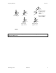
Preparing the Probe Section 3 Fill new membrane cap with 8-9 drops of MEA probe solution. Unscrew guard Unscrew cap Screw cap on tightly by hand Tap cap with finger to remove bubbles. Screw guard on tightly by hand Figure 2 WARNING: Use only YSI MEA probe solution in the membrane cap. Any other solution will damage the MEA sensor.
SECTION 4 OPERATION The following diagram is an overview of the operation of the Model 95. See the following sections for details of operation.
Operation 4.1 Section 4 TURNING THE INSTRUMENT ON With the batteries installed correctly, press the ON/OFF button. The instrument will activate all segments of the display for a few seconds, which will be followed by a self test procedure which will last for several more seconds. During this power on self test sequence, the instrument’s microprocessor is verifying that the system is working properly. If the instrument were to detect a problem, a continuous error message would be displayed.
Operation Section 4 3. The LCD will prompt you to enter the local altitude in hundreds of feet. Use the arrow keys to increase or decrease the altitude. When the proper altitude appears on the LCD, press the ENTER button once. EXAMPLE: Entering the number 12 here indicates 1200 feet. 4. The LCD will prompt you to enter the salinity of the sample(s) that you will be measuring. You can enter any number from 0 to 80 (ppt). Use the arrow keys to increase or decrease the salinity setting.
Operation 4.4 Section 4 STIRRING It is important to realize that even a small amount of stirring will improve the DO and temperature response times in stagnant water, because the transfer process of heat and oxygen will be facilitated by convection. Also, the MEA dissolved oxygen probe is not totally stirring independent due to the consumption of oxygen at the sensor tip during measurement.
Operation Section 4 through the saved sets of data. 4. Depress the DOWN ARROW button to move down through the saved sets of data. 5. When you have finished recalling data, press MODE two times to return to normal operation. NOTE: The Model 95 will recall data as a list. When the UP ARROW is depressed the Model 95 will display the Site ID# for the previously recorded date. For example: If you are reviewing Site ID# 5 and the UP ARROW is depressed the Model 95 will display Site ID#4.
Operation 4.8 Section 4 TOGGLING BETWEEN %-AIR SATURATION AND MG/L The UP ARROW key allows quick and convenient switching between the two DO parameters without going through the instrument’s four modes (using the MODE key). Press the UP ARROW key to toggle the DO reading between %-air saturation and mg/L. 4.9 DISSOLVED OXYGEN FILTER The Model 95 is equipped with a DO filter to help filter out instability and high frequency noise.
SECTION 5 5.1 PRINCIPLES OF OPERATION OPERATION MEA CLARK OXYGEN SENSOR The MEA (microelectrrode array) is a steady-state Clark type polarographic (voltammetric) dissolved oxygen sensor. The sensor is made of a silver anode and a gold cathode (consisting of 100 very small electrodes, each measuring approximately 8 micrometers in diameter) and is separated from the measured medium by a semi-permeable Teflon membrane.
Principals of Operation 5.2 Section 5 DO READINGS FROM THE CATHODE REDUCTION The oxygen reduction current is sampled and processed, by the meter, and displayed as either %-air saturation or mg/L. While the parameter of %-air (partial pressure) is independent of temperature and salinity, mg/L (solubility of oxygen) is a function of temperature and salinity. The same %-air reading (same partial pressure) would give a higher mg/L reading at a lower temperature than at a higher temperature.
SECTION 6 6.1 MAINTENANCE OF THE MEA SENSOR ANODE SERVICE Warning: Under no circumstances should ammonium hydroxide be used to clean the silver anode. Ammonium hydroxide will permanently damage the condition of the MEA surface. The MEA oxygen sensor is, in principle, the same as the conventional Clark oxygen sensor in that the sensor is made of a silver anode and a gold cathode, but the cathode is a microelectrode array.
Maintenance of the MEA Sensor Section 6 Note: The MEA sensor does not require buffing (cleaning) every time the membrane cap is changed. Under normal operating conditions, the MEA sensor should be buffed no more than two times per year. Cathode Cleaning Procedures ü Remove the membrane cap and rinse the sensor thoroughly with deionized or distilled water. ü Place the microcloth on the buffing tool (self-adhesive). Wet the microcloth thoroughly with deionized or distilled water.
SECTION 7 DISCUSSION OF MEASUREMENT ERRORS There are three basic types of dissolved oxygen errors. Type 1 errors are related to limitations of instrument design and tolerances of instrument components. These are primarily the meter linearity and the resistor tolerances. Type 2 errors are due to basic probe accuracy tolerances, mainly background signal, probe linearity, and variations in membrane temperature coefficient.
SECTION 8 TROUBLESHOOTING Symptom 1. Instrument will not turn on 2. Instrument will not calibrate 3. Instrument "locks up" Possible Cause A. Low battery voltage A. Replace batteries (Section 2) B. Batteries installed wrong B. Check battery polarity. (Section 2) C. Meter requires service C. Return system for service (Section 9) A. Membrane is fouled or damaged A. Replace membrane cap (Section 3) B. Probe anode is fouled or dark B. Clean anode (Section 6) C. Probe cathode is fouled C.
Troubleshooting Section 8 10. Main reads “Undr” Probe current too low to calibrate 10. Main display reads “FAIL” A. EEPROM has failed to respond in time. A. Return the system for service (Section 9) A. Meter is in recall mode. A. (Secondary display reads “eep”) 11.
SECTION 9 WARRANTY AND REPAIR YSI Model 95 Dissolved Oxygen Meters are warranted for two years from date of purchase by the end user against defects in materials and workmanship. YSI Model 95 probes and cables are warranted for one year from date of purchase by the end user against defects in material and workmanship. Within the warranty period, YSI will repair or replace, at its sole discretion, free of charge, any product that YSI determines to be covered by this warranty.
Warranty and Repair Section 9 AUTHORIZED U.S. SERVICE CENTERS North and East Region YSI Incorporated • Repair Center • 1725 Brannum Lane • Yellow Springs, Ohio • 45387 • Phone: (800) 765-4974 • (937) 767-7241• E-Mail: info@ysi.
Warranty and Repair Section 9 INTERNATIONAL SERVICE CENTERS YSI Incorporated • Repair Center • 1725 Brannum Lane • Yellow Springs, Ohio • 45387 • Phone: (937) 767-7241• E-Mail: info@ysi.
Warranty and Repair Section 9 CLEANING INSTRUCTIONS NOTE: Before they can be serviced, equipment exposed to biological, radioactive, or toxic materials must be cleaned and disinfected. Biological contamination is presumed for any instrument, probe, or other device that has been used with body fluids or tissues, or with waste water. Radioactive contamination is presumed for any instrument, probe or other device that has been used near any radioactive source.
Warranty and Repair Section 9 Cleaning Certificate Organization ________________________________ Department _________________________________ Address ___________________________________ City _______________ State ______ Zip ________ Country __________________ Model No.
APPENDIX A GENERAL SPECIFICATIONS Materials: ABS, Stainless Steel, and other materials Dimensions: Height: 9.5 inches (24.13 cm) Thickness: 2.2 inches (5.6 cm) Width: 3.5 inches max. (8.89 cm) Weight: 1.7 pounds (w/ 10’ cable) (.77 kg) Display: 2.3”W x 1.5”L (5.8 cm W x 3.
Salinity Compensation Range: 0 to 80 ppt (compensation between 40 and 80 is based on extrapolation) Stirring Dependence: 0.5-mil membrane: <5% error in stagnant water or <2% at a flow rate of 2 in/sec at 120 nA nominal current 1-mil membrane: <3% error in stagnant water or <1% at a flow rate of 2 in/sec at 100 nA nominal current Data Storage: YSI Incorporated 50 points with ID number.
APPENDIX B REQUIRED NOTICE The Federal Communications Commission defines this product as a computing device and requires the following notice: This equipment generates and uses radio frequency energy and if not installed and used properly, may cause interference to radio and television reception. There is no guarantee that interference will not occur in a particular installation.
APPENDIX C ACCESSORIES AND REPLACEMENT PARTS The following parts and accessories are available from YSI or any Franchise Dealer authorized by YSI. YSI Order Number Description 9501 Replacement Membrane Cap Kit, 0.
APPENDIX D UNIT CONVERSION Conversion Chart To Convert From To Equation Feet Meters Multiply by 0.3048 Meters Feet Multiply by 3.
APPENDIX E OXYGEN SOLUBILITY TABLE Solubility of Oxygen in mg/l in Water Exposed to Water-Saturated Air at 760 mm Hg Pressure. Salinity = Measure of quantity of dissolved salts in water. Chlorinity = Measure of chloride content, by mass, of water. S(0/00) = 1.80655 x Chlorinity (0/00) Chlorinity:0 5.0 ppt 10.0 ppt 15.0 ppt 20.0 ppt 25.0 ppt C Salinity:0 9.0 ppt 18.1 ppt 27.1 ppt 36.1 ppt 45.2 ppt 0.0 14.62 13.73 12.89 12.10 11.36 10.66 1.0 14.22 13.36 11.78 11.07 10.39 2.0 13.
Oxygen Solubility Table Temp Appendix E Chlorinity:0 5.0 ppt 10.0 ppt 15.0 ppt 20.0 ppt 25.0 ppt Salinity:0 9.0 ppt 18.1 ppt 27.1 ppt 36.1 ppt 45.2 ppt 24.0 8.42 7.99 7.59 7.21 6.84 6.50 25.0 8.26 7.85 7.46 7.08 6.72 6.39 26.0 8.11 7.71 7.33 6.96 6.62 6.28 27.0 7.97 7.58 7.20 6.85 6.51 6.18 28.0 7.83 7.44 7.08 6.73 6.40 6.09 29.0 7.69 7.32 6.96 6.62 6.30 5.99 30.0 7.56 7.19 6.85 6.51 6.20 5.90 31.0 7.43 7.07 6.73 6.41 6.10 5.81 32.0 7.
APPENDIX F CALIBRATION VALUES TABLE Calibration values for various atmospheric pressures and altitudes. Note: This table is for your information only. It is not required for calibration. Pressure Inches Pressure of Hg mm Hg 30.23 768 29.92 760 29.61 752 29.33 745 29.02 737 28.74 730 28.43 722 28.11 714 27.83 707 27.52 699 27.24 692 26.93 684 26.61 676 26.34 669 26.02 661 25.75 654 25.43 646 25.12 638 24.84 631 24.53 623 24.25 616 23.94 608 23.62 600 23.35 593 23.03 585 22.76 578 22.44 570 22.13 562 21.
1700/1725 Brannum Lane Yellow Springs, Ohio 45387 USA (800) 765-4974 (937) 767-7241 FAX: (937) 767-9320 Website: http://www.ysi.com E-MAIL: environmental@ysi.