
User Manual
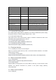

UART0
4
Log output or issue the AT command
COM_UART
2
Flight control data usage
USB
2
HSIC
2
Out to LAN
VCC_HSIC2LAN
1
HSIC to LAN chip 3.3v power supply
I2C3
2
GPIOs
6
Control interactive interrupt information,
etc
VBAT
3
Power
D1V8A
1
1.8V power supply
VRTC
1
RTC battery input 3V
POWER_KEY
1
Boot, high level active, VBAT domain
DLDL
1
Boot download, high level active,1.8-3.3V
DBB_RSTOUT_N
1
Reset button, low effective, 1.8v
D2V85A
1
2.85v interface power supply, for JTAG
3.1.1 Power supply interface
3.1.1.1 Module power supply VBAT
The module power supply shall be supplied by the external stabilized dc power supply
through the VBAT pin, and the voltage range is 3.55v ~ 4.35v.
3.1.1.2 RTC power supply VSB
After VBAT power is off, external power supply is needed to maintain the RTC clock
information, with a typical value of 3V, 1.8-3.3v.
3.1.1.3 D1V8A external power supply
1.8v external power supply, available for external use.
3.1.1.4 D2V85A external power supply
2.85v external power supply, available for external use.
3.1.2 Functional interface
3.1.2.1 POWER_KEY switch on and off signals
Raise 1.5 seconds module start up, lower 1.5 seconds module shutdown, 1.8V~VBAT
voltage domain support;
3.1.2.2 RSTOUT_N reset signal
Output low level 32ms above hardware reset the entire module, 1.8V voltage domain.
3.1.3 Data communication interface
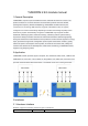
3.1.3.1 USB interface
USB2.0 interface, support HS high-speed transmission.
3.1.3.2 HSIC interface
Support USB2.0 HS high speed, can connect HSIC to LAN chip, connect camera of LAN
interface. For external conversion IC, provide a 3.3v power supply (300mA),
VCC_HSIC2LAN.
3.1.4 Other control interfaces
3.1.4.1 serial port