
Install Instructions

Page 12 of 18
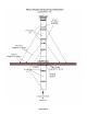
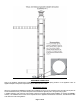
VERTICAL VENTING INSTALLATION
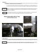
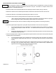
¾ Single wall vent terminations above the roof line must be at least 3 ft. (.9m) high to a maximum of 6 ft. (1.8m) without the
use of lateral supports and 2 ft. (.61 m) higher than any part of a structure within 10 ft. (3.1 m).
¾ Vertical heights greater than 6ft. above the roof shall be supported by Guy Bands. Fasten Guy wires of stainless steel or
galvanized cable with a minimum capacity of 500 lbs. to each of the four anchor holes that are integral to the guy band
and anchor to the roof structure using the appropriate fastening method.
¾ The total vertical distance of the vent system from appliance flue collar to the rain cap termination and the maximum
length of offsets shall not exceed that specified in the appliance manufacturer’s installation instructions.
¾ All horizontal sections must observe the rules for HORIZONTAL VENTING.
1. Prior to beginning the installation, loosely assemble all parts required to make sure all parts are present.
2. Review the venting requirements section in the appliance manufacturer’s installation & operating manual to determine the vent
system configuration.
3. Select and apply the appliance adaptor to the flue outlet collar of the appliance.
4. Locate and mark the breach location(s) of the vertical stack for Fire-stop Support(s) and/or Fire-stop Spacer(s). Refer to
section:
i) INSTALLING FIRE-STOP SUPPORT / SPACER
5. Install the required Fire-stop Support(s) and/or Fire-stop Spacers per the instruction listed above.
6. Continue connecting the required lengths of pipe and fittings starting from the appliance adaptor throughout the system
making certain to follow the instructions in this guide with respect to i) Clearances ii) Joint Procedure, iii) Slope iv) Drain Traps
v) Supports and vi) Vertical Termination.
7. Where a pipe is to install through a Fire-stop Support, insert small end of pipe through loosely connected clamp and insert into
gasket end of mating pipe. Position properly maintaining the correct horizontal slope and tighten the two nut & bolt assemblies
to the plate.
8. Repeat step 6.
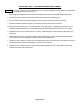
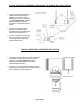
9. Install the Z-Vent Flashing and Top Support / Storm Collar on the pipe and seal around the top edge where the collar meets
the pipe.
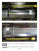
10. Affix the Z-Vent Vertical Termination following the Joint Procedure. (illustration #1 images 1, & 2)