
Install Instructions


Page 7 of 18
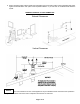
SIDE WALL VENTING INSTALLATION
(see illustration # 2 and images 7 & 8 below)
1. Prior to beginning the installation, loosely assemble all parts required to make sure all parts are present.
2. Review the venting requirements section in the appliance manufacturer’s installation & operating manual to determine the
vent system configuration.
3. Select and apply the appliance adaptor to the flue outlet collar of the appliance.
4. Observing the sidewall vent termination rules on pages 3 & 4 and/or local building codes. Select the point of wall
penetration where the minimum 1/4 “ per foot of slope (6.4 mm per 305 mm) can be maintained.
i) On a non-combustible wall, the pipe may be mortared in directly without using a wall thimble.
ii) A wall thimble is required if terminating is through a combustible wall.
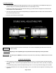
iii) A framed opening is required to insert the thimble halves. The thimble is adjustable for different wall thicknesses.
iv) Install wall thimble into wall. Caulk around outside edge of plates as necessary and fasten to wall using suitable
screws or nails.
v) The termination cap shall be installed no less than 5-1/2 in. from a combustible exterior sidewall (see pg. 3
Sidewall Clearances).
vi) The vent pipe must be sealed at wall thimble as per code regarding continuous vapor barrier.
5. Continue connecting the required lengths of pipe and fittings starting from the appliance adaptor throughout the system
making certain to follow the instructions in this guide with respect to i) Joint Procedure, ii) Slope iii) Supports iv)
Clearances, v) Drain Traps and vi) Side Wall Termination.
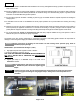
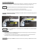
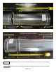
6. Installing the Z-Vent sidewall termination through the wall thimble is achieved from outside through the wall thimble to
the inside. Perform all joint connections per illustration using JOINT PROCEDURE as described on page # 4.
i) Connect the termination to the required length pipe.
ii) Insert the small end of the pipe through the wall thimble from outside. (Note: The “UP” arrow on the label of the
termination for proper orientation)
iii) Install a gear clamp around the pipe on the inside of wall to within ¼ inch of wall plate to trap the pipe in position so
that the system cannot be moved in or out of wall (see images 7 & 8). This applies to both combustible and non-
combustible walls.
Single wall termination shown
Image 7 Image 8
7. The system must be supported along its horizontal length every forty-eight inches or less and at all elbow locations using
suitable supports around pipes (See Illustration #2) maintaining clearance to combustibles as per table 2 on page 6.
8. The horizontal distance of the system from the appliance flue collar to the outside of the horizontal termination shall not be
greater than that specified in the appliance manufacturer’s installation instructions.
Vent Pipe Slope
All horizontally installed portions of a vent system shall have a slope (upwards for Category II, III, or IV
appliances) not less
than 1/4” (6.4 mm) every 12 inches (305 mm) to prevent collection of condensate at
any location in the vent system. This condensate shall be directed to a condensate drain installed
within the system.
NOTICE