0SVSINSCOM Z-VENT® INSTALLATION AND MAINTENANCE INSTRUCTIONS 3"- 24" SINGLE AND DOUBLE WALL SPECIAL STAINLESS STEEL VENTING SYSTEM FOR GAS BURNING APPLIANCES CATEGORY I, II, III, & IV UL1738 & ULC-S636 Read the following before installation of venting system. * Examine all components for possible shipping damage prior to installation. * * The vent system must be free to expand and contract. Check for unrestricted vent movement through walls, ceilings and roof penetrations.
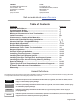
CANADA: FLEXMASTER CANADA LTD. 452 ATTWELL DR. ETOBICOKE, ONTARIO M9W 5C3 (416) 679-0045 U.S.A.: Z-FLEX® US, INC. 20 COMMERCE PARK, NORTH BEDFORD, N.H. 03110-6911 1(800) 654-5600 Visit our web site at www.z-flex.com Table of Contents Contents Hazard Definitions.............................................................. Contaminants Notice....................................................................... Observations to Note....................................................................
Contaminants Notice It is understood that all appliances requiring inside combustion air must have sufficient supply of the air for proper combustion of the fuel air mixture within the appliance. What may not be understood is this supply of air shall be free of corrosive contaminants. Air mixture containing corrosive contaminants when under fire through the combustion process of the appliance produces exhaust gases containing these corrosive contaminants.
WARNING! Running vent exterior to a building may present a freeze concern, especially when venting condensing appliances. To address this concern vent runs shall be; short as possible, horizontal vent pitch should be ¼ in. per 1 ft. up to termination, elbows shall be reduced, exterior tees shall be eliminated, drains shall be located at least 2 ft. inside a heated space, double wall vent shall be utilized for entire vent run (interior & exterior).
NOTICE A. The Z-FLEX® SPECIAL STAINLESS VENT SYSTEM is for use only with appliances having a positive vent pressure of 8" of water column or less. B. Except for installation in one and two family dwellings, a venting system that extends through any zone above that on which the connected appliance is located shall be provided with an enclosure having a fire resistance rating equal to or greater than that of the floor or roof assemblies through which it passes C.
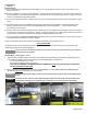
DOUBLE WALL: NOTICE Proper pipe orientation is essential to achieve effective condensate flow. In most cases the use of an appliance specific flue collar adaptor is required to connect directly to the appliance. This adaptor will configure the vent orientation with the gasket end of pipe and fittings towards termination. Also: Some flue collars may require the use of high temperature silicone sealant to make a positive pressure gas tight seal. DOUBLE WALL SNAP-LOCK: 1.
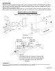
Image 9 Non-Combustible Material is defined as material that is not capable of being ignited or burned, such material consisting entirely of, or a combination of, steel, iron, brick, tile, concrete, slate, glass, plaster (Source: NFPA-54 / ANSI 2223.1-1999) Table 2: Clearance to Combustible Materials NOTICE For double wall clearance is measured from the outer surface (double wall) of vent section.
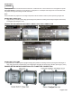
HORIZONTAL / SIDE WALL VENTING INSTALLATION - CATEGORY III & IV APPLIANCES (See Illustrations 1 & 3 and Images 10 & 11 or 12 & 13 for Double Wall ZV-Clamp) 1. Prior to beginning the installation, loosely assemble all parts required to make sure all parts are present. 2. Review the venting requirements section in the appliance manufacturer's installation & operating manual to determine the vent system configuration. 3. Select and apply the appliance adaptor to the flue outlet collar of the appliance. 4.
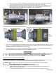
Table 4: Double Wall ZV-Clamp Wall Thimbles WARNING! Review appliance manufacturer's instructions and verify above clearances in Table 3 or 4 for Wall Thimble is appropriate as it may be necessary to increase Combustible Wall Inside Opening MINIMUM for additional clearance. iv. v. vi. Install wall thimble halves into wall; note inside wall plate may have tabs for gear clamp and may have ventilation holes / openings.
ii. Insert the small end of the pipe or adjustable pipe of Double Wall ZV-Clamp wall thimble through the wall thimble from outside. (Note: The "UP" arrow on the label of the termination for proper orientation) iii. Install a gear clamp through tabs and around the pipe on the inside of wall to within ¼ inch of wall plate to secure the pipe in position so that the system cannot be moved in or out of wall (See Images 10 & 11 or 12 & 13 for Double Wall ZV-Clamp).
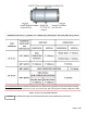
WARNING! Cut pipe joint connections not meeting the full insertion criteria can cause personal injury, death or substantial property damage. Image 14 NOTICE Image 15 Double wall pipe MUST NOT be cut. Adjustable pipe must be considered (Refer to the Double Wall Adjustable section on pages 12 & 13). Single Wall Adjustable: ► It is recommenced to use an adjustable pipe for a non-standard vent length to avoid cutting a vent pipe.
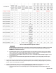
Single Wall Adjustable Part ID Vent Min. Max. Overall Adjustment Diameter Effective Effective Length Length Range "B" Length "A" End Lengths "C" 2SVSALS3 3 11.90 7 9.90 2.90 2 2SVSALS4 4 11.90 7 9.90 2.90 2 2SVSALM3 3 15.90 9 13.90 4.90 2 2SVSALM4 4 15.90 9 13.90 4.90 2 2SVSPA05 5 17.75 2* 15.75 13.75 2 2SVSPA06 6 17.75 2* 15.75 13.75 2 2SVSPA07 7 17.75 2* 15.75 13.75 2 2SVSPA08 8 17.75 2* 15.75 13.75 2 2SVSPA09 9 17.75 2* 15.75 13.75 2 2SVSPA10 10 17.75 2* 15.75 13.75 2 2SVSPA12 12 17.75 2* 15.75 13.
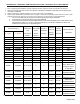
Double Wall Adjustable SNAP-LOCK: Image 18 Image 19 Double Wall Adjustable ZV-CLAMP: Image 20 Double Wall Adjustable SNAP-LOCK Part ID 2SVDALM3 Image 21 Double Double Double Wall Double Wall Vent Double Wall Wall Min. Wall Adjustable Diameter Max. Effective Overall Effective Adjustment ZV-CLAMP "A" Length "C" Length Length Range Part ID "B" 3 16 9 13.9 4.9 End Length "D" 2 2SVDALM4 4 16 9 13.9 4.9 2 2SVDPA05 5 17.75 9* 15.5 6.5 2 2SVDPA06 2SVDPA06V 6 17.75 9* 15.5 6.
Condensate Tube Installation: ► ► The Z-Flex Silicone Tube Kit contains: 3/8 inch ID tube (various lengths), 1 hose (wire) clamp ½ inch, 2 cable ties. When installing the condensate tube be sure to make a trap by forming at least a 3 inch (75 mm) diameter loop and secure with cable tie.
Illustration 3 INSTALLATION OF HORIZONTAL SUPPORTS IMPORTANT: The vent system MUST be supported DURING THE POINT OF INSTALL. Example: 1) From your selected termination point at the wall you can prepare your support locations by temporarily placing one end of a straight length of wood such as a 2" x 2" or 2" x 4" or broom handle in the prepared termination location. 2) Lower the other end of this length of wood to make certain that you have sloped / pitched your horizontal run properly.
1. Prior to beginning the installation, loosely assemble all parts required to make sure all parts are present. 2. Review the venting requirements section in the appliance manufacturer's installation & operating manual to determine the vent system configuration. 3. Select and apply the appliance adaptor to the flue outlet collar of the appliance. 4. Locate and mark the breach location(s) of the vertical stack for Firestop Spacer(s) and/or Firestop Spacer Support(s) and Roof Jack Support.
Image 24 Image 25 ► Measure the dimensions of the selected spacer brackets to determine the hole size that must be cut into the floor or consult Table 7 if part I.D. matches. ► Transfer this dimension to the predetermined breaching floor locations and cut hole. ► Cut a square hole and clear any flooring material so that a proper frame can be installed. i.
Firestop Part ID Firestop Support Part ID Single Wall or Single Wall Combustible Double Wall or Double Fire Stop Ceiling Inside (Inner/Outer) Wall Outer to Outer Plate Opening Diameter Combustible Dimensions MINIMUM (Nominal) Clearance 2ZVFS03 2ZVFSS03 3" 2ZVFS04 2ZVFSS04 4" 2ZVFS05 2ZVFSS05 5" or 3”/5” 2ZVFS064DW 2ZVFSS064DW 4”/6” 2ZVFS075DW 2ZVFSS075DW 5”/7” 2ZVFS06 2ZVFSS06 6" 2ZVFS07 2ZVFSS07 7" 2ZVFS08 2ZVFSS08 8" or 6”/8” 2ZVFS09 2ZVFSS09 9" or 7”/9” 2ZVFS10 2ZVFSS10 10" or 8”/10” 2ZVFS11 2ZVFSS11
INSTALLING ROOF JACK SUPPORT SYSTEM NOTICE The Roof Jack Support System is available from 5" thru 24" and is recommended to be used on all through the roof vent terminations having multiple joints above the roof line with combustible or non-combustible roof structures. ► Prepare the breach location of the roof that will accept the Roof Jack Support System by drilling a small hole, marking the center of the vent termination.
► Cut a square hole and clear any roofing material so frame with proper minimum opening can be installed (See Table 9). ► When cutting the opening, allowance must be made for the thickness of the frame. NOTICE In the event that roof joists must be cut - follow the building codes having jurisdiction for reframing the opening. ► For roof curb installations (recommended): Refer to minimum opening in Table 9 for framing size for masonry pour and Table 8 for roof jack dimensions.
INSTALLING VENT INTO AN EXISTING MASONRY CHIMNEY NOTICE A masonry chimney flue may be used to route vent through provided that no other appliance is vented directly into the same flue without a chimney liner. ► Prior to beginning the installation make certain that the existing chimney meets all national and local building codes. ► The chimney must be cleaned, removing all soot, debris and creosote before installing vent.
Illustration 9 Guy Band Coupler Support Part ID - 2SVSGBS_ _ (See Illustration 10) This guy band coupler can be used in the vertical & horizontal orientation providing additional rigidity & support when in final position (guy wires by others). Not required on double wall with ZV-Clamp unless vent is mounted exterior 6 feet above the roof. Tighten the lock-nuts onto the bolts that clamp the assembly onto the pipe to a torque specification of 70 in/lbs. / 6 ft-lbs. / 8 Nm.
Illustration 11 Floor / Base Support Part ID - 2SVSFBS_ _ (See Illustration 12) Center the Floor / Base Support under the Vertical Tee making the necessary height adjustment to maintain the proper slope of the vent system. CAUTION! Installer is to allow sufficient space below the Floor / Base Support to properly install the Drain tube with prescribed P-Trap configuration.
Z-Vent® Smoothcore® Installation NOTICE The Z-Vent® Smoothcore® liner is a flexible liner intended for use as a chimney liner in masonry chimneys, factory built chimneys connecting to Category I, II, III or IV Z-Vent® systems. Available in diameters 4, 5, 5.5, 6, 7, 8, 9, 10, 12 inch in a single continuous length up to 35 ft. maximum. To achieve liner lengths longer than 35 ft. in the field, additional Smoothcore® flex lengths can be joined by affixing the 2SVFCON_ _ as prescribed in page 25.
AFFIXING THE FEMALE CONNECTOR ONTO THE SMOOTHCORE® FLEX 1. Measure 1 inch from the end of the usable length and mark around the flex every 90° with a permanent marker joining the marks to make a continuous line. This is the minimum insertion depth. (See Illustration 15) 2. Perform a dry fit by inserting the flex into the female adaptor until it bottoms out. Make note of where the marking lines up. 3. Read the instructions on the supplied 10 oz. sealant tube (1 per Female Connector). 4.
Supports Systems: The support system for the liner should be considered by this point in the install. a. A support system such as below the breaching point in the wall for the system to rest on. b. A support system such as suspending guy wires from an anchor plate at the chimney top affixed to guy bands around the flex liner.
6. Place the flashing over the liner and position down onto the chimney top and tighten the gear clamp onto the liner. i. Seal and anchor the flashing onto the chimney top using the appropriate materials. ii. Trim the liner just above the flashing collar. ( See Illustration 24) 7. Position the rain cap over the flashing with the gear clamps aligned. Lower the rain cap over the flashing so the gear clamp screw heads of both fittings interlock.
Z-FLEX® LIMITED WARRANTY Z-FLEX® ("Seller") extends the following LIMITED WARRANTY for Z-VENT® (the "Z-Vent®"): Seller warrants that at the time of purchase, the Z-Vent® will be free of manufacturer's defects in material and/or workmanship. This warranty shall extend to the original purchaser of the Z-Vent® or, if purchased by a contractor, to the end user.