
Installation Sheet

1 of 2
INSTALLATION INSTRUCTIONS
Model 593PHMR;592PHMR;593PHBR;592PHBR
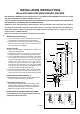
Fig.1
Post
Mounting Screw
Post Fitter
A
B
C
D I
F
G
H
E
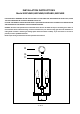
Fig. 2
FOR YOUR SAFETY WARNING: BE SURE THE ELECTRICITY TO THE WIRES YOU ARE WORKING ON IS SHUT OFF; EITHER
THE FUSE IS REMOVED OR THE CIRCUIT BREAKER IS SHUT OFF.
CAUTION: THE PRODUCT SHOULD BE INSTALLED BY A QUALIFIED ELECTRICIAN THAT IS AWARE OF THE CONSTRUCTION
AND OPERATION OF THE PRODUCT AND THE HAZARDS INVOLVED
GENERAL You don’t need special tools to install this fixture. Be sure to follow the steps in the order given. Under no
circumstances should a fixture be hung on house electrical wires, nor should a swag type fixture be installed on a
ceiling which contains a radiant type heating system. Read instructions carefully. If you are unclear as to how to
proceed, consult a qualified electrician.
NOTE: Proper wiring is essential for the safe operation of this fixture.
MOUNTING THE FIXTURE (Fig. 1)
1. Shut off the power at the circuit breaker and remove
the old fixture including the mounting hardware.
2. Carefully unpack your new fixture and lay out all the
parts on a clear area. Take care not to lose any small
parts necessary for installation.
Wiring instruction
3. If you are replacing an existing fixture, remove and
disconnect the old fixture
4. Exposed the wires from the post or the pier mount
supporting the fixture, to make the wire connections
5. Connect the Black wire from the fixture to the black
(hot) supply wire from the post or the pier mount;
connect the White wire from the fixture to the white
(neutral) wire from the post or the pier mount,
Connect the ground wire from the fixture to the
ground wire from the post or the pier mount. Make
sure all wire nuts are secured as per Fig 2. You may
wrap the connections with electrical tape.
6. tuck them carefully inside the post or the pier mount.
7. Place the fixture post fitter (A) onto the post or the
pier mount, and secure with the 3 mounting screws (B)
COMPLETING THE INSTALLATION (Fig. 1)
8.Install the bulb (not provided) into E12 Candle base in
accordance with the fixture’s specification.
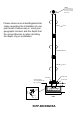
9.Install glass shade (I). (Fig.3)
Align the glass shade (I) to the center rod (E), make
the glass shade (I) sitting in the base (C), put the top
cap (H) and the Gasket (G) on the glass shade, then
tighten top loop (H) on the center rod (E)
DO NOT EXCEED THE MAXIMUM WATTAGE RATING!
Your installation is now complete. Return power to the
junction box and test the fixture
FIXTURE
WIRES
Black or
Smooth
HOUSE
WIRES
Black
(Hot)
FIXTURE
WIRES
White or
Ribbed
HOUSE
WIRES
White
(Neutral)
FIXTURE
WIRES
Bare
Copper
(Ground)
HOUSE
WIRES
Green or
Bare
Copper
(Ground)