FIELD-READY COMMAND C O N S O LE 14 User Manual Z Microsystems Doc# 27-0001UM Issued 7/99 Rev. 1.
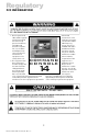
Regulatory FCC INFORMATION 1. Use the power and video cables supplied with the Command Console to help prevent interference with radio and television reception. The use of cables and adapters may cause interference with electronic equipment in the vicinity of this unit. COMMAND C O N S O LE 2. This equipment has been tested and found to comply with the limits for Class A digital devices, pursuant to certain limits imposed by Part 15 of the FCC rules.
Contents STARTING POINT 4 MONITOR ADJUSTMENTS 14 Shipment Contents 4 User Manual 4 REFERENCE 18 System Requirements 4 Product Description 5 TROUBLESHOOTING 20 PREPARATION 6 SPECIFICATIONS 22 INSTALL RAILS 7 APPENDICES 23 INSTALL CONSOLE 8 SUPPORT 24 Further Help 24 FINAL ADJUSTMENTS 9 Replacing Parts 25 Providing Feedback 25 Y2K Compliance 26 CABLES 9 SETUP 11 Closing Console 12 DRAWINGS 27 OPERATION 13 HARDWARE INSTALLATION 29 3 Doc# 27-0001UM Issued 7/99 R
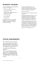
SHIPMENT CONTENTS The Command Console shipping box contains the following: The User Manual comes in two formats: printed hardcopy or CDROM. This Manual is also available on the Z Microsystems website (www.zmicro.com). The Command Console Unit Video Signal Cable AC/DC Power Supply Brick with attached DC cable We recommend you read this manual as follows: AC Power Cable Carefully follow the instructions in the Installation and Testing chapter for hookup and initial control settings.
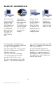
PRODUCT DESCRIPTION The Command Console provides a liquid crystal display, a desk work surface and storage for any size keyboard and mouse in a 3.5" high (2U) standard 19" rack or transit case. Specially designed locks on each side of the Command Console hold the compact folded unit securely in place during storage.
Starting Point TOOLS REQUIRED Required Tools and Equipment Flathead screwdriver with about 10" shaft. Phillips screwdriver with about 10" shaft. Computer Setup Diskette DANGER: To avoid shock hazard: Do not remove the covers around the Command Console. Do not connect or disconnect the Command Console during an electrical storm. The power cord plug must be connected to a properly wired and grounded power outlet.
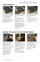
SLIDE REMOVAL With the Console sitting on a workbench with the front facing towards you, press down to release the Z-Locks on each side of the front of the Console to slide the side rails back. Install Rails The slide rail will reach a stop about half way back. The slides should now be separated from the Console. This is a safety stop to prevent the Console sliding out too far while mounted to the rack. Each slide unit includes the slide rail, with the front Z-lock mount and the rear mount.
Install Rails Go back on the rear of the cabinet frame, and fully tighten the three Phillips screws ((W) see page 30 - Install hardware) holding the slide extension rail to the cabinet frame. Make sure you hold the slide mounts hard against the rack rail. 8 Doc# 27-0001UM Issued 7/99 Rev. 1.
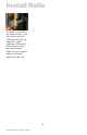
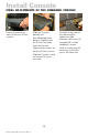
Install Console INSTALL THE COMMAND CONSOLE IN THE SLIDES Pull the two Console slides out until they lock. Hold the Console by each side, with the front toward you. Feed the four cables coming out of the Console back through the cabinet frame. Simultaneously press in the catches on each slide and slide the Console all the way into the cabinet frame. The Console should slide in and out easily. Guide the Console into the slides and slide the Console in until it stops.
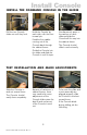
Install Console FINAL ADJUSTMENTS OF THE COMMAND CONSOLE Loosen the screws on each of the front Z-Lock mounts. Slide the Console partially out. Use a flathead screw driver to slightly move the Z-Locks out away from the Console. Tighten all the screws on the front Z-Lock mounts. Slide the Console in and out to see if it moves smoothly. 10 Doc# 27-0001UM Issued 7/99 Rev. 1.2 Go back to the rear of the rack and fully tighten the slide extension rail screw ((U) see page 30 - Install hardware ).screws.
Setup SETTING UP THE MONITOR KEYBOARD AND MOUSE With both hands, press both the Z-Locks down and Slide the Console all the way out. Using both hands, gently lift the Console screen by the top bar. Open the storage tray top. Align the Keyboard and Mouse cable to pass through the recessed access notch. Close the storage tray top, then place the keyboard and mouse on top of the tray door. Remove the keyboard and mouse. The storage tray door now becomes a workstation for the keyboard and mouse.
Closing Console CLOSING DOWN THE MONITOR Remove the keyboard and mouse from top. Open the storage tray top. Slide the Console in with both hands. Place the keyboard and mouse inside the tray along with all cables and close door. Press both the Z-Locks down and slide in the console until you hear the positive click from the lock. 12 Doc# 27-0001UM Issued 7/99 Rev. 1.2 Using both hands, gently drop the Console screen by the top bar until it lays flat.
Operation Switch the Console monitor on by pushing and releasing the power switch marked. Turn on the monitor and then the computer. 13 Doc# 27-0001UM Issued 7/99 Rev. 1.
Monitor Adjustments ON-SCREEN DISPLAY The LCD monitor features an OnScreen Display (OSD) with menus designed to make adjusting the monitor display settings easier. When highlighted, the icons illustrate the control function to assist in identifying which control needs adjustment. preset, the status bar indicates in which direction the adjustments are or button being made. Use the to adjust the control. In addition, a second control icon will appear allowing to toggle between the two controls.
Monitor Adjustments MENU DESCRIPTIONS Select this control to adjust the size and position automatically. It takes a maximum of 10 seconds to complete. AUTO ADJUSTMENT NOTE: This item must operate on full screen image. If it does not, it is possible to operate abnormally. This control allows adjustments to the black level of the display screen. CONTRAST Selection of this control allows making adjustments to the luminosity level of the display screen.
Monitor Adjustments MENU DESCRIPTIONS H-SIZE Select this control, then use the and buttons to expand or decrease the image width to horizontally fill the display screen. LANGUAGE Select this control, then use the and buttons to choose from: English, German (Deutsch), Spanish (Espanol), Italian (Italiano) or French (Francais). COLOR CONTROL Select this control, then use the and buttons to individually adjust R, G or B color.
Monitor Adjustments AUTO CALIBRATION PROGRAM This program cooperates with FPMC firmware which automatically adjusts and saves the panel settings, which will fit each support mode. It takes about 50 seconds for auto adjustment. Follow these steps to start the Auto Calibration Program: NOTE: In order to make it work correctly, first set ON in the OSD menu of the AUTO CALIBRATION item. 1. Insert the Auto Calibration diskette into the 3.5 disk driver. 2.
Reference LED INDICATOR The Power Management feature of the LCD monitor is comprised of three stages: 1. On (green) 2. Standby, Suspend or Active Off (amber/green) 3. Out of Range (amber) TIMING GUIDE The monitor is a multi-frequency monitor. It operates at horizontal frequencies between 31.25KHz and 60.24KHZ, vertical frequencies between 56Hz and 75Hz. Because of its microprocessor-based design, it offers auto-synchronization and autosizing capabilities.
Reference TIMING GUIDE The monitor is not limited to these preset factory-timing modes. In fact, because the monitor is multi-scanning, it can accept any signal within its frequency range of 31.25KHz 60.24KHz horizontal and 56Hz 75Hz vertical. If it is desired to use one of the preset timing modes, refer to the video card manufacturers installation guide for instructions on how to make these changes. The video card controls the refresh rate.
Troubleshooting NO POWER Flip the Power switch ON. The Power LED turns on. Make sure the A/C power cord is securely connected to the power jack and to a power outlet. Plug another electrical device (like a radio) into the power outlet to verify that the power outlet is supplying the proper voltage. Make sure the video cable attached from the monitor is tightly secured to the video output port on the back of the computer. POWER ON BUT NO SCREEN IMAGE Adjust the brightness and contrast.
Troubleshooting DOUBLE (SPLIT) SCREEN IMAGE Make sure the graphics card is set to Non-Interlaced mode. ENTIRE SCREEN IMAGE ROLL (SCROLLS) VERTICALLY Make sure the input signals are within the LCD monitors specified frequency range. (Maximum: VESA 1024x768/75Hz, MAC 1024x768/ 75Hz) Connect the video cable securely. Try the LCD monitor with another power source. CONTROL BUTTONS DO NOT WORK Press only one button at a time. NOTE: The LCD contains over 2,359,926 thin-film transistors (TFTs).
Specifications Power 100 - 240 VAC, 47 - 63Hz, 1.2 A Max Weight 26 lbs. Colors 262,144 Viewing Angle L/R 45/45 Deg. Refresh Rate 1024 x 768 @ 75 Hz Max Display Area 284.9mm (H) x 213.7 mm (V) Up/Down. 15/35 Deg. Operating Temp. 0 to +40 Celsius Storage Temp. -10 to +50 Celsius 22 Doc# 27-0001UM Issued 7/99 Rev. 1.
Appendix PIN ASSIGNMENT 23 Doc# 27-0001UM Issued 7/99 Rev. 1.
Support FURTHER HELP If you are unable to correct the problem yourself, contact: NOTE: For image problems, run AUTO SETUP again before consulting this section. In most cases, AUTO SETUP can fix the problems. See the Auto Setup section for details. Z Microsystems at: (858) 657-1000 Fax: (858) 657-1001 Website: www.zmicro.com Before calling, please have available as much of the following information as possible: 1. Model and serial number from the label on the monitor. 2. Purchase P.O. 3.
Replacing Parts If the Z Microsystems Technical Support Engineer determines that the product needs to be replaced, a Customer Service representative will issue a Return Material Authorization (RMA) number and return address. An RMA number is required to return a product to Z Microsystems, regardless of the reason for the return. The following information is required when returning Z Microsystems products: 1. Model number 2. Serial number 3. Date of purchase 4.
Compliance Y2K COMPLIANCE Z Microsystems has achieved full Y2K Compliance. In late 1997, the companys senior management assigned a Y2K Project Team that consists of a cross-functional representation from information technology, procurement, manufacturing, test and development, finance, general affairs, engineering, marketing and facilities organizations to address the Year 2000 issues.
Drawings 27 Doc# 27-0001UM Issued 7/99 Rev. 1.
Drawings 28 Doc# 27-0001UM Issued 7/99 Rev. 1.
INSTALL HARDWARE · Install the slide assemblies to the rack by installing three screws (V) to the front and three screws (W) to the rear. · Tighten the hex nuts (U) that were installed in the previous page. · Install the command console (FF) into the rack slides. U. V. W. FF. 01-91802 01-92087 01-92097 Nut 8-32 Nylon Hex Scr, 10-32 x .375 Low Hd Scr, 10-32 x .625 Pan Hd Command Console 29 Doc# 27-0001UM Issued 7/99 Rev. 1.
Doc# 27-0001UM Issued 7/99 Rev. 1.
Doc# 27-0001UM Issued 7/99 Rev. 1.
Z Microsystems, Inc. 5945 Pacific Center Blvd., Suite 509 San Diego, CA 92121 Phone: (858) 657-1000 Fax; (858) 657-1001 Website: www.zmicro.com Copyright 1999 Z Microsystems, Inc. All Rights Reserved Doc# 27-0001UM Issued 7/99 Rev. 1.