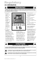
FIELD-READY FIELD-READY COMMAND C O NS O L E 15 User Manual Doc# 27-0002UM Issued 7/99 Rev. 1.
Regulatory FCC INFORMATION 1. Use the power and video cables supplied with the Command Console to help prevent interference with radio and television reception. The use of cables and adapters may cause interference with electronic equipment in the vicinity of this unit. and on, the user is encouraged to try to correct the interference by one or more of the following measures: Reorient or relocate the receiving antenna. Increase the separation between the equipment and receiver.
Contents STARTING POINT Shipment Contents User Manual System Requirements Product Description 4 4 4 4 5 PREPARATION 6 INSTALL RAILS 7 INSTALL CONSOLE 9 FINAL ADJUSTMENTS 10 SETUP 11 CLOSING CONSOLE 12 OPERATION 13 CONFIGURE MONITOR Setup For Windows 95 or 98 Auto Setup Auto Setup for DOS Auto Setup for Windows 3.
SHIPMENT CONTENTS USER MANUAL The Command Console shipping box contains the following: The User Manual comes in two formats: printed hardcopy or CDROM. This Manual is also available on the Z Microsystems website (www.zmicro.com). The Command Console Unit Video Signal Cable AC/DC Power Supply Brick with attached DC cable We recommend you read this manual as follows: AC Power Cable Carefully follow the instructions in the Installation and Testing chapter for hookup and initial control settings.
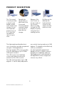
PRODUCT DESCRIPTION The Command Console provides a liquid crystal display, a desk work surface and storage for any size keyboard and mouse in a 3.5" high (2U) standard 19" rack or transit case. Specially designed locks on each side of the Command Console hold the compact folded unit securely in place during storage.
Starting Point TOOLS REQUIRED Required Tools and Equipment Flathead screwdriver with about 10" shaft. Phillips screwdriver with about 10" shaft. Computer Setup Diskette DANGER: To avoid shock hazard: Do not remove the covers around the Command Console. Do not connect or disconnect the Command Console during an electrical storm. The power cord plug must be connected to a properly wired and grounded power outlet.
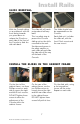
Install Rails SLIDE REMOVAL With the Console sitting on a workbench with the front facing towards you, press down to release the Z-Locks on each side of the front of the Console to slide the side rails back. The slide rail will reach a stop about half way back. The slides should now be separated from the Console. This is a safety stop to prevent the Console sliding out too far while mounted to the rack. Each slide unit includes the slide rail, with the front Z-lock mount and the rear mount.
Install Rails Go back on the rear of the cabinet frame, and tighten the slide mount to the cabinet frame. Make sure you hold the slide mounts hard against the rack rail. 8 Doc# 27-0002UM Issued 7/99 Rev. 1.
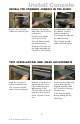
Install Console INSTALL THE COMMAND CONSOLE IN THE SLIDES Pull the two Console slides out until they lock. Hold the Console by each side, with the front toward you. Feed the four cables coming out of the Console back through the cabinet frame. Simultaneously press in the catches on each slide and slide the Console all the way into the cabinet frame. The Console should slide in and out easily. Guide the Console into the slides and slide the Console in until it stops.
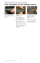
Install Console FINAL ADJUSTMENTS OF THE COMMAND CONSOLE Loosen the screws on each of the front Z-Lock mounts. Slide the Console partially out. Use a flathead screw driver to slightly move the Z-Locks out away from the Console. Tighten all the screws on the front Z-Lock mounts. Slide the Console in and out to see if it moves smoothly. 10 Doc# 27-0002UM Issued 7/99 Rev. 1.2 Go back to the rear of the rack and fully tighten the side rail screws.
Install Console SETTING UP MONITOR KEYBOARD AND MOUSE With both hands, press both the Z-Locks down and Slide the Console all the way out. Using both hands, gently lift the Console screen by the top bar. Open the storage tray top. Align the Keyboard and Mouse cable to pass through the recessed access notch. Close the storage tray top, then place the keyboard and mouse on top of the tray door. Remove the keyboard and mouse. The storage tray door now becomes a workstation for the keyboard and mouse.
Closing Console CLOSING DOWN THE MONITOR Remove the keyboard and mouse from top. Open the storage tray top. Slide the Console in with both hands. Place the keyboard and mouse inside the tray along with all cables and close door. Press both the Z-Locks down and and slide in the console untill you hear the positive click from the lock. 12 Doc# 27-0002UM Issued 7/99 Rev. 1.2 Using both hands, gently drop the Console screen by the top bar until it lays flat.
Operation INSTALLING CABLES 4 cables connect the back of the Console to the computer. Power cable Video cable Keyboard cable Mouse cable To connect the four cables: WARNING: Be sure all electrical power to the cabinet is off before connecting any of the cables. Turn off the computer and all attached devices. WARNING: There is a key guide for alignment on all the cables. Be sure the cable plug and receptacles are aligned properly using the key guide. Misalignment can cause short circuiting.
Configure Monitor The Command Console offers several methods to set up the monitor, depending on the operating system used for your computer. Use the Setup Diskette and select the setup that is best for your computer operating system. When first used, you must perform Automatic Setup (AUTO SETUP). This procedures sets up the monitor to process the video signals from the computer without image discoloration or smearing.
Configure Monitor AUTO SETUP NOTE: After making changes in the Setup, the computer must be Rebooted to insure proper changes to the CONFIG.SYS and AUTOEXEC.BAT files. Locate the operating system installed on the computer in the Table below and follow the appropriate instructions. You may choose to run Auto Setup for each operating system that is used.
Configure Monitor AUTO SETUP FOR WINDOWS 3.1, 95, 98 OR NT 1. Turn the monitor on first, then the computer. If the message CHECK SIGNAL CABLE is displayed. If nothing is displayed check: NOTE: If the monitor is in standby mode (STANDBY ON), it may automatically turn off while you are waiting for it to warm up. that the video interface cable is connected properly. the correct video adapter card is installed. the correct support display mode is selected for the computer.
Configure Monitor 7. Use an Arrow button ( ) to select the Image Lock icon (symbol of Image Lock) and press OSD to access the Enter button function. 8. Using an Arrow button ( ), select Automatic and press the . This actiOSD Enter button vates the Auto Setup procedure, which will optimize the display settings with the provided test pattern. The screen will dim, blink on and off several times, and you may notice small changes to the test pattern. To abort the Auto Setup function, press the Esc key. 9.
Monitor Adjustments User Control Features Making adjustments to the Command Console screen is a matter of performing the following easy On-Screen Display steps: Operation Press any of the OSD control buttons to display the main OSD menu. NOTE: The image is already optimized for many display modes, however the user controls can be used to adjust the image to your liking. Use the Arrow buttons to move among the icons. Select an icon and press OSD Enter to access that function.
Monitor Adjustments OSD Lock/Unlock This feature allows you to secure the current control settings, while allowing the user to adjust Brightness and Contrast, so that they cannot be inadvertently changed, you can unlock the OSD controls at any time by using the same procedure. Push and hold the button 10 seconds to Lock or to Unlock. When locked, a LOCKED message will be displayed.
Monitor Adjustments Initial Appearance of OSD OSD Functions 20 Doc# 27-0002UM Issued 7/99 Rev. 1.
Monitor Adjustments OSD Functions 21 Doc# 27-0002UM Issued 7/99 Rev. 1.
Monitor Adjustments OSD Functions 22 Doc# 27-0002UM Issued 7/99 Rev. 1.
CLEAN MONITOR Maintenance WARNING: To avoid risk of electric shock, do not disassemble the monitor cabinet. Users cannot service the monitor. User maintenance is restricted to cleaning as explained below. • Gently wipe the covers and the screen with a soft cloth. • Remove finger marks and grease with a damp cloth and mild detergent. DO NOT use solvents or abrasives. • Never use flammable cleaning material to clean the monitor or other electrical apparatus.
Troubleshooting WARNING: Be sure to turn off the power before you perform any maintenance on the monitor. CAUSES AND CORRECTIVE ACTION NOTE: For image problems, you may want to run AUTO SETUP again before consulting to this section. In most cases, AUTO SETUP can fix the problems. 24 Doc# 27-0002UM Issued 7/99 Rev. 1.
Troubleshooting 25 Doc# 27-0002UM Issued 7/99 Rev. 1.
Display Modes The display mode the monitor uses is controlled by the computer. Refer to the computer documentation for details on how to change display modes. The image size, position and shape may change when the display mode changes. This is normal and the image can be readjusted using AUTO SETUP and the monitor controls. Unlike CRT monitors, which require a high refresh rate to minimize flicker, TFT technology is inherently flickerfree.
Display Modes POWER MANAGEMENT To benefit from power management, the monitor must be used in conjunction with a computer that implements the Video Electronics Standards Association (VESA) Display Power Management Signaling (DPMS) Standard.
Specifications Display Specifications Display Type Display Area Diagonal Viewing Area Viewing Angle Resolution Color Pixel Size Colors Contrast Ratio Luminance Screen Refresh Input Signal Sync Types AMLCD 15.0 (381 mm) 11.97 (304 mm) x 8.97 (228 mm) 160 degrees (horizontal/vertical) 1024 x 768, RGB Vertical Strip Hor. - 0.297 mm, Ver. - 0.
Specifications Shock 15 G, 11 mS Operating 30 G, 11mS Nonoperating Bench handing per MIL-STD-810E Vibration, Random 3.0G RMS, 20-2,000 Hz Operating 4.0G HMS, 20-2,000Hz Nonoperating Enclosure Weight Sand and Dust Rain NEMA 4/12 at front panel 24 lb. 5.5 M.P.H. for 25 minutes Per MIL-STD-810E, method 506.
Support FURTHER HELP If you are unable to correct the problem yourself, contact: Z Microsystems at: (858) 657-1000 Fax: (858) 657-1001 Website: www.zmicro.com NOTE: For image problems, run AUTO SETUP again before consulting this section. In most cases, AUTO SETUP can fix the problems. See the Auto Setup section for details. Before calling, please have available as much of the following information as possible: 1. Model and serial number from the label on the monitor. 2. Purchase P.O. 3.
Support If the Z Microsystems Technical Support Engineer determines that the product needs to be replaced, a Customer Service representative will issue a Return Material Authorization (RMA) number and return address. An RMA number is required to return a product to Z Microsystems, regardless of the reason for the return. The following information is required when returning Z Microsystems products: 1. Model number 2. Serial number 3. Date of purchase 4. Proof of purchase (use the invoice or packing slip) 5.
Compliance Y2K COMPLIANCE Z Microsystems has achieved full Y2K Compliance. In late 1997, the companys senior management assigned a Y2K Project Team that consists of a cross-functional representation from information technology, procurement, manufacturing, test and development, finance, general affairs, engineering, marketing and facilities organizations to address the Year 2000 issues.
Drawings 33 Doc# 27-0002UM Issued 7/99 Rev. 1.
Drawings 34 Doc# 27-0002UM Issued 7/99 Rev. 1.
Z Microsystems, Inc. 5945 Pacific Center Blvd., Suite 509 San Diego, CA 92121 Phone: (858) 657-1000 Fax; (858) 657-1001 Website: www.zmicro.com Copyright 1999 Z Microsystems, Inc. All Rights Reserved Doc# 27-0002UM Issued 7/99 Rev. 1.