Command Console 19
REGISTRATION WARNING TO PREVENT FIRE OR SHOCK HAZARDS, DO NOT EXPOSE THIS UNIT TO RAIN OR MOISTURE. ALSO, DO NOT USE THIS UNIT’S POLARIZED AS PLUG WITH AN EXTENSION CORD RECEPTACLE OR OTHER OUTLETS UNLESS ALL THREE PRONGS CAN BE FULLY INSERTED 2. Changes or modifications not expressly approved by Z Microsystems could void user’s warranty. 1. Use the power and video cables supplied with the product to help prevent interference with radio and television reception.
TABLE OF CONTENTS SECTION PAGE Introduction ........................................................................................................................4 About This Manual ....................................................................................................4 Safety Precautions....................................................................................................4 Product Description ...................................................................................
INTRODUCTION ABOUT MANUAL This Manual is also available on the Z Microsystems website (www.zmicro.com). We recommend you read this manual carefully and follow the instructions in the Installation chapter for verification of system functions and control settings. SAFETY PRECAUTIONS DANGER: To avoid shock hazard: • Do not remove the covers around the Command Console • Do not connect or disconnect the Command Console during an electrical storm.
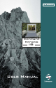
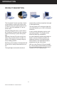
INTRODUCTION PRODUCT DESCRIPTION The Command Console provides a liquid crystal display, a desk work surface and storage for any size keyboard and mouse in a 3.5” high (2U) standard 19” rack or transit case. construction provides exceptional strength in field applications. The high quality LCD screen provides full color and features up to 1280 x 1024 pixel resolution. Specially designed locks on each side of the Command Console hold the compact folded unit securely in place during storage.
INSTALLATION SHIPMENT CONTENTS DANGER: To avoid shock hazard: Ensure all of the following parts are included in the package received from Z Microsystems. Verify all parts have not been damaged during shipment. If any of the parts are missing or damaged, immediately contact Z Microsystems Customer Service at 858-657-1000. • Do not remove the covers around the Command Console. • Do not connect or disconnect the Command Console during an electrical storm.
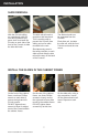
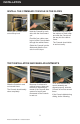
INSTALLATION SLIDE REMOVAL With the Console sitting on a workbench with the front facing towards you, press down to release the Z-Locks on each side of the front of the Console to slide the side rails back. The slide rail will reach a stop about half way back. This is a safety stop to prevent the Console from sliding out too far while mounted to the rack. Simultaneously press in the safety catches on each slide rail and slide the side rails all the way off the back of the Console.
INSTALLATION APPENDIX Go back on the rear of the cabinet frame, and fully tighten the three Phillips screws holding the slide extension rail to the cabinet frame. Make sure you hold the slide mounts hard against the rack rail. 8 Doc# 27-0023UM Rev 1.
INSTALLATION APPENDIX INSTALL THE COMMAND CONSOLE IN THE SLIDES Pull the two Console slides out until they lock. Hold the Console by each side, with the front toward you. Feed the four cables coming out of the Console back through the cabinet frame. Guide the Console into the slides and slide the Console in until it stops. Simultaneously press in the catches on each slide and slide the Console all the way into the cabinet frame. The Console should slide in and out easily.
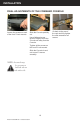
INSTALLATION FINAL ADJUSTMENTS OF THE COMMAND CONSOLE Loosen the screws on each of the front Z-Lock mounts. Slide the Console partially out. Use a flathead screw driver to slightly move the Z-Locks out away from the Console. Tighten all the screws on the front Z-Lock mounts. Slide the Console in and out to see if it moves smoothly. NOTE: A wrench may be necessary to hold the nut on the other side. 10 Doc# 27-0023UM Rev 1.
INSTALLATION SETTING UP THE MONITOR KEYBOARD AND MOUSE With both hands, press both the Z-Locks down and Open the storage tray top. Remove the keyboard and mouse. Slide the Console all the way out. Align the Keyboard and Mouse cable to pass through the recessed access notch. The storage tray door now becomes a workstation for the keyboard and mouse. There should be ample cable to both units for movement around the workstation. 11 Doc# 27-0023UM Rev 1.
INSTALLATION APPENDIX CLOSING DOWN THE MONITOR Remove the keyboard and mouse from top. Open the storage tray top. Slide the Console in with both hands. Place the keyboard and mouse inside the tray along with all cables and close door. Press both the Z-Locks down and slide in the console until you hear the positive click from the lock. 12 Doc# 27-0023UM Rev 1.0 Issued 09/04 Using both hands, gently drop the Console screen by the top bar until it lays flat.
INSTALLATION CABLE CONNECTIONS Check that all cables are plugged in properly. PIP INPUT (OPTIONAL) PIP INPUT (OPTIONAL) AC POWER INPUT HOST SERIAL INPUT VIDEO INPUT REAR VIEW J5 J4 J1 Primary Video Input J2 Host Input J3 PIP Card #1 I/O Connector J4 PIP Card #2 I/O Connector J5 AC Power Line POWERING UP Turn on the monitor and then the computer. 13 Doc# 27-0023UM Rev 1.
OPERATIONS DISPLAY PANEL CONTROLS The Command Console features push-button controls on the lower front of the front bezel. To setup the display, use the following controls to fine tune the image on the screen: NOTE: The following procedures are written for setup using the buttons on the display panel. See the “SoftMenus” section of this manual for remote setup.
OPERATIONS DISPLAY PANEL SETUP NOTE: If the touch screen option has been purchased for the Command Console, the touch screen manufacturer’s software must first be installed on the computer being used with the Command Console. Follow manufacturer’s instructions and user manual for software installation and use. This following section explains how to use the control buttons to adjust, image clarity and image position on the screen.
OPERATIONS ONSCREEN MENUS NOTE: When the unit is initially connected, no pip screens are enabled, and therefore can not appear. See section titled “pip configuration” for how to enable pip screens. To access the onscreen display main menu, press the menu button on the front of the panel. All 2UCCs functions are controlled using the Main Menu’s subtopics. These submenus can be accessed using the Up and Down buttons on the display panel. See sections below for specifics regarding the submenus.
OPERATIONS Main Screen Graphics Mode Use the Up and Down buttons to highlight the “Graphics Mode” option. Press the “Menu” button to access the “Graphics Mode” submenu. “Graphics Mode” is used to adjust the positioning of the image. Use the Left and Right buttons to adjust the following modes: Horz Coarse, Horz Fine, H Pos, and V Pos. The “Horz Coarse” option adjusts the horizontal width of the image. The “Horz Fine” option adjusts the phase of the video sampling clock.
OPERATIONS Main Screen Information Use the Up and Down buttons to highlight the “Information” option. Press the “Menu” button to access the “Information” submenu. Within this submenu, view the video mode resolution, the refresh rate, and the sync mode. Press “Exit” to return to the Main Menu. Menu Timeout: Main Screen Configuration #/.&)'52!4)/. -ENU 4IMEOUT The menu timeout is the amount of time the menu will appear while not in use before it times out.
OPERATIONS KVM Control (see KVM on screen on previous page): Toggles ON/OFF to apply or remove preset KVM command features. The preset commands are programmed as alternate functions of the firmware buttons on the front of the panel. For predefining the KVM character strains, please refer to SoftMenu instructions regarding KVM Control. RGB/Video PIP Control Screens NOTE: When the KVM Control is turned ON, the Main Menu requires the button be held down for extended length of time to be made active.
OPERATIONS APPENDIX FROM THE RGB PIP MENU Once the desired RGB PIP is highlighted, press the “Menu” button on the display to access the RGB PIP submenu. Within the submenu, the following options are accessible: RGB PIP Geometry Use the Up and Down buttons to highlight the “Geometry” option. Press the “Menu” button to access the “Geometry” submenu.
OPERATIONS APPENDIX RGB PIP Image Quality Use the Up and Down buttons to highlight the “Image Quality” option. Press the “Menu” button to access the “Image Quality” submenu. Within this submenu, highlight the item to adjust, and use the Left and Right buttons to alter the PIP Contrast, the Horz Coarse and the Horz Fine characteristics. Press “Exit” to return to the RGB PIP submenu. The new adjustments will be applied automatically.
OPERATIONS FROM THE VIDEO PIP MENU Once the desired Video PIP is highlighted, press the “Menu” button on the display to access the Video PIP submenu. Within the submenu, the following options are accessible: Video PIP Geometry Use the Up and Down buttons to highlight the “Geometry” option. Press the “Menu” button to access the “Geometry” submenu.
OPERATIONS Video PIP Configuration PIP ENABLE: From the Main Menu, use the Up and Down buttons to locate the desired Video PIP. Once highlighted, press the Menu button again to access the PIP submenu. Use the Up and Down buttons to highlight the “Configuration” option. Press the Menu button to enable the “PIP Configuration” submenu. Highlight the “PIP Enable” option and press the Left or Right buttons to choose the “ON” option. The PIP screen will appear.
OPERATIONS SOFTMENUS™ SoftMenus™ are control panel dialog screens accessed from the host computer, allowing flexibility where positioning and environmental demands are a concern. In order to access the SoftMenu™ features, the host serial port must be accessed at the rear of the Command Console. The Command Console must be connected to the computer and software must be installed.
OPERATIONS Monitor SoftMenus™ The Monitor SoftMenu™ dialog screen allows the operator to adjust Channel Configuration activity, Default settings, Auto Adjust, Brightness and Contrast characteristics, Coarse and Positioning range, and Color Balancing of the main screen image in one easy-to-use menu. Monitor Screen “Factory Default” and “Auto Adjust” Buttons To adjust the monitor screen settings, the “Monitor” tab must be active.
OPERATIONS PIP SoftMenus™ The PIP SoftMenu™ tabs allow the operator to choose RGB and NTSC PIP Color Balancing and Image Quality or Video Settings configurations, as well as Factory Default settings and Chroma keying. The settings for the RGB and NTSC PIPs will be different. PIP “Factory Default” Button Before any changes can be made, choose the desired PIP tab (PIP1 or PIP2). Once the correct PIP tab screen is activated, settings can be altered.
OPERATIONS “Enable” and “Hide/ Show Wrapper” Click the “Enable” box to enable the chroma keying function. The “Hide/Show Wrapper” toggle key, when enabled, allows the operator to wrap the GUI PIP wrapper around the PIP image or hide it. “Color Palette” and “Enter Color” The PIP chroma keying Color Palettes and manual color values can be accessed with the “Color Palette” and “Enter Color” buttons. See below for details regarding manual and default color operation.
OPERATIONS To choose from a larger palette, left click on the “Number of Colors” drop-down menu and move the cursor down to the desired number of colors in the palette. The corresponding palette will appear. Simply choose a color by clicking on it. 28 Doc# 27-0023UM Rev 1.
OPERATIONS Video Resync Option If the Video Resync option has been chosen for the unit, please note the following capability. If the NTSC PIP image fails and does not recover, the “Video Resync” button will enable the PIP board to reanalyze the video input stream in an attempt to recover the image. 29 Doc# 27-0023UM Rev 1.
OPERATIONS Menu Bar The SoftMenus’ menu bar also includes the “Edit” and “Tools” drop-down menus. Left click on any of the following drop-down menus: File Load previously saved display settings and save settings in the “File” drop-down menu. Multiple users may wish to alter the settings individually with this feature. Edit Manage, add, and remove the ports used by SoftMenus for communication with the “Edit” drop-down menu. 30 Doc# 27-0023UM Rev 1.
OPERATIONS Tools Manage the Chroma key and Zoom status of the various PIPs; allows the user to maintain activity in one tab window while simultaneously altering the chroma key and zoom functionality of a different PIP. Zoom The Zoom feature allows the user to focus on a certain area of the screen. There are two ways to enable Zoom: 1. Tools drop-down menu>PIP#>Zoom>Enable, as shown here: 2. Independent PIP Configuration Panels on the PIP tabs.
OPERATIONS NOTE : While Zoom is enabled in SoftMenus, the Chromakey function must remain enabled. HOT KEYS Hot Keys are only available on the Linux and Windows versions of Z Microsystems’ software. The following combinations of “hot” keys have been customized for ease of use of the Command Console. Ctrl + Tab Press the “Control” and the “Tab” keys simultaneously to toggle between the Main Monitor and PIP tabs, from left to right. Ctrl + PIP # 1, 2, 3, etc.
OPERATIONS KVM Control (optional) The SoftMenus KVM Control feature enables the display to communicate with the KVM over the serial port. The ASCII string assignments can only be configured through SoftMenus. To assign or alter the ASCII strings, click on the SoftMenus’ Tools drop-down menu. Left click on the “KVM Setup” option and the following screen will appear: The button images map to the physical buttons on the display panel.
MAINTENANCE MAINTAINING THE COMMAND CONSOLE WARNING: Be sure to turn off the power before you perform any maintenance on the monitor. WARNING: To avoid risk of electric shock, do not disassemble the monitor cabinet. Users cannot service the monitor. User maintenance is restricted to cleaning as explained below. CLEANING THE MONITOR Unplug the monitor from the power outlet before cleaning. • To clean the flat panel display screen, lightly dampen a soft, clean cloth with water or mild detergent.
TROUBLESHOOTING TROUBLESHOOTING THE COMMAND CONSOLE No Main Display Image If there is no image on the main screen, a signal will appear on the screen that states, “No Input, Check Cable”. If the cable from the computer to the display is secure, determine the color of the standby LED and follow the appropriate procedure below. Black Problem: If the standby LED is black, there is no power to the unit. NOTE: These procedures only apply to the main screen image, not the picture-in-picture screens.
TROUBLESHOOTING No Picture-in-Picture Option Appears on Main Menu If no PIP menu is available from the Main Menu (where PIP is installed), the PIP has not been detected by the controller. Recycle power to the unit by disconnecting power and then reconnecting power. If no PIP is detected again when the Main Menu is powered up again, call Z Microsystems’ Customer Support Department for assistance.
TROUBLESHOOTING Display Image Has Vertical Bars If the main image begins to display vertical bars, adjust the “Horz Coarse”. From the Main Menu, use the Up and Down buttons to highlight the “Graphics Mode” option. Press the “Menu” button to access the “Graphics Mode” submenu. Use the Left and Right buttons to adjust the screen until the number of bars is reduced. Continue adjusting one step at a time until the bars are no longer visible.
REPLACEMENTS REPLACING PARTS If the Z Microsystems Technical Support Engineer determines that the product needs to be replaced, a Customer Service Representative will issue a Return Material Authorization (RMA) number. An RMA number is required to return a product to Z Microsystems, regardless of the reason for the return.
SPECIFICATIONS SPECIFICATIONS FOR COMMAND CONSOLE The Command Console is designed to host a choice of LCDs from several manufacturers based upon customer requirements. The specifications unique to each particular LCD vary from manufacturer to manufacturer. These particular specifications are available through our sales department. General Display Specifications Display size 19 Inch Resolution Up to 1280 x 1024 Color Palette 16.7 Million Contrast Ratio 700:1 (typ) Pixel Pitch .294 mm x .
SPECIFICATIONS Shock MIL-STD-810E (Method 516) 30 g’s MIL-S-901D (in isolated rack) Fungus Non-Nutrients/Contaminants Sand and Dust 5.5 MPH for 25 mins (display bezel only) Drip MIL-STD-810E (display bezel only) Reliability MTBF Display: 20,000 hrs w/ backlight change at 10,000 hrs.
SCHEMATICS MECHANICAL OUTLINE FOR COMMAND CONSOLE ISOMETRIC VIEW CLOSED ISOMETRIC VIEW OPEN ISOMETRIC VIEW OPEN WITH KEYBOARD COVER OPEN 41 Doc# 27-0023UM Rev 1.
Doc# 27-0023UM Rev 1.0 Issued 09/04 .17 .11R FRONT VIEW REAR VIEW 18.20 19.06 3.50 .25 .63 1.25 HOST SERIAL INPUT VIDEO INPUT PIP INPUT (OPTIONAL) KEYBOARD/MOUSE CABLE ACCESS AC POWER INPUT PIP INPUT (OPTIONAL) 1.72 24.00 TO 30.00 LONG RACK 23.69 16.
1.97 43 Doc# 27-0023UM Rev 1.0 Issued 09/04 .17 .10R 15.54 8.19 SECTION A-A 18.12 1.80 KEYBOARD AREA 23.73 A A .25 .63 1.25 18.
APPENDIX WARRANTIES Standard Warranty -no charge- Z Microsystems’ one-year Standard Warranty includes a 90-day AirSpare Service Plan. This means that if any standard Z Microsystems’ product fails within the first 90 days after shipping, the customer will receive a new replacement. All non-standard* products are covered for one year under Z Microsystems’ Standard Warranty that includes free parts and labor. However, the 90-day AirSpare Plan can be purchased as an additional option for non-standard products.
APPENDIX Z Extended Warranty Z Microsystems’ Extended Warranty Plan provides one and two year extended warranty options under which a Standard Warranty is extended from the end of the first year of the Standard Warranty period. The One-Year Extended Warranty period will begin on the day the Standard Warranty expires and the Two-Year Extended Warranty begins when the One-Year Extended Warranty expires.
APPENDIX Z Preferred Warranty Z Microsystems provides a Preferred Service Plan under which Z Microsystems will repair or replace and return a defective product to the customer within one week of Z Microsystems’ receipt of the defective product.
APPENDIX Z Airspare Warranty 365 DAYS Z Microsystems provides an AirSpare Service Plan that will replace a defective product, within the first year of the warranty period, with a new product the following business day.* The AirSpare Service Plan does not cover special order items. A product may be deemed a special order item at the discretion of the Customer Service Department.
APPENDIX Z On-Site Service Z Microsystems also provides on site service and consultation to customers who require Z Microsystems’ technical expertise. 48 Doc# 27-0023UM Rev 1.
APPENDIX Disclaimer Z Microsystems warrants that every product is free from defects in materials, workmanship and conforms to Z Microsystems’ stringent specifications. Z Microsystems calculates the expiration of the warranty period from the date the product is shipped. This means that the ship date on your invoice begins your warranty, unless Z Microsystems informs you otherwise. During the warranty period, Z Microsystems will provide warranty service under the type of warranty purchased for the product.
APPENDIX CUSTOMER SUPPORT NOTE: For image problems, run AUTO SETUP again before consulting this section. In most cases, AUTO SETUP can fix the problems. See the Auto Setup section for details. NOTE: If possible, stay by the computer. The Z Microsystems Technical Support Representative may wish to go through the problem over the telephone. If you are unable to correct the problem yourself, contact: Z Microsystems at: (858) 657-1000 Fax: (858) 657-1001 Website: www.zmicro.
APPENDIX CUSTOMER FEEDBACK We value feedback on our products, their performance, problems found, and welcome all constructive suggestions. Please send such productive information in writing to: Customer Service Z Microsystems 5945 Pacific Center Blvd., Suite 505 San Diego, CA 92121 or www.zmicro.com 51 Doc# 27-0023UM Rev 1.
APPENDIX COMMAND CONSOLE SERIAL CONTROL ICD The following serial port property settings must be in place in order for the host to have communication with the display. SPEED 19,200 BPS DATA BITS 8 PARITY None STOP BITS 1 The serial control ICD commands are presented here for the user’s knowledge. The commands are written and controlled by Z Microsystems and are not intended for the customer to use.
APPENDIX properly position itself if an uncommon image stream is provided to the display. Argument No arguments. PBB Description PBB adjusts the blue balance of the main images RGB setting. Argument The allowable range is 0-255 base10. The factory default is 128. PBG Description PBG adjusts the green balance of the main images RGB setting. Argument The allowable range is 0-255 base10. The factory default is 128. PBR Description PBR adjusts the red balance of the main images RGB setting.
APPENDIX PDS Description PDS has the display place all of the settings back to the factory defaults. Argument No arguments. PHC Description PHC adjusts the horizontal coarse setting. Argument The allowable range is 0-255 base10. The factory default is 128. PHF Description PHF adjusts the horizontal fine setting. Argument The allowable range is 0-248 base10. The factory default is 119. PHP Description PHP adjusts the horizontal position of the image. Argument The allowable range is 76-180 base10.
APPENDIX PVP Description PVP adjusts the vertical position of the image. Argument The allowable range is 106-150 base10. The factory default is 128. Non-Standard Command Structure The following commands do NOT use the standard command structure. They are sent “as is” to the controller, succeeded by a carriage return (CR). EPROM SAVE Description EPROM SAVE instructs the controller to store the display settings.
APPENDIX No arguments. Return The number of the first RGB PIP card. There are two valid values that this command can return “0” or “1”. If there is an RGB PIP provided with the display this command is issued to then “1” will be returned otherwise “0” is returned indicating that there is not an RGB PIP present. The syntax for the returned value is the following: =~~~~ where “value” = the number of the first RGB PIP.
APPENDIX provide for PIP# in the command structure namely “0”, “1”, “2”, and “3”, where “0” acts on the main image and “1”, “2”, and “3” act on the RGB PIP specified. RGB PIP The following commands are those that act on the RGB PIPs contained in the display’s configuration. PBB Description PBB adjusts the blue balance of the picture-in-picture’s RGB setting. Argument The allowable range is 0-255 base10. The factory default is 128.
APPENDIX Argument No arguments. PHB Description PHB sets the upper-bound of the blue portion of the RGB value used for chroma key. The upper-bound of the color is determined by taking the color value that is desired (0-255) and adding a guardband value to take into account accuracy limitations of the hardware. The upper-bound limit is still 255 even with the guardband. Argument The allowable range is 0-255 base10. The default value is dependent on which one of the PIPs being addressed.
APPENDIX Argument The allowable range is 0-255 base10. The default value is dependent on which one of the PIPs being addressed.
APPENDIX The default for this command is the red portion of the above RGB values plus the guardband. PIC Description PIC adjusts the contrast of the RGB PIP. Argument The allowable range is 0-255 base10. The factory default is 128. PLB Description PLB sets the lower-bound of the blue portion of the RGB value used for chroma key.
APPENDIX default for PIP 4 = Sand (R:255,G:204,B:153) default guardband = 50 The default for this command is the green portion of the above RGB values minus the guardband. PLR Description PLR sets the lower-bound of the red portion of the RGB value used for chroma key. The lower-bound of the color is determined by taking the color value that is desired (0-255) and subtracting a guardband value to take into account accuracy limitations of the hardware.
APPENDIX Description PVP adjusts the vertical position of the RGB PIP. Argument The allowable range is 0-600 base10. The position of the PIP is based on a relative location system. Every two display pixels is equal to “1” relative location increment. The origin (0,0) is the upper-left hand corner of the display, with 800,0 being the upper-right, 0,600 is the lower-left, and 800,600 being the lower-right.
APPENDIX default for PIP 4 = Sand (R:255,G:204,B:153) default guardband = 50 The default for this command is the blue portion of the above RGB values plus the guardband. PHG Description PHG sets the upper-bound of the green portion of the RGB value used for chroma key. The upper-bound of the color is determined by taking the color value that is desired (0-255) and adding a guardband value to take into account accuracy limitations of the hardware. The upper-bound limit is still 255 even with the guardband.
APPENDIX Argument The allowable range is 0-255 base10. The default value is dependent on which one of the PIPs being addressed.
APPENDIX default for PIP 1 = Cyan (R:0,G:255,B:255) default for PIP 2 = Magenta (R:255,G:0,B:255) default for PIP 3 = Chartreuse (R:135,G:255,B:0) default for PIP 4 = Sand (R:255,G:204,B:153) default guardband = 50 The default for this command is the green portion of the above RGB values minus the guardband. PLR Description PLR sets the lower-bound of the red portion of the RGB value used for chroma key.
APPENDIX PVB Description PVB adjusts the NTSC PIP image brightness. Argument The allowable range is 0-255 base10. The factory default is 128. PVC Description PVC adjusts the NTSC PIP image contrast. Argument The allowable range is 0-255 base10. The factory default is 128. PVP Description Adjusts the vertical position of the NTSC PIP. Argument The allowable range is 0-600 base10. The position of the PIP is based on a relative location system.
Z Microsystems, Inc. 5945 Pacific Center Blvd., Suite 505 San Diego, CA 92121 Phone: (858) 657-1000 Fax: (858) 657-1001 Website: www.zmicro.com Copyright 2004 Z Microsystems, Inc.