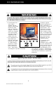
FIELD-READY Glider 21 User Manual Z Microsystems
FCC INFORMATION 1. Use the power and video cables supplied with the Glider to help prevent interference with radio and television reception. The use of cables and adapters may cause interference with electronic equipment in the vicinity of this unit. protection against harmful interference in when equipment is operated in commercial environments.
TABLE OF CONTENTS STARTING POINT Shipment Contents About User Manual System Requirements Features Product Description Tools Required for Installation Precautions 4 4 4 4 4 5 6 6 INSTALLATION 7 Slide Removal 7 Install The Slides In Cabinet Frame 8 Installation Test 10 Final Adjustments 10 Install Cables 11 SETUP Setting Up Glider 12 12 PROTECTOR REMOVAL 14 OPERATIONS Cable Connections Turn On Power Display Panel Controls Menus 15 15 15 16 18 3 Doc# 27-0017UM Issued 08/03 Rev 1.
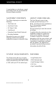
STARTING POINT Congratulations on selecting a rugged field-ready Glider, the most advanced flat panel display available. SHIPMENT CONTENTS ABOUT USER MANUAL The Glider shipping box contains the following: The User Manual comes in two formats: printed hardcopy or CDROM. This Manual is also available on the Z Microsystems website (www.zmicro.com).
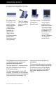
STARTING POINT PRODUCT DESCRIPTION The Glider is an advanced spacesaving drawer mount high-end rugged liquid crystal display. The Glider can be oriented for a portrait format. The LCD display can quickly swing up into a reading position. The unique Glider design allows flat panels up to 21.3” to fold into a 2U (3.5”) drawer space in standard 19” racks and transit cases. Specially designed quickrelease locks hold the compact folded Glider securely in place during storage.
STARTING POINT TOOLS REQUIRED FOR INSTALLATION Required Tools and Equipment: • Flathead screwdriver with about 10" shaft. • Phillips screwdriver with about 10" shaft. WARNING: To avoid shock hazard: • Adjustable wrench or box wrenches. • Do not remove the covers around the Glider. • Do not connect or disconnect the Glider during an electrical storm. • The power cord plug must be connected to a properly wired and grounded power outlet.
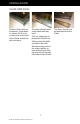
INSTALLATION SLIDE REMOVAL With the Glider laid on a workbench, press down to release the Z-Locks on each side of the front of the Glider to slide the side rails back. The slide rails will reach a stop about half way back. This is a safety stop to prevent the Glider from sliding out too far while mounted in the rack. Simultaneously press in the safety catches on each slide rail and slide the side rails all the way off the back of the Glider. 7 Doc# 27-0017UM Issued 08/03 Rev 1.
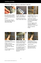
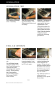
INSTALLATION INSTALL THE SLIDES IN CABINET FRAME Each slide unit includes the slide rail, the front ZLock mount and the rear mount. The top notch of the ZLock must align with the slide rail top ridge. As seen from this reverse view, align the slider into the Z-Lock bracket grooves so all three screw holes show. On the front of the cabinet frame, use three Phillips screws and washers per side to secure the right and left Z-Lock mounts holding the sliders.
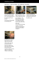
INSTALLATION INSTALL THE GLIDER IN CABINET FRAME The Glider slides should move in and out easily. If not, check alignment of the slider and Z-Lock mount. Pull the two Glider slides out until they lock. Hold the Glider on each side over the back set of rollers, with the front into your stomach. The Glider MUST be level. This step may best be done with two people, one on each side of the slide rails.
INSTALLATION INSTALLATION TEST The Glider should easily close completely. Slide the Glider in and out several times. The Glider should slide in and out easily. Because of variances in cabinet frames, there may need to be some adjustments of the Glider slide system for best fit and movement of the Glider in and out. If the Glider binds when rolling in and out, perform the following procedures. FINAL ADJUSTMENTS Slide the Glider partially out.
INSTALLATION INSTALL CABLES NOTE: Be sure the AC supply is properly grounded. WARNING: Be sure all electrical power to the cabinet is off before connecting any of the cables. WARNING: There is a key guide for alignment on the cables. Be sure the cable plug and receptacles are aligned properly using the key guide. Misalignment can cause short circuiting. The power supply is mounted on the back of the Glider tray. Be sure the power plug going in to the power supply is screwed all the way in.
SETUP SETTING UP GLIDER The outer Z-lock bracket fits snuggly against the female Z-lock bracket attached to the cabinet frame. With both hands, press both the Z-Locks down. Slide the Glider all the way out to the safety stop. If your unit is equipped with lock down features, lift and slide the two display lock knobs at the back of the display to the open or inward positions. This allows the display top to be lifted from its storage position. Push down on the latch at the base of the display.
SETUP SETTING UP GLIDER The display can be left in the vertical position or tilted back. The display can be rotated clockwise to angled positions. The Glider can be slid back until the back of the display almost touches the cabinet. 13 Doc# 27-0017UM Issued 08/03 Rev 1.0 The display can also be moved into the horizontal position. The control knobs will be on the bottom.
PROTECTOR REMOVAL The Protective Outer Shield (optional equipment) is intended to protect the surface of the screen from damage while in transit or while stowed. The display protector is not intended to be used while the display is in operation. To remove the display protector, do the following: Rotate the display to the horizontal position, with the controls on the bottom. Move the display protector release button (located above the display) up.
OPERATIONS CABLE CONNECTIONS NOTE: Connecting to nonstandard systems will require an adapter. To obtain a video adapter, contact Customer Services at Z Microsystem, Inc. NOTE: Make sure the DC connector is plugged in seated properly on the back side of the display head. TURN ON POWER Turn on the power switch on the back of the display. The unit is on when the straight line side is depressed. The unit is off when the circle side is down.
OPERATIONS DISPLAY PANEL CONTROLS The controller features push-button controls on the lower front of the display screen to adjust the brightness of the display, to change the image positioning on the screen, and to refine the screen image. To complete the setup of the display, use the following controls to fine tune the image on the screen: Z : The Z button is used to switch between available channels. NOTE: Current configuration holds only one channel.
OPERATIONS The three LED lights on the right of the control panel are labeled A, B and C. Their lighted functions are: A — VIDEO A green — VIDEO A is selected B — VIDEO B (green) green — VIDEO B is selected If A & B are both green, it indicates the Channel Auto Switching function is selected.
OPERATIONS MENUS To access the onscreen display main menu, press the menu button on the front of the panel. All Glider functions are controlled using the Main Menu’s subtopics. These submenus can be accesssed using the Up and Down buttons on the display panel. See sections below for specifics regarding the submenus. Main Screen Picture Adjust Use the Up and Down buttons to highlight the “Picture Adjust” option. Press the “Menu” button to access the submenu.
OPERATIONS Main Screen Graphics Mode Use the Up and Down buttons to highlight the “Graphics Mode” option. Press the “Menu” button to access the “Graphics Mode” submenu. This submenu is used to adjust the positioning of the image pixels within the screen. Use the Left and Right buttons to adjust the following modes: Horz Coarse, Horz Fine, H Pos, and V Pos. Press “Exit” to return to the Main Menu. The new adjustments will be applied automatically.
OPERATIONS Main Screen Information Use the Up and Down buttons to highlight the “Information” option. Press the “Menu” button to access the “Information” submenu. Within this submenu, video mode resolution, the refresh rate, the sync mode, and the firmware version installed on the unit are displayed. Main Screen Configuration Use the Up and Down buttons to highlight the “Configuration” option. Press the “Menu” button to access the “Configuration” submenu.
DISPLAY HEAD REMOVAL WARNING: Be sure all electrical power is turned off to the Glider before proceeding. To remove the Glider display head, follow these steps: Rotate the display to the horizontal position. On the back of the display, disconnect the power cable. Disconnect the host serial cable. Disconnect the video cable. On the back of the display, press the mounting arm button to release the display head locking bar. Swing the display locking bar out.
MAINTENANCE CLEAN MONITOR WARNING: Be sure to turn off the power before performing any maintenance on the monitor. WARNING: To avoid risk of electric shock, DO NOT dissemble the monitor cabinet. User maintenance is restricted to cleaning as explained here. • Gently wipe the covers and the screen with a soft cloth. • Remove finger marks and grease with a damp cloth and mild detergent or alcohol. DO NOT use solvents or abrasives.
DISPLAY STOWAGE CLOSE GLIDER The following describes closing and stowage of the Glider in the cabinet. Pull the Glider all the way out. Tilt the display head back. From the landscape position, rotate the display to the vertical position. Make sure there is enough room to lower the top of the display head without hitting the cabinet. VER Y IMPORT ANT VERY IMPORTANT Rotate the display locking latch counterclockwise to release the side lock linkage.
DISPLAY STOWAGE CLOSE GLIDER The display latch has now locked the side linkage. Lower the pivot latch into its recepticle. Slide the Glider into the frame until the Z Locks snap into the closed, secure position. 24 Doc# 27-0017UM Issued 08/03 Rev 1.0 Slide the two display locking bolts at the back of the display to the closed position to secure the display.
TROUBLESHOOTING NO IMAGE ON MAIN DISPLAY If there is no image on the main screen, a signal will appear on the screen that states, “No Input, Check Cable”. If the cable from the computer to the display is secure, determine the color of the standby LED and follow the appropriate procedure below. BLACK Cause: If the standby LED is black, there is no power to the unit. Recovery: • Ensure the power cable is plugged into the source. • Connect the power cable to the AC outlet. Ensure the AC outlet is active.
SPECIFICATIONS SPECIFICATIONS Display size 21.3 Inch (432.0 mm x 324.0 mm) Pixels 1600 x 1200 Colors 16.7 Million Contrast Ratio 400:1 Luminescence 250 cd/m2 (max) Interface 2 Ch. LVDS Response Time Rising 20 msec, Falling 15 msec Backlight 6 CCFL Viewing Angle 80/80 Control Control Panel or SoftMenu Power Power Consumption 80 W Power Supply 85-264 VAC @ 47-63 Hz, 400 Hz, 1A Cabling Display Cable 6’ cable, optional Power Cable 6’ cable, IEC Total Packaging Size 3.
APPENDIX SUPPORT If you are unable to correct any problem yourself, contact Z Microsystems at: (858) 657-1000 Fax: (858) 657-1001 Website: www.zmicro.com Before calling, please have available as much of the following information as possible: 1. Model and serial number from the label on the monitor 2. Purchase Order number 3. Description of problem 4. Computer type and model 5. System configuration (hardware fitted, etc.) NOTE: If possible, stay by the computer.
APPENDIX REPLACING PARTS If the Z Microsystems Technical Support Engineer determines that the product needs to be replaced, a Customer Service Representative will issue a Return Material Authorization (RMA) number and return address. A RMA number is required to return a product to Z Microsystems, regardless of the reason for the return. The following information is required when returning Z Microsystems products: 1. Model number 2. Serial number 3. Date of purchase 4.
APPENDIX MECHANICAL OUTLINE DRAWINGS 29 Doc# 27-0017UM Issued 08/03 Rev 1.
APPENDIX 30 Doc# 27-0017UM Issued 08/03 Rev 1.
APPENDIX 31 Doc# 27-0017UM Issued 08/03 Rev 1.
APPENDIX 32 Doc# 27-0017UM Issued 08/03 Rev 1.
APPENDIX 33 Doc# 27-0017UM Issued 08/03 Rev 1.
Z Microsystems, Inc. 5945 Pacific Center Blvd., Suite 505 San Diego, CA 92121 Phone: (858) 657-1000 Fax; (858) 657-1001 Website: www.zmicro.com Copyright 1999 Z Microsystems, Inc.