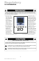
FIELD-READY FIELD-READY G L I D E R 20 User Manual ZZMicrosystems Microsystems Doc# 27-0006UM Issued 11/00 Rev 1.
Regulatory FCC INFORMATION 1. Use the power and video cables supplied with the Glider to help prevent interference with radio and television reception. The use of cables and adapters may cause interference with electronic equipment in the vicinity of this unit. interference in when equipment is operated in commercial environments.
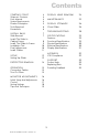
Contents STARTING POINT Shipment Contents User Manual System Requirements Product Description Tools Required Precautions 4 4 4 4 5 6 6 INSTALL RAILS Slide Removal Install The Slides In Cabinet Frame Install The Glider In Frame Installation Test Final Adjustments Install Cables 7 7 8 9 10 10 11 SETUP Setting Up Glider 12 12 PROTECTOR REMOVAL 14 OPERATION Connecting Cables Turn On Power 15 15 15 MONITOR ADJUSTMENTS Initial Setup And Adjustments Control Saving Settings Tips And Techniques 16 16 17 1
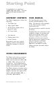
Starting Point Congratulations on selecting a rugged field-ready Glider -- the most advanced flat panel display available. SHIPMENT CONTENTS USER MANUAL The Glider shipping box contains the following: The User Manual comes in two formats: printed hardcopy or CDROM. This Manual is also available on the Z Microsystems website (www.zmicro.com).
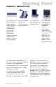
Starting Point PRODUCT DESCRIPTION The Glider is an advanced spacesaving drawer mount high-end rugged liquid crystal display. The LCD display can quickly swing up into a reading position. The Glider can be oriented for a portrait format. The unique Glider design allows flat panels up to 20.1 to fold into a 2U (3.5) drawer space in standard 19 racks and transit cases. Specially designed quickrelease locks hold the compact folded Glider securely in place during storage.
Starting Point TOOLS REQUIRED Required Tools and Equipment. Flathead screwdriver with about 10" shaft. Phillips screwdriver with about 10" shaft. Adjustable wrench or box wrenches. WARNING: To avoid shock hazard: Do not remove the covers around the Glider. Do not connect or disconnect the Glider during an electrical storm. The power cord plug must be connected to a properly wired and grounded power outlet.
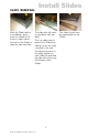
Install Slides SLIDE REMOVAL With the Glider laid on a workbench, press down to release the ZLocks on each side of the front of the Glider to slide the side rails back. The slide rails will reach a stop about half way back. This is a safety stop to prevent the Glider from sliding out too far while mounted in the rack. Simultaneously press in the safety catches on each slide rail and slide the side rails all the way off the back of the Glider. 7 Doc# 27-0006UM Issued 11/00 Rev 1.
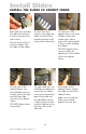
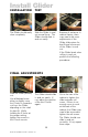
Install Slides INSTALL THE SLIDES IN CABINET FRAME Each slide unit includes the slide rail, the front Z-Lock mount and the rear mount. The top notch of the ZLock must align with the slide rail top ridge. On the rear of the cabinet frame, use three Phillips screws to loosely secure the right and left rear slide mounts to the cabinet frame. DO NOT tighten these screws fully. As seen from this reverse view, align the slider into the Z-Lock bracket grooves so all three screw holes show.
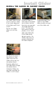
Install Glider INSTALL THE GLIDER IN CABINET FRAME The Glider slides should move in and out easily. If not, check alignment of the slider and Z-Lock mount. Pull the two Glider slides out until they lock. Hold the Glider on each side over the back set of rollers, with the front into your stomach. The Glider MUST be level. This step may best be done with two people, one on each side of the slide rails.
Install Glider INSTALLATION TEST The Glider should easily close completely. Slide the Glider in and out several times. The Glider should slide in and out easily. Because of variances in cabinet frames, there may need to be some adjustments of the Glider slide system for best fit and movement of the Glider in and out. If the Glider binds when rolling in and out, perform the following procedures. FINAL ADJUSTMENTS Slide the Glider partially out.
INSTALL CABLES NOTE: The glider has an ACDC converter built into the power supply. Be sure the AC supply is 110 vac and properly grounded. WARNING: Be sure all electrical power to the cabinet is off before connecting any of the cables. WARNING: There is a key guide for alignment on the cables. Be sure the cable plug and receptacles are aligned properly using the key guide. Misalignment can cause short circuiting. The power supply is mounted on the back of the Glider tray.
Setup SETTING UP GLIDER The outer Z-lock bracket fits snuggly against the female Z-lock bracket attached to the cabinet frame. With both hands, press both the Z-Locks down. Slide the Glider all the way out to the safety stop. Lift and slide the two display lock knobs at the back of the display to the open or inward positions. This allows the display top to be lifted from its storage position. Push down on the latch at the base of the display.
SETTING UP GLIDER The display can be left in the vertical position or tilted back. The display can be rotated clockwise to angled positions. The Glider can be slid back until the back of the display almost touches the cabinet. 13 Doc# 27-0006UM Issued 11/00 Rev 1.0 The display can also be moved into the horizontal position. The control knobs will be on the bottom.
Protector Removal The display protector is intended to protect the surface of the screen from damage while in transit or while stowed. The display protector is not intended to be used while the display is in operation. To remove the display protector, do the following: Rotate the display to the horizontal position, with the controls on the bottom. Move the display protector release button (located above the display) up. While holding up the display protector button, slide the protector to the right.
Operation CONNECTING CABLES NOTE: Connecting to non-standard systems will require an adapter. To obtain a video adapter, contact Customer Services at Z Microsystem, Inc. NOTE: Incorrect cable connections may result in irregular operation, damage display quality/components of the LCD module and/or shorten the modules life. Always consult the computer system manual. Verify the systems compatibility to ensure proper operation.
Monitor Adjustments INITIAL SETUP AND ADJUSTMENTS The Glider features pushbutton controls on the lower front of the display screen to adjust the brightness of the display, to change the image positioning on the screen, and to refine the screen image.
Monitor Adjustments This section explains how to use the Glider control buttons to adjust the clarity of the display and image position on the screen. In particular it discusses: The function of each of the pushbutton controls. How to reset previously saved settings or return to factory settings. Tips and techniques.
Monitor Adjustments NOTE: The H Wd parameters must be properly set in order for the Clock settings to have their desired effect. The Clock settings are the final fine tuning adjustments. V Pos Moves the screen image up or down. Clock The Clock controls move the sampling points left or right while maintaining a fixed distance between samplings. These adjustments ensure that the sampling occurs at the peak of the input video signal (i.e.
The Glider can store screen settings for multiple resolutions, which is especially useful when it is used with a graphics card that supports a range of resolutions. The resolutions supported by the Glider include: 1280 x 1024, SXVGA 1024 x 768, XGA 832 x 624, Mac 800 x 600, SVGA 640 x 480, VGA 720 x 400, VGA Tet 640 x 400, PC9801 TIPS AND TECHNIQUES Graphics cards create a wide variety of screen resolutions.
Monitor Adjustments Step 1: Power Up After the installation instructions have been followed: Turn on power to the computer/ workstation. Turn on power to the Glider. The Glider will then: Illuminate the Power indicator on the front panel. Perform self tests. Search for and automatically determine the frequencies and sync type of the incoming video signals. Illuminate the stby indicator on the front panel while powering up and searching for proper sync signals.
Monitor Adjustments Step 3: Width Adjust Horizontal This is the critical step to ensure a crisp screen image. For a Sharp display, you must adjust the image so that it fits precisely within the boundaries of the screen. To adjust the horizontal width: 1. Press the SELECT button until the H Wd indicator is illuminated. Alternately press the and buttons to size the screen image to the exact width of the display.
Monitor Adjustments Step 4: Adjust Horizontal Po s i t i o n Press the SELECT button until the H Pos indicator is illuminated, then use the and buttons to adjust the horizontal position of the screen left or right to center the screen image. Helpfut Hint: When the screen is properly adjusted, the left and right sides of the screen will line up precisely with the left and right sides of the panel.
To adjust the screen for the best possible display, try the following: Press the and buttons until you have a universally fuzzy screen. Count the number of button presses for the screen to go from fuzzy to clear to fuzzy again. NOTE: If at this point the screen image is not crisp, repeat Steps 2-4. Divide the number of presses by two and press the button that many times to precisely end up at the clearest setting.
Display Head Removal WARNING: Be sure all electrical power is turned off to the Glider before proceeding. To remove the Glider display head, follow these steps: Rotate the display to the horizontal position. On the back of the display, disconnect the power cable. Disconnect the video cable next to the power cable. On the back of the display, press the mounting arm button to release the display head locking bar. Swing the display locking bar out.
CLEAN MONITOR WARNING: Be sure to turn off the power before performing any maintenance on the monitor. WARNING: To avoid risk of electric shock, DO NOT dissemble the monitor cabinet. User maintenance is restricted to cleaning as explained here. Gently wipe the covers and the screen with a soft cloth. Remove finger marks and grease with a damp cloth and mild detergent. DO NOT use solvents or abrasives. Never use flammable cleaning material to clean the monitor or other ectrical apparatus.
Display Stowage CLOSE GLIDER The following describes closing and stowage of the Glider in the cabinet. Pull the Glider all the way out to the stop. Tilt the display head back. From the landscape position, rotate the display to the vertical position. Make sure there is enough room to lower the top of the display head without hitting the cabinet. VERY IMPORTANT Rotate the display pivot latch counter-clockwise to release the side lock linkage.
Display Stowage CLOSE GLIDER Lower the pivot latch into its recepticle. Slide the two display linkage locks at the back of the display to the closed position to secure the display. 27 Doc# 27-0006UM Issued 11/00 Rev 1.0 Slide the Glider into the frame until it snaps into the closed, secure position.
Troubleshooting NO IMAGE ON DISPLAY Flip the power switch to on. The circle should be down. Connect the power cable to a 110 vac outlet, which is turned on. Connect the video cable to the computer. Be sure the computer is on and operating. Make sure the power cable to the back of the Glider is plugged in all the way. Make sure the video cable to the back of the Glider is plugged in all the way. Make sure the power cable from the Glider to the back of the display head is plugged in all the way.
FEATURES Large Display Area Multi-Scan/Sync Capability Wide Viewing Angle Small Package Outline Full Color High Contrast Ratio FUNCTIONAL SPECIFICATIONS Supported Resolutions 640 x 400* 720 x 400* (text) 640 x 480 800 x 600* 832 x 624* 1024 x 768* 1280 x 1024 * Interpolated Resolutions: When resolutions are shown that are lower than the pixel count of the LCD module, text may appear choppy or lines may appear to be bold.
Specifications PHYSICAL SPECIFICATIONS Display Dimensions Height 16.7 in (42.4 cm) Width 20.0 in (50.8 cm) Rack Dimensions Height 3.5 in (8.9 cm) Width 19.0 in (48.3 cm) Depth 26.3 in (66.8 cm) Display Weight 23 lbs (10.4 kg) Rack Weight 15 lbs (6.
DISPLAY SPECIFICATIONS Display Area Horizontal 15.7 in (39.9 cm) Vertical 12.6 in (32.0 cm) Diagonal 20.1 in (50 cm) Number of Pixels 1280 x 1024, RGB Vertical Stripe Pixel Pitch Horizontal 0.312 mm Vertical 0.312 mm Contrast Ratio 150:1 (typical) Total Viewing Angle 160 degrees (horizontal and vertical) Response Time 130 ms (maximum) black to white Luminance 150 cd/m2 (typical) Display Colors Full-color (millions) 31 Doc# 27-0006UM Issued 11/00 Rev 1.
Appendix Y2K COMPLIANCE Z Microsystems has achieved full Y2K Compliance. In late 1997, the companys senior management assigned a Y2K Project Team that consists of a cross-functional representation from information technology, procurement, manufacturing, test and development, finance, general affairs, engineering, marketing and facilities organizations to address the Year 2000 issues.
Support FURTHER HELP If you are unable to correct any problem yourself, contact: Z Microsystems at: (858) 657-1000 Fax: (858) 657-1001 Website: www.zmicro.com Before calling, please have available as much of the following information as possible: 1. Model and serial number from the label on the monitor. 2. Purchase Order number. 3. Description of problem. 4. Computer type and model. NOTE: If possible, stay by the computer.
Support REPLACING PARTS If the Z Microsystems Technical Support Engineer determines that the product needs to be replaced, a Customer Service Representative will issue a Return Material Authorization (RMA) number and return address. A RMA number is required to return a product to Z Microsystems, regardless of the reason for the return. The following information is required when returning Z Microsystems products: 1. Model number 2. Serial number 3. Date of purchase 4.
Z Microsystems, Inc. 5945 Pacific Center Blvd., Suite 509 San Diego, CA 92121 Phone: (858) 657-1000 Fax; (858) 657-1001 Website: www.zmicro.com Copyright 1999 Z Microsystems, Inc. All Rights Reserved Doc# 27-0006UM Issued 11/00 Rev 1.