Command Console SL
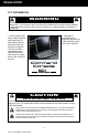
REGULATORY FCC INFORMATION WARNING TO PREVENT FIRE OR SHOCK HAZARDS, DO NOT EXPOSE THIS UNIT TO RAIN OR MOISTURE. ALSO, DO NOT USE THIS UNIT’S POLARIZED AS PLUG WITH AN EXTENSION CORD RECEPTACLE OR OTHER OUTLETS UNLESS ALL THREE PRONGS CAN BE FULLY INSERTED 2. Changes or modifications not expressly approved by Z Microsystems could void user’s warranty. 1. Use the power and video cables supplied with the product to help prevent interference with radio and television reception.
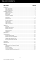
TABLE OF CONTENTS SECTION PAGE Introduction ........................................................................................................................4 About This Manual ....................................................................................................4 Safety Precautions....................................................................................................4 Product Description ....................................................................................
INTRODUCTION ABOUT MANUAL This Manual is also available on the Z Microsystems website (www.zmicro.com). We recommend you read this manual carefully and follow the instructions in the Installation chapter for verification of system functions and control settings. Safety Precautions DANGER: To avoid shock hazard: • Do not remove the covers around the Command Console • Do not connect or disconnect the Command Console during an electrical storm.
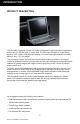
INTRODUCTION PRODUCT DESCRIPTION The ultra-slim Command Console SL model is designed for rapid deployable applications and fits any 19” RETMA rack or transit case. The Command Console SL model brings together a 19” (1280 x 1024) flat panel display, a full size water tight keyboard and track ball all in only 1.75” (1U) height. The Command Console SL model also solved cable retracting problems.
INSTALLATION SHIPMENT CONTENTS Ensure all of the following parts are included in the package received from Z Microsystems. Verify all parts have not been damaged during shipment. If any of the parts are missing or damaged, immediately contact Z Microsystems Customer Service at 858-657-1000. • Command Console unit attached to the mounting plate • Power Cable • User Manual • Video Cable • Serial Cable Required Tools • Rack-mounting hardware • Phillips screwdriver, 2 pt.
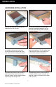
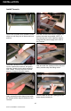
INSTALLATION HARDWARE INSTALLATION Remove the outer rack mounting slide channels from the Console. On the rear unscrew the left and right rear rack mounting brackets to free up the outer rack mounting slide channels from the Console. Press the spring loaded Z Locks towards the middle to release the outer rack mount slide channels and at the same time slide the rack mounting block back. Slide the channels back until they stop about half way back.
INSTALLATION Install Rails Both outer rack mount slide channels should be separated at this time. The slide channels come pre-assembled to fit a 24” deep rack. To fit a 25” rack, the rear mounting bracket can be repositioned as shown here.
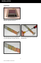
INSTALLATION To mount the channels on the front of the RETMA rails (in most cases), use two 1032 Phillips screws... on each side to secure the Z-Lock mounts. Be sure to press the slide rail flat against the RETMA rail as you tighten the screws. On the rear of the cabinet frame, also use two Phillips screws on each rail to secure. On the slide rails, using a screwdriver and wrench, tighten the slide extension rail screw. Repeat on each side.
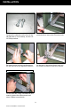
INSTALLATION Install Console Pull the two Console inner members of the slides out until they lock in the second lock position. Hold the Console with the front toward you and as horizontal as possible. NOTE: In the next step, be sure to carefully support and guide the power supply at the rear of the Console. Guide the Console’s inner slide member into the middle slide member, and gently slide the Console into the slide assembly until it stops. This may require a second person to support the power supply.
INSTALLATION Secure the power supply to the right rear of the Console, using #8-32 x .75”L screws. Secure the left side also, as shown above.
INSTALLATION Z Locks Description The mechanical principle of the Z Locks is similar to spring-loaded dead bolts. Two stainless steel compression springs in each lock press against the bolt so that it will not come loose even with substantial force.
INSTALLATION Setup Console To pull out the Command Console, place your hands so that your palms face upwards. Your thumb should be on the tab of the lock and the first three fingers are under the pull-out bar. Push the tabs towards each other and with your fingers pull out the Console until the first safety catch stops the slide action. Press both slide catches inward and pull the Console out. Allow the Console to stop at the second catch.
INSTALLATION ...into viewing position. Push unit into the first locking position of the slides.
INSTALLATION Close Console To fold down the Console, pull out the Console fully from the rack Stand slightly to the right of the unit and lower the panel down on its back into the tray. With the right hand pull back on the tab of the lock down mechanism. Lay the panel fully down and release so that the panel becomes locked in the horizontal position. Disengage the slide lock from the second slide lock position. Push the Console into the first slide lock position.
OPERATIONS CABLE CONNECTIONS The connections panel may vary due to non-standard configurations. The following configuration shows both PS2 and USB cable connections on one sample. In most cases, the Command Console will utilize just one of these connector types. PS2 KEYBOARD TRACKBALL POWER VIDEO HOST SERIAL USB (TYPE B) KEYBOARD , TRACKBALL POWER UP When the Command Console is connected, apply power and ensure the main screen appears.
OPERATIONS DISPLAY PANEL CONTROLS The Command Console features push-button controls on the lower front of the front bezel. To setup the display, use the following controls to fine tune the image on the screen: NOTE: The following procedures are written for setup using the buttons on the display panel. See the “SoftMenus” section of this manual for remote setup.
OPERATIONS DISPLAY PANEL SETUP This following section explains how to use the control buttons to adjust image clarity and image position on the screen. In particular it discusses: • The function of each of the push-button controls • How to reset previously saved settings or return to factory settings • Tips and techniques NOTE: The control buttons allow the user to control backlight operations; to store settings, and to revert to factory-saved settings.
OPERATIONS ONSCREEN MENUS To access the onscreen display main menu, press the menu button on the front of the panel. The Command Console’s functions are controlled using the Main Menu’s subtopics. These submenus can be accessed using the Up and Down buttons on the display panel. See sections below for specifics regarding the submenus. Main Screen Picture Adjust Use the Up and Down buttons to highlight the “Picture Adjust” option. Press the “Menu” button to access the submenu.
OPERATIONS Main Screen Graphics Mode Use the Up and Down buttons to highlight the “Graphics Mode” option. Press the “Menu” button to access the “Graphics Mode” submenu. “Graphics Mode” is used to adjust the positioning of the image. Use the Up and Down Keys to highlight the desired option. Use the Left and Right buttons to adjust the following modes: Horz Coarse, Horz Fine, H Pos, and V Pos. The “Horz Coarse” option adjusts the horizontal width of the image.
OPERATIONS Main Screen Information Use the Up and Down buttons to highlight the “Information” option. Press the “Menu” button to access the “Information” submenu. Within this submenu, view the video mode resolution, the refresh rate, and the sync mode. Press “Exit” to return to the Main Menu. The Firmware Version and Build Date are also available on this screen.
OPERATIONS KVM Control (see KVM on screen on previous page): Toggles ON/OFF to apply or remove preset KVM command features. The preset commands are programmed as alternate functions of the firmware buttons on the front of the panel. For predefining the KVM character strains, please refer to SoftMenu instructions regarding KVM Control. 22 Doc# 27-0032UM Rev A Issued 07/05 NOTE: When the KVM Control is turned ON, the Main Menu requires the button be held down for extended length of time to be made active.
OPERATIONS SOFTMENUS™ SoftMenus™ are control panel dialog screens accessed from the host computer, allowing flexibility where positioning and environmental demands are a concern. In order to access the SoftMenu™ features, the host serial port must be accessed at the rear of the Command Console. The Command Console must be connected to the computer and software must be installed.
OPERATIONS Monitor SoftMenus™ The Monitor SoftMenu™ dialog screen allows the operator to adjust Channel Configuration activity, Default settings, Auto Adjust, Brightness and Contrast characteristics, Coarse and Positioning range, and Color Balancing of the main screen image in one easy-to-use menu. Monitor Screen “Factory Default” and “Auto Adjust” Buttons To adjust the monitor screen settings, the “Monitor” tab must be active.
OPERATIONS MENU BAR The SoftMenus’ menu bar also includes the “Edit” and “Tools” drop-down menus. Left click on any of the following drop-down menus: File Load previously saved display settings and save settings in the “File” drop-down menu. Multiple users may wish to alter the settings individually with this feature. Edit Manage, add, and remove the ports used by SoftMenus for communication with the “Edit” drop-down menu.
OPERATIONS Tools Tools are available to further enhance the SoftMenus. KVM Setup can be controlled from this location. See the next page for details on the KVM Control option. Help Utilize the software “Help” settings to read about the version of the unit, as well as information about Z Microsystems. HOT KEYS Hot Keys are only available on the Linux and Windows versions of Z Microsystems’ software. The following combinations of “hot” keys have been customized for ease of use of the Command Console.
OPERATIONS KVM Control The SoftMenus KVM Control feature enables the display to communicate with the KVM over the serial port. The ASCII string assignments can only be configured through SoftMenus. To assign or alter the ASCII strings, click on the SoftMenus’ Tools drop-down menu. Left click on the “KVM Setup” option and the following screen will appear: The button images map to the physical buttons on the display panel.
MAINTENANCE MAINTAINING THE COMMAND CONSOLE WARNING: Be sure to turn off the power before you perform any maintenance on the monitor. WARNING: To avoid risk of electric shock, do not disassemble the monitor cabinet. Users cannot service the monitor. User maintenance is restricted to cleaning as explained below. CLEANING THE COMMAND CONSOLE Unplug the Command Console from the power outlet before cleaning. • To clean, lightly dampen a soft, clean cloth with water or mild detergent.
TROUBLESHOOTING TROUBLESHOOTING THE COMMAND CONSOLE No Main Display Image If there is no image on the main screen, a signal will appear on the screen that states, “No Input, Check Cable”. If the cable from the computer to the display is secure, determine the color of the standby LED and follow the appropriate procedure below. Black Problem: If the standby LED is black, there is no power to the unit. Recovery: • Ensure the power cable is plugged into the source. • Connect the power cable to a AC outlet.
TROUBLESHOOTING Display Image Has Vertical Bars If the main image begins to display vertical bars, adjust the “Horz Coarse”. From the Main Menu, use the Up and Down buttons to highlight the “Graphics Mode” option. Press the “Menu” button to access the “Graphics Mode” submenu. Use the Left and Right buttons to adjust the screen until the number of bars is reduced. Continue adjusting one step at a time until the bars are no longer visible.
SCHEMATICS MECHANICAL OUTLINE FOR COMMAND CONSOLE 31 Doc# 27-0032UM Rev A Issued 07/05
Doc# 27-0032UM Rev A Issued 07/05 2.561 17.853 5.908 24.000 TO 25.00 14.192 29.317 9.155 17.046 18.
SCHEMATICS REAR VIEW PS/2 VERSION PS/2 TRACKBALL PS/2 KEYBOARD REAR VIEW USB Version VIDEO USB (TYPE B) HOST SERIAL KEYBOARD , TRACKBALL .100 .100 18.102 1.250 1.740 .245 18.806 R.100 BACK OF RACK FRONT OF RACK 3.059 2.
1st Locking Position FRONT OF RACK 8.09 17.88 14.
2nd Locking Position FRONT OF RACK 3.57 R15.0 17.59 27.
REPLACEMENTS REPLACING PARTS If the Z Microsystems Technical Support Engineer determines that the product needs to be replaced, a Customer Service Representative will issue a Return Material Authorization (RMA) number. An RMA number is required to return a product to Z Microsystems, regardless of the reason for the return.
APPENDIX SPECIFICATIONS FOR COMMAND CONSOLE The Command Console is designed to host a choice of LCD’s from several manufacturers based upon customer requirements. The specifications unique to each particular LCD vary from manufacturer to manufacturer. These particular specifications are available through our sales department. General Display Specifications Display size 19 Inch Resolution Up to 1280 x 1024 Color Palette 16.7 Million Contrast Ratio 700:1 (typ) Pixel Pitch .294 mm x .
APPENDIX Non-Op Temp -40° to 70° C Humidity 5%-95% Non-Condensing Operating Altitude Up to 10,000 ft Non-Op Altitude Up to 40,000 ft Vibration MIL-STD-167 Shock MIL-STD 810E (Method 516) 30 g’s MIL-S-901D (in isolated rack) Sand and Dust 5.5 MPH for 25 mins (display bezel, keyboard and trackball only) Drip MIL-STD-810E (display bezel, keyboard and trackball only) Fungus Non-Nutrients/Contaminants Reliability MTBF Display: 20,000 hrs w/ backlight change at 10,000 hrs.
APPENDIX WARRANTIES Standard Warranty -no charge- Z Microsystems’ one-year Standard Warranty includes a 90-day AirSpare Service Plan. This means that if any standard Z Microsystems’ product fails within the first 90 days after shipping, the customer will receive a new replacement. All non-standard* products are covered for one year under Z Microsystems’ Standard Warranty that includes free parts and labor. However, the 90-day AirSpare Plan can be purchased as an additional option for non-standard products.
APPENDIX Z Extended Warranty Z Microsystems’ Extended Warranty Plan provides one and two year extended warranty options under which a Standard Warranty is extended from the end of the first year of the Standard Warranty period. The One-Year Extended Warranty period will begin on the day the Standard Warranty expires and the Two-Year Extended Warranty begins when the One-Year Extended Warranty expires.
APPENDIX Z Preferred Warranty Z Microsystems provides a Preferred Service Plan under which Z Microsystems will repair or replace and return a defective product to the customer within one week of Z Microsystems’ receipt of the defective product.
APPENDIX Z Airspare Warranty 365 DAYS Z Microsystems provides an AirSpare Service Plan that will replace a defective product, within the first year of the warranty period, with a new product the following business day.* The AirSpare Service Plan does not cover special order items. A product may be deemed a special order item at the discretion of the Customer Service Department.
APPENDIX Z On-Site Service Z Microsystems also provides on site service and consultation to customers who require Z Microsystems’ technical expertise.
APPENDIX Disclaimer Z Microsystems warrants that every product is free from defects in materials, workmanship and conforms to Z Microsystems’ stringent specifications. Z Microsystems calculates the expiration of the warranty period from the date the product is shipped. This means that the ship date on your invoice is your product ship date unless Z Microsystems informs you otherwise.
APPENDIX CUSTOMER SUPPORT NOTE: For image problems, run AUTO SETUP again before consulting this section. In most cases, AUTO SETUP can fix the problems. See the Auto Setup section for details. NOTE: If possible, stay by the computer. The Z Microsystems Technical Support Representative may wish to go through the problem over the telephone. If you are unable to correct the problem yourself, contact: Z Microsystems at: (858) 657-1000 Fax: (858) 657-1001 Website: www.zmicro.
APPENDIX CUSTOMER FEEDBACK We value feedback on our products, their performance, problems found, and welcome all constructive suggestions. Please send such productive information in writing to: Customer Service Z Microsystems 5945 Pacific Center Blvd., Suite 505 San Diego, CA 92121 or www.zmicro.
APPENDIX COMMAND CONSOLE SERIAL CONTROL ICD The following serial port property settings must be in place in order for the host to have communication with the display. SPEED 19,200 BPS DATA BITS 8 PARITY None STOP BITS 1 FLOW CONTROL None The serial control ICD commands are presented here for the user’s knowledge. The commands are written and controlled by Z Microsystems and are not intended for the customer to use.
APPENDIX Argument No arguments. PBB Description PBB adjusts the blue balance of the main images RGB setting. Argument The allowable range is 0-255 base10. The factory default is 128. PBG Description PBG adjusts the green balance of the main images RGB setting. Argument The allowable range is 0-255 base10. The factory default is 128. PBR Description PBR adjusts the red balance of the main images RGB setting.
APPENDIX PDS Description PDS has the display place all of the settings back to the factory defaults. Argument No arguments. PHC Description PHC adjusts the horizontal coarse setting. Argument The allowable range is 0-255 base10. The factory default is 128. PHF Description PHF adjusts the horizontal fine setting. Argument The allowable range is 0-248 base10. The factory default is 119. PHP Description PHP adjusts the horizontal position of the image. Argument The allowable range is 76-180 base10.
APPENDIX PVP Description PVP adjusts the vertical position of the image. Argument The allowable range is 106-150 base10. The factory default is 128. Non-Standard Command Structure The following commands do NOT use the standard command structure. They are sent “as is” to the controller, succeeded by a carriage return (CR). EPROM SAVE Description EPROM SAVE instructs the controller to store the display settings.
Z Microsystems, Inc. 5945 Pacific Center Blvd., Suite 505 San Diego, CA 92121 Phone: (858) 657-1000 Fax: (858) 657-1001 Website: www.zmicro.com Copyright 2005 Z Microsystems, Inc.