FIELD-READY FIELD-READY FIELD-READY STARGATE 18 User Manual Z ZMicrosystems Microsystems Doc# 27-0005UM Issued 11/00 Rev 1.
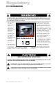
Regulatory FCC INFORMATION 1. Use the power and video cables supplied with this equipment to help prevent interference with radio and television reception. The use of cables and adapters may cause interference with electronic equipment in the vicinity of this unit. 56)4/)6- & 2. This equipment has been tested and found to comply with the limits for Class A digital devices, pursuant to certain limits imposed 2 Doc# 27-0005UM Issued 11/00 Rev 1.0 by Part 15 of the FCC rules.
Contents STARTING POINT Shipment Contents User Manual Product Description Tools Required Precautions 4 4 4 5 6 6 MAINTENANCE Clean Front Panel 16 16 TROUBLESHOOTING 17 SPECIFICATIONS 18 INSTALL STARGATE 7 PROTECTOR REMOVAL 9 APPENDIX Warranty Y2K Compliance 19 19 22 CONNECTING CABLES 10 POWER UP 10 MONITOR ADJUSTMENTS Initial Setup And Adjustments Controls Saving Settings Tips And Techniques 11 11 12 13 14 SUPPORT Further Help Replacing Parts Providing Feedback 23 23 24 24 3 Doc# 27-00
Starting Point Congratulations on selecting a rugged field-ready StarGate -- the ultra rugged flat display. SHIPMENT CONTENTS USER MANUAL The StarGate shipping box contains the following: The User Manual comes in two formats: printed hardcopy or CDROM. This Manual is also available on the Z Microsystems website (www.zmicro.com).
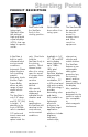
Starting Point PRODUCT DESCRIPTION The rugged lightweight StarGate offers MIL-tailored high-end liquid crystal displays (LCDs) that can adapt to specific needs. Dual locks hold the StarGate firmly in the viewing position. Quick release levers allow it to swing open. The StarGate can be opened all the way for access to storage items and other sensitive equipment. A StarGate is built to easily withstand harsh environmental conditions.
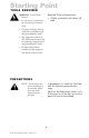
Starting Point TOOLS REQUIRED Required Tools and Equipment WARNING: To avoid shock hazard: Phillips screwdriver with about 10" shaft. Do not connect or disconnect the unit during an electrical storm. The power cord plug must be connected to a properly wired and grounded power outlet. Any equipment to which the unit will be attached must also be connected to properly wired and grounded power outlets The socket outlet shall be installed near the equipment and shall be easily accessible. .
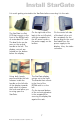
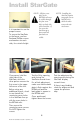
Install StarGate It is worth getting oriented to the StarGate before mounting it in the rack. The StarGate is a flat LCD that mounts on the front of the RETMA rails of a standard 19 rack. The dual locks can be seen on the vertical handle to the left. The display controls are located on the bottom below the display. Using both hands, press and slide the lock releases inside the handle on the left side of the display towards each other to release the locks and allow you to swing open the StarGate.
Install StarGate NOTE: All four screw holes in the RETMA rail must be visible through the four screw holes on both sides of the StarGate. If not, move the StarGate up or down until all four holes are visible. It is important to use the proper screws. To secure the StarGate to the frame, use four Panhead Phillips screws and washers on each side, for a total of eight. One person hold the right side of the StarGate, while the other person secures the first screw in the upper left corner of the unit.
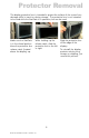
Protector Removal The display protective lens is intended to protect the surface of the screen from damage while in transit or during storage. The protective lens is not intended to be used while the StarGate is in operation, but can be used. Make sure the StarGate is in the closed position. Move the protective lens release catch (located above the display) up. While holding up the release catch, slide the protective lens to the left or right. 9 Doc# 27-0005UM Issued 11/00 Rev 1.
Connecting Cables Connect the AC power cable on the right back side of the StarGate to AC power outlet. The socket outlet shall be installed near the equipment and shall be easily accessible. Connect the power cable on the left back side of the StarGate to the power supply. Be sure the flat part of the connector is facing the back of the StarGate. Connect the power cable from the power supply to the StarGate display. Be sure the flat part of the connector is facing the back of the StarGate.
Monitor Adjustments INITIAL SETUP AND ADJUSTMENTS The StarGate features pushbutton controls on the lower front of the display screen. For adjustments use the following controls to fine tune the image on the screen: 11 Doc# 27-0005UM Issued 11/00 Rev 1.
Monitor Adjustments The StarGate can store screen settings for multiple resolutions, which is especially useful when it is used with a graphics card that supports a range of resolutions. The resolutions supported by the StarGate include: 1280 x 1024, SXVGA 1024 x 768, XGA 832 x 624, Mac 800 x 600, SVGA 640 x 480, VGA 720 x 400, VGA Tet 640 x 400, PC9801 TIPS AND TECHNIQUES Graphics cards create a wide variety of screen resolutions.
Monitor Adjustments Step 1: Power Up After the installation instructions have been followed: Turn on power to the computer/ workstation. Turn on power to the StarGate. The StarGate will then: Illuminate the Power indicator on the front panel. Perform self tests. Search for and automatically determine the frequencies and sync type of the incoming video signals. Illuminate the stby indicator on the front panel while powering up and searching for proper sync signals.
Monitor Adjustments 14 Doc# 27-0005UM Issued 11/00 Rev 1.
Monitor Adjustments NOTE: See Saving Settings earlier in this manual for a complete discussion of this subject. Step 7: The screen settings will automatically be saved as long as the power is maintained for at least five seconds after the last adjustment. 15 Doc# 27-0005UM Issued 11/00 Rev 1.
Maintenance CLEAN FRONT PANEL WARNING: Be sure to turn off the power before performing any maintenance on the StarGate Gently wipe the front panel of the StarGate with a soft cloth. Remove finger marks and grease with a damp cloth and mild detergent. DO NOT use solvents or abrasives. Never use flammable cleaning material to clean the front panel of the StarGate or other electrical apparatus. 16 Doc# 27-0005UM Issued 11/00 Rev 1.
Troubleshooting Power light does not illuminate Check that power cable is properly connected to 110 vac power supply. Check that front panel power switch is on. Check that power switch on back of StarGate display is on. 17 Doc# 27-0005UM Issued 11/00 Rev 1.
Specifications DISPLAY SIZE Display Type Resolution Pixel Configura Video Input Separate sync Horizontal sync Vertical sync Sync on Green Pixel Frequenc Color Palette Contrast Ratio Pixel Pitch Luminance Diagonal Dim. Horizontal Vertical Viewing Angle Control Optical Resp. T Power Consum Power Supply Current 18 - inch AMLC Up to 1280 x 1024 @ 60 Hz RGB Vertical Stripe Analog RGB 0.7Vp-p/75 Ohm Pos. TTL level Positive/Negative Positive/Negative Video 0.
Appendix WARRANTY 1 Year Extended Warranty Extent of Limited Warranty 1. Z Microsystems, Inc. (Z Micro) warrants to the end-user that Z Micro products will be free from defects in materials and workmanship for a specified time after the date of purchase. The duration of this limited warranty is stated above. Certain additional conditions and limitations of Z Micros warranty are stated in the User Guide.
Appendix WARRANTY consumer (for example, Australia and the United Kingdom); Otherwise restrict the ability of a manufacturer to make such disclaimers or impose such limitations; Grant the customer additional warranty rights, specify the duration of implied warranties which the manufacturer cannot disclaim, or not allow limitations on how long an implied warranty lasts. 3. To the extent allowed by local law, the remedies provided in this Warranty Statement are the customers sole and exclusive remedies.
Appendix WARRANTY have your equipment on its way back within 5 days). However, if the damaged equipment has to be serviced by the original manufacturer (Seagate, NEC, for example), it may take longer. Are there any extra costs? The only per incident cost you will incur is Freight In to return the equipment to the factory. Your extended warranty covers all of the costs associated with the repair and the return shipment of the covered equipment.
Appendix Y2K COMPLIANCE Z Microsystems has achieved full Y2K Compliance. In late 1997, the companys senior management assigned a Y2K Project Team that consists of a cross-functional representation from information technology, procurement, manufacturing, test and development, finance, general affairs, engineering, marketing and facilities organizations to address the Year 2000 issues.
Support FURTHER HELP If you are unable to correct any problem yourself, contact: Z Microsystems at: (858) 657-1000 Fax: (858) 657-1001 Website: www.zmicro.com Before calling, please have available as much of the following information as possible: 1. Model and serial number from the label on the monitor. 2. Purchase P.O. 3. Description of problem. NOTE: If possible, stay by the computer. The Z Microsystems Technical Support Representative may wish to go through the problem over the telephone. 4.
Support REPLACING PARTS If the Z Microsystems Technical Support Engineer determines that the product needs to be replaced, a Customer Service Representative will issue a Return Material Authorization (RMA) number and return address. A RMA number is required to return a product to Z Microsystems, regardless of the reason for the return. The following information is required when returning Z Microsystems products: 1. Model number 2. Serial number 3. Date of purchase 4.
Z Microsystems, Inc. 5945 Pacific Center Blvd., Suite 509 San Diego, CA 92121 Phone: (858) 657-1000 Fax; (858) 657-1001 Website: www.zmicro.com Copyright 1999 Z Microsystems, Inc. All Rights Reserved Doc# 27-0005UM Issued 11/00 Rev 1.