FIELD-READY FIELD-READY ZX STATION User Manual Z Microsystems Document# 27-0007UM Issued 11/00 Rev. 1.
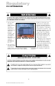
Regulatory FCC INFORMATION 1. Use the power and video cables supplied with this equipment to help prevent interference with radio and television reception. The use of cables and adapters may cause interference with electronic equipment in the vicinity of this unit. ZX STATION 3. Operation of this equipment in a residential area is likely to cause interference in which case the user will be required to correct the interference at his own expense.
Contents STARTING POINT Shipment Contents User Manual Product Description Drawing of Slide Installation Tools Required Precautions 4 4 4 5 6 7 7 INSTALL SLIDES Slide Removal Install The Slides In Rack Frame 8 8 9 INSTALL ZX STATION Install The ZX Station In Rack Frame Installation Test Final Adjustments Securing ZX Station In Rack Frame Installing Cables OPERATION Powering Up Controls And Displays TranzPak 6 TranzPak 6 Front Panel Function Switch Disk Module Handle Front Panel Functioning Installing Dis
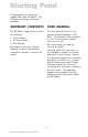
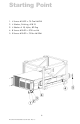
Starting Point Congratulations on selecting a rugged field-ready ZX Station -- the ultimate processing powerhouse available. SHIPMENT CONTENTS USER MANUAL The ZX Station shipping box contains the following: The User Manual comes in two formats: printed hardcopy or CDROM. This Manual is also available on the Z Microsystems website (www.zmicro.com).
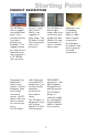
Starting Point PRODUCT DESCRIPTION The ZX Station, with its rugged removable hard drive, is the ultimate processing system powerhouse available. This rugged workstation and server is designed to be rack mounted in a 19 RETMA rack enclosure. At only 7 high (4U), the ZX Station is as rugged as it looks sharp. The ZX Station is built with the powerful Intel or Sun processor.
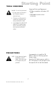
Starting Point 1. 4 Screws #10-32 x .75 Oval Hd Phil 2. 4 Washer, Finishing, #10 SS 3. 4 Washer # 10, Nylon, 82 Deg 4. 8 Screws #10-32 x .375 Low Hd 5. 8 Screws #10-32 x .75 Pan Hd SEM 6 Document# 27-0007UM Issued 11/00 Rev. 1.
Starting Point TOOLS REQUIRED Required Tools and Equipment DANGER: To avoid shock hazard: Phillips screwdriver with about 10" shaft. Do not connect or disconnect the ZX Station during an electrical storm. Adjustable wrench or box wrenches The power cord plug must be connected to a properly wired and grounded power outlet. Any equipment to which the ZX Station will be attached must also be connected to properly wired and grounded power outlets.
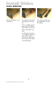
Install Slides SLIDE REMOVAL Lay the ZX Station on a workbench. The slide rail will reach a stop about half way out. This is a safety stop to prevent the ZX Station from sliding out too far while mounted to the rack. Simultaneously press in the safety catches on each slide rail and remove the slide rails all the way off the back of the ZX Station. 8 Document# 27-0007UM Issued 11/00 Rev. 1.0 The slides should now be separated from the ZX Station.
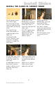
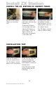
Install Slides INSTALL THE SLIDES IN CABINET FRAME Use the proper screws (from left to right). Pancakehead Phillips screw to install the front of the slider rail and top of lid. Panhead Phillips screw and washer to install the back of the slider rail. Ovalhead Phillips screw, stainless steel and nylon receptacle washers to install the front panel. On the front of the RETMA Rail, use three pancakehead Phillips screws per side to secure the right and left slider rails.
Install ZX Station INSTALL THE ZX STATION IN CABINET FRAME Pull the two ZX Station slides out until they lock. Hold the ZX Station by each side, with the front towards you. Guide the ZX Station into the slide rails and slide the ZX Station in until it stops. If the ZX Station binds, the rollers are not properly in the slide rails. INSTALLATION TEST Slide the ZX Station in and out several times. The ZX Station should easily close completely.
Install ZX Station FINAL ADJUSTMENTS Slide the ZX Station partially out. Lift the ZX Station while tightening the pancakehead Phillips screws in the front slider bracket. Go to the rear of the cabinet to tighten the slider rail screws. If there is not enough room to work at the back of the cabinet, the ZX Station may need to be removed to tighten the rail screws. The ZX Station should slide in and out easily. If not, repeat these adjustment steps. The ZX Station should now slide in and out smoothly.
Install ZX Station INSTALLING CABLES Several cables connect the back of the ZX Station to other equipment, depending upon the ZX Station internal configuration. WARNING: Be sure all electrical power to the cabinet is off before connecting any of the cables. Power cable Video cable WARNING: There is a key guide for alignment on all the cables. Be sure the cable plug and receptacles are aligned properly using the key guide. Misalignment can cause short circuiting.
Operation POWERING UP Switch the ZX Station on by pushing and releasing the power switch located on the right of the center front panel. CONTROLS AND DISPLAYS Peripheral options from left to right, top to bottom: On the right panel of the ZX Station, from left to right, top to bottom: Empty slot front cover. 3-1/2 inch floppy drive. CD-ROM. Power light. Power switch. Press down and release for on. Handle for TranzPak 6 removable memory drive. Power Light. Active Light.
Operation TRANZPAK 6 The rugged TranzPak 6 is a removable mass storage system. TranzPak 6 provides 4.5GB to 36.4GB of archiving power, a wide range of security logistics and flexibility in media selection. These rugged highperformance modules withstand daily insertion and removal. Ultra rugged TranzPak 6 multipurpose storage modules house any 3.5or 5.25 peripheral devices. The high life-cycle connectors are designed to last in excess of 25,000 cycles.
Operation TRANZPAK 6 FRONT PANEL The front panel of the TranzPak 6 contains three LEDs, a SCSI ID indicator, a push-switch to set the SCSI ID and a function switch. The top LED indicates power to the hard disk drive. The middle LED indicates an active state when the computer is accessing the TranzPak 6. The bottom LED indicates a read only state. The SCSI ID Indicator shows a number, which is the setting for the disk module.
Operation TRANZPAK 6 FUNCTION SWITCH The function switch has multiple features and is used for a variety of tasks in operating a disk module and its internal disk drive. DISK MODULE HANDLE The handle serves several functions: (1) it is an on/off power switch for the internal hard disk drive, (2) it is a mechanical lock, and (3) it disengages the module latch to allow removal of the disk module from the docking base. Handle used in disk module insertion. Handle Handle used to carry disk module.
Operation FRONT PANEL FUNCTIONING The following Table describes the functioning of the TranzPak 6 disk modules front panel during various functions. 17 Document# 27-0007UM Issued 11/00 Rev. 1.
Operation INSTALLING DISK MODULE Although the handle does not have to be used for supporting the module during installation, it is designed as an installation aid by holding the entire weight of a loaded disk module in any position. NOTE: The disk module can be installed with the disk module handle in any of its five positions and the function switch in any of its four positions. However, it is recommended that the handle be pulled out and that the function switch be in an unlocked mode.
Operation POWERING UP THE HARD DISK The disk module handle is the on/off power switch for the hard disk drive. When the handle is pushed fully in, power is applied to the hard disk drive inside the disk module. The hard disk will spin and the light green power LED will illuminate, staying illuminated as long as the handle is fully in.
Operation FUNCTION SWITCH ELECTRICAL DESCRIPTION The function switch has four positions: NOTE: Some disk manufacturers require that the power to the disk be cycled after setting it to a write-protect mode in order to use the write-protect feature. The only way to determine if the disk requires power-down to change to Read-Only is to turn the function switch to a RO position, then try to write to the disk. Two Read/Write (RW). The hard disk can be fully accessed by the host computer.
Operation LOCKING THE DISK MODULE AND HARD DISK When the function switch knob is in either the left two disk accessing positions, the disk module handle can be moved freely from being Fully In to power the hard disk, to being Fully Out to remove power from the hard disk drive and to remove the module from the docking base. When the function switch knob is in either of the right two positions, the disk module handle is locked and cannot be moved.
Operation OPERATING THE DISK MODULE Once the hard disk is operational and set to the desired mode, it is ready to be used on the SCSI bus. NOTE: Refer to the operating system User Manual for the operation of the specific hard disk drive. NOTE: Depending on the host operating system, the computer may or may not have to be rebooted after adding a new device. Refer to the operating system User Manual.
Operation CARRYING THE DISK MODULE The handle can be used to carry the disk module. No special precautions are needed. INSTALLING YOUR OWN HARD DISK DRIVE Refer to the TranzPak 6 User Manual for detailed instructions on installing your own hard disk drive into the ZX Station.
Internal Access OPENING THE ZX STATION One of the many design features of the ZX Station is the ease of access to the inside of the processing unit. To open the ZX Station in the rack, perform the following steps: (cables into back of ZX Station) Be sure the power switches on the front and back are off. Disconnect all the cables from the back of the ZX Station to their respective units. Remove the four ovalhead Phillips screws on the corners of the front panel and sliding the ZX Station all the way out.
Maintenance CLEAN FRONT PANEL WARNING: Be sure to turn off the power before performing any maintenance on the ZX Station Gently wipe the front panel of the ZX Station with a soft cloth. Remove finger marks and grease with a damp cloth and mild detergent. DO NOT use solvents or abrasives. Never use flammable cleaning material to clean the front panel of the ZX Station or other electrical apparatus. 25 Document# 27-0007UM Issued 11/00 Rev. 1.
Troubleshooting FRONT PANEL Check that power cable is properly connected to 110 vac power supply. Power light does not illuminate Check that front panel power switch is on Check that power switch on back of ZX Station next to power plug is on. ZX STATION CONFIGURATION Because of the many configurations that the ZX Station can have with various combinations of components, visit the Z Microsystems Website for the latest Troubleshooting guidance. www.zmicro.
Specifications The exact specifications may vary, depending on the combination of components ordered for the ZX Station. Dimensions Weight Power 7.00 H x 17.5 W x 19.0 D 24 lbs. 90 - 132 vac or 180 - 264 VAC (switchable) 250 watts max. 175 watts typical 10° C to 35° C (50 to 95° F) -20° C to +60° C (-4° F to 140° F) 40% to 80% noncondensing 30% to 90% noncondensing TBD TBD UL 1950 FCC Class A Additional extended range environmental military specifications can be met with optional enhancements.
Appendix WARRANTY 1 Year Extended Warranty Extent of Limited Warranty 1. Z Microsystems, Inc. (Z Micro) warrants to the end-user that Z Micro products will be free from defects in materials and workmanship for a specified time after the date of purchase. The duration of this limited warranty is stated above. Certain additional conditions and limitations of Z Micros warranty are stated in the User Guide.
Appendix WARRANTY United States, as well as some governments outside the United States (including provinces in Canada), may: Preclude the disclaimers and limitations in this Warranty Statement from limiting the statutory rights of a consumer (for example, Australia and the United Kingdom); Otherwise restrict the ability of a manufacturer to make such disclaimers or impose such limitations; Grant the customer additional warranty rights, specify the duration of implied warranties which the manufacturer cann
Appendix WARRANTY How long does it take? Your equipment should be returned to you within 30 days of its receipt at the factory. In many cases it will be less (our goal is to have your equipment on its way back within 5 days). However, if the damaged equipment has to be serviced by the original manufacturer (Seagate, NEC, for example), it may take longer. Are there any extra costs? The only per incident cost you will incur is Freight In to return the equipment to the factory.
Appendix Y2K COMPLIANCE Z Microsystems has achieved full Y2K Compliance. In late 1997, the companys senior management assigned a Y2K Project Team that consists of a cross-functional representation from information technology, procurement, manufacturing, test and development, finance, general affairs, engineering, marketing and facilities organizations to address the Year 2000 issues.
Support FURTHER HELP If you are unable to correct any problem yourself, contact: Z Microsystems at: (858) 657-1000 Fax: (858) 657-1001 Website: www.zmicro.com Before calling, please have available as much of the following information as possible: 1. Model and serial number from the label on the monitor. 2. Purchase P.O. 3. Description of problem. NOTE: If possible, stay by the computer. The Z Microsystems Technical Support Representative may wish to go through the problem over the telephone. 4.
Support REPLACING PARTS If the Z Microsystems Technical Support Engineer determines that the product needs to be replaced, a Customer Service Representative will issue a Return Material Authorization (RMA) number and return address. A RMA number is required to return a product to Z Microsystems, regardless of the reason for the return. The following information is required when returning Z Microsystems products: 1. Model number 2. Serial number 3. Date of purchase 4.
Z Microsystems, Inc. 5945 Pacific Center Blvd., Suite 509 San Diego, CA 92121 Phone: (858) 657-1000 Fax; (858) 657-1001 Website: www.zmicro.com Copyright 1999 Z Microsystems, Inc. All Rights Reserved Document# 27-0007UM Issued 11/00 Rev. 1.