
User manual

STAIRCASE TIME DELAY SWITCH ASM-01/U
INSTRUCTION
MANUAL
Zakład Mechaniki i Elektroniki
ZAMEL sp.j.
J.W. Dzida, K. Łodzińska
ul. Zielona 27, 43-200 Pszczyna, Poland
Tel. +48 (32) 210 46 65, Fax +48 (32) 210 80 04
www.zamelcet.com, e-mail: marketing@zamel.pl
VER. 001_01.04.2010
FEATURES
TECHNICAL PARAMETERS
DESCRIPTION
APPEARANCE
ASM-01/U
Input (supply) terminals: A1, A2
Input rated voltage: 12 ÷ 240 V AC/DC
Input voltage tolerance: from -15 to +10%
Nominal frequency: 50 / 60 Hz
Rated power consumption: 8 mA
Supply/release terminals: IN / IN (connected inside the device)
Output relay optical signalization: red LED diode
Time adjustment range: from 10 sec to 10 min
Time accuracy adjustment: ±10 %
Time repeatability adjustment: ±5 %
Time adjustment: smooth (rotary potentiometer)
Output relay parameters: 1NO - 16A/250 V AC1 4000 VA
Number of terminal clamps: 4
Section of connecting cables: from 0,2 to 2,50 mm
2
Ambient temperature range: from -20 to +45
o
C
Operating position: free
Mounting: TH35 rail (PN-EN 60715)
Protection degree: IP20 (PN-EN 60529)
Protective class: II
Overvoltage category: II
Pollution degree: 2
Rated impulse withstand voltage: 1 kV (PN-EN 61000-4-5)
Dimensions (height / width / depth): monomodular(17,5mm) 90x17,5x66mm
Weight: 0,078 kg
Reference standards: PN-EN 60669-1; PN-EN 60669-2-1
PN-EN 61000-4-2,3,4,5,6,11
● Operating time adjustment from 10
seconds to 10 minutes
● universal supply voltage 12÷240V
AC/DC
● cooperation with 3- or 4-wires instal-
lation
● relay output - 1 voltage contact con-
tact max 16 A capacity,
● monomodular casing.
The staircase lighting time delay
switch ASM-01/U is used to control ligh-
ting devices on staircases and corridors.
After releasing the system it switches
on the lighting for the preset time by the
user. After that it switches off automa-
tically. The operating time can be adju-
sted from 10 sec to 10 min by means
of a potentiometer. The staircase ligh-
ting time delay switch ASM-01/U can be
used as standard time delay relay.
The device is designed
for one-phase installation
and must be installed in
accordance with stan-
dards valid in a particular
country. The device sho-
uld be connected accor-
ding to the details included in this opera-
ting manual. Installation, connection and
control should be carried out by a quali-
ed electrician staff, who act in accordan-
ce with the service manual and the device
functions. Disassembling of the device is
equal with a loss of guarantee and can
cause electric shock. Before installation
make sure the connection cables are not
under voltage. The cruciform head screw-
driver 3,5 mm should be used to instal the
device. Improper transport, storage, and
use of the device inuence its wrong func-
tioning. It is not advisable to instal the de-
vice in the following cases: if any device
part is missing or the device is damaged
or deformed. In case of improper functio-
ning of the device contact the producer.
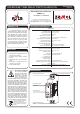
CAUTION
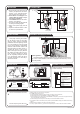
Time adjustment
Output relay optical
Input (supply) terminal (A1) Input (supply) terminal (A2)
signalization
Supply/release terminals
(IN, IN)
The symbol stands for selective
collection of electrical and
electronic devices. Placing used
devices with other waste is not
allowed