
User manual


Warning! Before gas connection
disconnect the mains plug from the
mains socket or switch off the fuse in
the fuse box. Close the primary valve of
the gas supply.
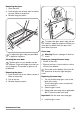
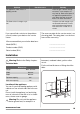
Supply piping should not be less than
R3/8. Connection is made to the Rc ½
(1/2 “ B.S.P.) female threaded. Entry pipe lo-
cated just below the hob level on the rear left
hand side of the appliance.
The gas supply ramp is on the rear side of the
appliance.
Warning! Only liquid sealants to be used
when inlet gas pipe is fitted i.e.: do not
use P.T.F.E. sealant tape.
When installation is complete. Carry out a gas
tightness test and make sure that the seal of
each pipe fitting is correct.
Important! Use flexible tubing, which comply
with BS.669 current edition.
A
B
C
C
D
E
Warning! The gas bayonet must be in
mark area.
Dimension mm
A 250
B 680
C 50
D 250
Dimension mm
E 580
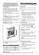
Pressure test
The Rapid injector is used as a pressure test
point.
1. Connect the pressure gauge to the Rapid
injector.
2. Examine the supply pressure by turning the
Rapid burner and one other burner fully on,
and lighting them. The pressure must be:
a) 20 mbar for Natural Gas
b) 29 mbar for LPG, butane only
c) 37 mbar for LPG, propane only.
3. Turn the taps off and disconnect the pres-
sure gauge.
4. Make sure that all burners work correctly.
Checking the grill
1. Put in the grill pan containing the grid.
2. Light the grill burner by turning the grill
control knob to the symbol
.
3. Release the knob when the burner comes
on.
Checking the hob burners
1. Lift the lid.
2. Put in the burner crowns and caps. Make
sure that they are correctly seated.
3. Put in the pan supports.
4. Check each of the burners in turn by turn-
ing the burner control knob to the symbol
.
5. Release the knob when the burners come
on.
Checking the oven burners
1. Push the gas oven control knob and turn it
to
position.
2. Keep it pushed until the oven burners
come on (about 10 seconds).
3. Set the flame.
4. Turn the control knob off and check that
the oven flames go out.
21
www.zanussi.com