
Service manual


210-10 ADL 41/62 599 75 60-77
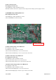
4. Cautions:
(1) Before replacing indoor mainboard, check if the substituted mainboard is qualified. The following tests shall be done:
a. Test if protective tube FUSE1 is open-circuit. If so, replace it with a protective tube of same model.
b. Energize the unit to test if the buzzer will sound. If not, this mainboard of the indoor unit can’t be used.
c. Equip the display and energize the unit to test if the display is normal. If not, that mainboard of indoor unit can’t be used.
(2)The model of the mainboard used for replacement shall be the same as the previous mainboard which has malfunction. And
the model of jumper cap assembled for the new mainboard shall also be the same as that of previous mainboard.
(3) The wiring shall also be the same.
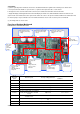
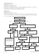
Function of Outdoor Mainboard
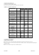
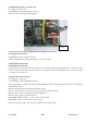
Introduction to each Detection Point
No. of
Detection
point
Detection point
Corresponding parameter
Test value under normal
conditions
Point 1
Between AC-L1,N1
Neutral and live wire
165 V ~ 253 V
Point 2
Left side of R201;U404 heat sink
DC bus bar
230 V ~ 380 V
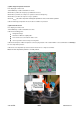
Point 3
Top of D304;bottom of D304
IPM drive voltage+15V
13.5 V ~15.5 V
Point 4
Top of C116; bottom of C116
Relay drive voltage+12V
11 V ~13 V
Point 5
Right side of R228; left side of R228
PFC drive voltage+15V
13.5 V ~15.5 V
Point 6
Two pins on upper left of U4; bottom
of U4 (the top is close to “U4”silk
screen)
Chip+3.3V
3.1 V ~3.3 V
Point 7
Two pins on upper left of U4;
Bottom of U4
+5V
4.8 V ~5.1 V
Point 8
Bottom of R506; bottom of U4
Signal is received by outdoor
unit
Between 0 and 3.3V
Point 9
Bottom of R523; bottom of U4
Signal is sent by outdoor unit
Between 0 and 3.3V
Point 10
Between AC-L2/4V
Neutral and live wire
165 V ~ 253 V
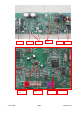
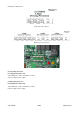
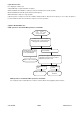
Rectify filtering circuit
Detection point: rectify
voltage
DC motor control circuit
Detection point: output
voltage
4-way valve control circuit
Detection point: output
voltage
Heavy current filter
circuit
Detection point:
voltage after filtering
Communication
circuit
Detection point:
communication
Temperature input
circuit
Detection point:
IC insert voltage
Compressor driver circuit
Detection point:
Up/Un,
Vp/Vn,
Wp/Wn,
voltage waveform,
3-phase current
waveform
Power on-off circuit
Detection point:
chip:5V
PFC AND IPM:15V
Relay:12V
PFC circuit
Detection
point:
generatrix
voltage