ELECTRONIC • OLEODYNAMIC • INDUSTRIAL EQUIPMENTS CONSTRUCTION Via Parma, 59 – 42028 – POVIGLIO (RE) – ITALY Tel +39 0522 960050 (r.a.) – Fax +39 0522 960259 e-mail: zapi@zapispa.it – web: www.zapispa.
Copyright © 1975-2008 Zapi S.p.A. All rights reserved The contents of this publication is a ZAPI S.p.A. property; all related authorizations are covered by Copyright. Any partial or total reproduction is prohibited. Under no circumstances will Zapi S.p.A. be held responsible to third parties for damage caused by the improper use of the present publication and of the device/devices described in it. Zapi spa reserves the right to make changes or improvements to its products at any time and without notice.
Contents 1 2 3 4 5 6 7 8 INTRODUCTION ...................................................................................................................5 SPECIFICATION ...................................................................................................................6 2.1 Technical specifications..............................................................................................6 2.2 Block diagram ..............................................................................
8.5 Parameter regulation ................................................................................................ 47 8.5.1 Traction....................................................................................................... 47 8.5.2 Pump .......................................................................................................... 50 8.6 Programming console functions ............................................................................... 54 8.
1 INTRODUCTION Within the ZAPIMOS family, the ACE-2 inverter (E stands for evolution) is the model suitable for control of 4.0 kW to 9.0 kW motors. It has been expressly designed for battery electric traction. It is fit for electric truck, material handling: order pickers, reach truck, CB 2,0 tons, tractors, boom lift and scissors lift.
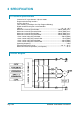
2 SPECIFICATION 2.1 Technical specifications Inverter for AC asynchronous 3-phase motors Regenerative braking functions Can-bus interface Flash memory (128 Kbytes On-Chip Program Memory) Digital control based upon a microcontroller Voltage:.............................................................................................. 24 - 36 - 48 V Maximum current ACE2 24V/400: ............................................. 400 A (RMS) for 3' Maximum current ACE2 36-48V/350: ..................................
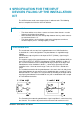
3 SPECIFICATION FOR THE INPUT DEVICES FILLING UP THE INSTALLATION KIT The ACE2 inverter needs some external parts in order to work. The following devices complete the kit for the ACE2 installation. 3.1 Microswitches - The microswitches must have a contact resistance lower than 0.1 Ω and a leakage current lower than 100 µA. When full load connected, the voltage drop between the key switch contacts must be lower than 0.1 V.
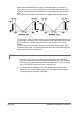
signal level (PROGRAM VACC function), in either direction. This function is unique when it is necessary to compensate for asymmetry with the mechanical elements associated with the potentiometer, especially relating to the minimum level. The sequence of procedure is described in the programming console manual. The two graphs show the output voltage from a non-calibrated potentiometer with respect to the mechanical “zero” of the control lever. MI and MA indicate the point where the direction switches close.
3.4 Speed feedback The motor control is based upon the motor speed feedback. The speed transducer is an incremental encoder, with two phases shifted at 90°. The encoder can be of different types: - power supply: +5 V or +12 V. - electric output: open collector ( NPN), push-pull - standard (A and B) output. For more details about encoder installation see also chapter 4.2.5.
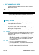
4 INSTALLATION HINTS In the description of these installation suggestions you will find some boxes of different colors, they mean: 4 U These are information useful for anyone is working on the installation, or a deeper examination of the content These are Warning boxes, they describe: - operations that can lead to a failure of the electronic device or can be dangerous or harmful for the operator; - items which are important to guarantee system performance and safety 4.
4.2 Installation of the hardware U Before doing any operation, ensure that the battery is disconnected and when all the installation is completed start the machine with the drive wheels raised from the floor to ensure that any installation error do not compromise safety. After operation, even with the Key Switch open, the internal capacitors may remain charged for some time.
4.2.3 Wirings: CAN connections and possible interferences 4 CAN stands for Controller Area Network. It is a communication protocol for real time control applications. CAN operates at data rate of up to 1 Megabits per second.
The black lines are the power cables. This is apparently a good layout, but can bring to errors in the can line. The best solution depends on the type of nodes (modules) connected in the network. If the modules are very different in terms of power, then the preferable connection is the daisy chain.
account thermal and voltage drop problems. 4 Can advantages: The complexity of today systems needs more and more data, signal and information must flow from a node to another.
Connection of encoder with +12 V power supply. U VERY IMPORTANT It is necessary to specify in the order the type of encoder used, in terms of power supply, electronic output and n° of pulses for revolution, because the logic unit must be set in the correct way by Zapi. 4.2.6 Main contactor and key connection - The connection of the main contactor can be carried out following the drawing in the figure - The connection of the battery line switches must be carried out following ZAPI instructions.
4.3 Protection and safety features 4.3.1 Protection features The ACE-2 is protected against some controller injuries and malfunctions: - Battery polarity inversion It is necessary to fit a MAIN CONTACTOR to protect the inverter against reverse battery polarity and for safety reasons. - Connection Errors All inputs are protected against connection errors. - Thermal protection If the controller temperature exceeds 75 °C, the maximum current is reduced in proportion to the thermal increase.
failure in the "SAFETY" circuit, the microcontroller itself will bring the machine in a safe status. Suggested connection of "SAFETY" circuit: - STANDALONE CONFIGURATION: it is suggested to connect safety input to the "SEAT" microswitch or to the "DEADMAN" microswitch (it depends on the application); in this way the machine will be brought to a safe status as soon as the operator leaves the machine.
simulate external undesired disturbances and verify the electronic devices response. 3) The second type of immunity, ESD, concerns the prevention of the effects of electric current due to excessive electric charge stored in an object. In fact, when a charge is created on a material and it remains there, it becomes an “electrostatic charge”; ESD happens when there is a rapid transfer from a charged object to another.
time the source of ESD. 4.5 Various suggestions - - Never connect SCR low frequency chopper with ASYNCHRONOUS INVERTER because the ASYNCHRONOUS filter capacitors alter the SCR choppers' work. If it is necessary to use two or more control units (traction + lift. for ex.), they must belong to the ZAPIMOS family. During battery charge, disconnect ASYNCHRONOUS from the battery.
5 OPERATIONAL FEATURES - - Page - 20/83 Speed control (three versions available: sensored, sense coil and sensorless as explained in the introduction section) . Optimum behaviour on a slope due to the speed feedback: the motor speed follows the accelerator, starting a regenerative braking if the speed overtakes the speed set-point. the system can perform an electrical stop on a ramp (the machine is electrically hold on a slope) for a programmable time (see also chapter 8.4).
5.1 Diagnosis The microcontroller continually monitors the inverter and carries out a diagnostic procedure on the main functions. The diagnosis is made in 4 points: 1) Diagnosis on key switch closing that checks: watchdog circuit, current sensor, capacitor charging, phase's voltages, contactor drives, can-bus interface, if the switch sequence for operation is correct and if the output of accelerator unit is correct.
6 DESCRIPTION OF THE CONNECTORS 6.1 Connectors of the logic - Traction configuration Page - 22/83 A1 KEY Connected to the power supply through a microswitch (CH) with a 10 A fuse in series. A2 PPOT Potentiometer positive: 12 V / 5 V output; keep load > 1 kohm / 0.5 kohm. A3 CPOT Accelerator potentiometer wiper. A4 FORW Forward direction request input. It must be connected to the forward direction microswitch, active high. A5 REV Backward direction request input.
connected to +Batt) A20 CAN-L Low level CAN-BUS voltage I/O. A21 CAN-H High level CAN-BUS voltage I/O. A22 PTHERM Input for motor temperature sensor. It is possible to use a digital or analogue (PTC) sensor. A23 NTHERM -Batt. B1 PCLRXD Positive serial reception (Not used: it can be disconnected). B2 NCLRXD Negative serial reception. B3 PCLTXD Positive serial transmission. B4 NCLTXD Negative serial transmission. B5 GND Negative console power supply.
connected to -Batt. A14 ENCB Incremental encoder phase B input. A15 ENC GND Encoder negative power supply. A16 NLC Main contactor coil output. The coil is driven to negative reference. A17 PLC/PAUX Positive of the LC and Auxiliary coil. A18 NAUX Auxiliary coil output. The coil is driven to negative reference. A19 SAFETY OUT In the COMBI configuration it is connected to SAFETY IN (CNA#11) of traction controller.
7 DRAWING 7.
7.
7.
7.
8 PROGRAMMING & ADJUSTMENTS USING DIGITAL CONSOLE 8.1 Adjustments via Console Adjustment of Parameters and changes to the inverter’s configuration are made using the Digital Console. The Console is connected to the “B” connector of the inverter. 8.2 Description of Console & Connection Digital consoles used to communicate with AC inverter controllers must be fitted with EPROM CK ULTRA, minimum "Release Number 3.02".
8.3 Description of Standard Console Menu 8.3.
8.3.
8.4 Function configuration 8.4.1 Traction Using the CONFIG MENU of the programming console, the user can configure the following functions (see "OPERATIONAL FEATURE" chapter for an explanation of "hydraulic steering function"): SUBMENU "SET OPTIONS" 1) DISPLAY TYPE This parameter decides wich display is connected to the inverter. 0: No Display 1: MDI PRC connected 2: ECO DISPLAY connected 3: SMART DISPLAY connected 4: MDI CAN connected 2) TILLER SWITCH This option handles the input CNA#6 .
- OFF: the stop on ramp feature is not performed. 7) AUX OUTPUT #1 - HYDRO CONT.: the inverter manages an hydraulic steering function when the direction input or brake pedal input are active or a movement of the truck is detected. - EXCLUSIVE HYDRO: the inverter manages an hydraulic steering function when the exclusive hydro input is active. - BRAKE: output A18 drives an electromagnetic brake coil which is activated every time the traction motor is driven. 8) SET MOT.
7) THROTTLE Y POINT This parameter changes the characteristic of the accelerator input curve. VACC MIN and VACC MAX are values programmable by the "Program Vacc" function. 8) BATT. MIN. ADJ. It adjusts the lower level of the battery discharge table. It is used to calibrate the discharge algorithm with the battery of the application. See chapter 9.5 for more information. 9) BATT. MAX. ADJ. It adjusts the upper level of the battery discharge table.
- NONE: No CHECK UP NEENED warning OPTION#1: CHECK UP NEENED warning shown on the hand set and MDI after 300 hours OPTION#2: Equal to OPTION#1 but Speed reduction after 340 hours OPTION#3: Equal to OPTION#2 but the truck definitively stops after 380 hours 14) MAIN CONT VOLT It specifies the percentage of battery voltage supplied to MC coil to close the contactor. 15) AUX OUT VOLT It specifies the percentage of battery voltage supplied to EB coil to apply the electro mechanic brake. 16) MAIN CONT.
AUX OUTPUT BRAKE BRAKE HYDRO CONT. STOP ON RAMP ON OFF ON HYDRO CONT. OFF EXCL. HYDRO ON EXCL. HYDRO OFF Page - 36/83 A18 OUTPUT -It drives the coil of a electromagnetic brake. -The hydraulic steering function request is sent to the pump inverter by the can-bus link. -It drives the coil of a electromagnetic brake. -The hydraulic steering function request is sent to the pump inverter by the can-bus link.
SUBMENU "SPECIAL ADJUST" 1) ADJUSTMENT#01 Reserved. 2) ADJUSTMENT#02 Reserved. 3) SET CURRENT It adjusts the regolation of maximum current. It shouldn’t be changed. 4) HIGH ADRESS Reserved. 5) DEBUG MODE Reserved. 6) INVERTER TYPE It decides what kind of inverter is used. 0 and 1: traction. 2 and 3: pump. The change of this parameter changes the other parameters at the next keyoff.
4: MDI CAN connected 2) TILLER SWITCH This option handles the input CNA#6 . This input opens when the operator leaves the truck. It is connected to a key voltage when the operator is present. There are two levels: - HANDLE: CNA#6 is managed as tiller input (no delay when released). - SEAT: CNA#6 is managed as seat input (with a delay when released debouncing function) 3) HOUR COUNTER - RUNNING: the counter registers travel time only. - KEY ON: the counter registers when the "key" switch is closed.
SUBMENU "ADJUSTMENTS" 1) SET BATTERY TYPE It selects the nominal battery voltage. 2) ADJUST BATTERY Fine adjustment of the battery voltage measured by the controller. 3) THROTTLE 0 ZONE It establishes a dead band in the lift potentiometer input curve (see also curve below).
7) BATT. MAX. ADJ. It adjusts the upper level of the battery discharge table. It is used to calibrate the discharge algorithm with the battery of the application. See chapter 9.5 for more information. 8) ADJUSTMENT #03 This parameter adjusts the updating of battery charge after Key-On. Decreasing this parameter the minimum difference between the battery voltage measured after Key-On and the last stored value, necessary to update the charge with the new value measured, decrease.
and then the voltage will be reduced to 49% of battery voltage. 15) AUX OUTPUT V RID It specifies the percentage of AUX OUT VOLT parameter, supplied to EB coil to keep the electro mechanic brake applied. Example 1 MAIN CONT VOLTAGE = 100% MAIN CONT V RID = 70% The load will be closed with full battery voltage applied to the coil and then the voltage will be reduced to 70% of battery voltage.
SUBMENU "SPECIAL ADJUST" 1) ADJUSTMENT#01 Reserved. 2) ADJUSTMENT#02 Reserved. 3) SET CURRENT It adjust the regolation of maximum current. It shouldn’t be changed. 4) HIGH ADRESS Reserved. 5) DEBUG MODE Reserved. 6) INVERTER TYPE It decides what kind of inverter is used. 0 and 1: traction. 2 and 3: pump. The change of this parameter changes the other parameters at the next keyoff.
Flow chart showing how to make changes to OPTION Menu. 1) Opening Zapi Menu. AE2T2B ZP0.12 24V 400A 00000 2) Press Top Left & Right Buttons to enter SET Menu. 3) The Display will show: SET MODEL. % ' % ' ' ' CONFIG MENU SET MODEL 4) Press ROLL UP or ROLL DOWN button until SET MODEL Menu appears. 5) SET OPTIONS appears on the display. % ' ' ' ' ' CONFIG MENU SET OPTIONS ' % ' ' ' ' 6) Press ENTER to go into the SET MODEL Menu. 7) The display will shows the first OPTION.
Flow chart showing how to make changes to ADJUSTMENTS Menu. AE2T2B ZP0.12 24V 400A 00000 1) Opening Zapi Menu. 2) Press Top Left & Right Buttons to enter CONFIG Menu. % ' % ' ' ' CONFIG MENU SET MODEL 3) The display will show: SET MODEL. 4) Press ROLL UP or ROLL DOWN button until ADJUSTMENTS Menu appears. % ' ' ' ' ' CONFIG MENU ADJUSTMENTS 5) ADJUSTMENTS appears on the display. 6) Press ENTER to go into the ADJUSTMENTS Menu. ' % ' ' ' ' 7) The display will shows SET BATTERY TYPE.
Flow chart showing how to use the SET BATTERY TYPE adjustment. 1) Opening Zapi Menu. AE2T2B ZP0.12 24V 400A 00000 2) Press Top Left & Right Buttons to enter CONFIG Menu. 3) The Display will show: SET MODEL. % ' % ' ' ' CONFIG MENU SET MODEL 4) Press ROLL UP button until ADJUSTMENTS Menu appears. 5) ADJUSTMENTS appears on the display. % ' ' ' ' ' CONFIG MENU ADJUSTMENTS 6) Press ENTER to go into the ADJUSTMENTS Menu. ' % ' ' ' ' 7) The display will show: SET BATTERY TYPE.
Flow chart showing how to carry out ADJUSTMENT BATTERY operation by console. AE2T2B ZP0.12 24V 400A 00000 1) Opening Zapi Menu. 2) Press Top Left & Right Buttons to enter CONFIG Menu. % ' % ' ' ' CONFIG MENU SET MODEL 3) The Display will show: SET MODEL. 4) Press ROLL UP button until ADJUSTMENTS Menu appears. % ' ' ' ' ' CONFIG MENU ADJUSTMENTS 5) ADJUSTMENTS appears on the display. 6) Press ENTER to go into the ADJUSTMENTS Menu.
8.5 Parameter regulation In addition to the input configuration, parameter modification is made directly by ZAPI on customer specifications, or by the customer, making the adjustments using the programming console. 8.5.1 Traction The following parameters can be modified: 1) ACCELERATION 0 It specifies the motor acceleration at 0 Hz. At level 0 the acceleration is maximum. Increasing the parameter’s level the acceleration decreases. 2) INV.
9) RELEASE BRAKING Seconds. It controls the deceleration ramp when the travel request is released. The parameter sets the time needed to decelerate the traction motor from 100Hz to 0Hz. 10) INVERSION BRAKING Seconds. It controls the deceleration ramp when the direction switch is inverted during travel. The parameter sets the time needed to decelerate the traction motor from 100Hz to 0Hz. 11) DECELERATION BRAKING Seconds.
Speed reduction when the cutback input is active. 18) FREQUENCY CREEP Minimum speed when the forward or reverse switch is closed, but the accelerator is on a minimum position. 19) MAXIMUM CURRENT This parameter changes the maximum current of the inverter. 20) BRK SMOOTH It gives a parabolic form to the deceleration ramp. 21) STOP BRK SMOOTH Hz. It sets the level of frequency where the smooth effect of the deceleration parabolic form ends. 22) AUXILIARY TIME Time units value (seconds).
4 4 (*) The acceleration time shown is the time from 0 Hz to 100 Hz. This is the ideal ramp calculated by the software; the real ramp could change as a function of motor control parameter setting and, obviously, as a function of the load. (**) The braking feature is based upon deceleration ramps. The value shown in the table is the time to decrease the speed from 100 Hz to 0 Hz.
8) RELEASE BRAKING Seconds. It controls the deceleration ramp when the pump request is released. The parameter sets the time needed to decelerate the traction motor from 100Hz to 0Hz. 9) MAX SPEED LIFT It determines the pump maximum speed when LIFT ENABLE switch is closed . 10) 1ST SPEED COARSE It determines the pump maximum speed when SPEED1 switch is closed . 11) 2ND SPEED COARSE It determines the pump maximum speed when SPEED2 switch is closed .
The following table shows the minimum / maximum programmable value for each parameter. In the table is also present the parameters resolution. PARAMETER UNIT MIN VALUE MAX VALUE RESOLUTION ACCELERATION 0 (*) Sec. 0,3 10 0,1 ACCELERATION 1 (*) Sec. 0,3 10 0,1 ACCELERATION 2 (*) Sec. 0,3 10 0,1 ACCELERATION 3 (*) Sec. 0,3 10 0,1 ACC PROF. FREQ 1 Hz 0 200 1 ACC PROF. FREQ 2 Hz 0 200 1 ACC PROF. FREQ 3 Hz 0 200 1 RELEASE BRAKING (**) Sec.
Flow Chart showing how to make Programme changes using Digital Console fitted with Eprom CK ULTRA. 1) Opening Zapi Display. AE2T2B ZP0.12 24V 400A 00000 ' % ' ' ' ' 2) Press ENTER to go into the General Menu. 3) The Display will show: MAIN MENU PARAMETER CHANGE 4) Press ENTER to go into the Parameter Change facility. 5) The Display will show the first parameter. ' % ' ' ' ' ACCELERATION 0 2 6) Press either ROLL UP and ROLL DOWN to display the next parameter.
8.6 Programming console functions - Functional configuration (see 8.1, 8.2, 8.3, 8.4). Parameter programming (see 8.5.1, 8.5.2). Tester: the user can verify the state of the following parameters: TRACTION battery voltage (V) motor voltage (%) voltage booster (%) frequency (Hz) encoder (Hz) slip value (Hz) current rms (A) motor power (W) battery charge (%) temperature (°C) motor temperat.
8.7 Sequence for Ac Inverter Traction setting When the "Key Switch" is closed, if no alarms or errors are present, the Console Display will be showing the Standard Zapi Opening Display. If the controller is not configured to your requirements, follow the sequence detailed on Chapter 9.2. Remember to re-cycle the Key Switch if you make any changes to the controller’s configuration. Otherwise follow the sequence detailed below: 1) Select the Options required. See Chapter 8.4.1.
8.8 Sequence for Ac Inverter Pump setting When the "Key Switch" is closed, if no alarms or errors are present, the Console Display will be showing the Standard Zapi Opening Display. If the controller is not configured to your requirements, follow the sequence detailed on Chapter 9.2. Remember to re-cycle the Key Switch if you make any changes to the controller’s configuration. Otherwise follow the sequence detailed below: 1) Select the Options required. See Chapter 8.4.2.
8.9 Tester: description of the function The most important input or output signals can be measured in real time using the TESTER function of the console. The Console acts as a multimeter able to read voltage, current and temperature. The following definition listing shows the relative measurements. 8.9.1 Traction 1) BATTERY VOLTAGE Level of battery voltage measured at the input to the key switch.
The level of the Speed Reduction Microswitch. - ON / GND = active entry of speed reduction microswitch. - OFF / +VB = non active entry of microswitch. 17) HAND BRAKE The level of the Hand Brake Microswitch. - ON / GND = active entry of Brake pedal Microswitch. - OFF / +VB = non active entry of microswitch. 18) BRAKEPEDAL POT. The percentage of the pressure on the brake pedal (100% if the pedal is totally pressed, 0% if the pedal is released).
16) 17) 18) 19) 20) - ON / +VB = active entry of closed switch. - OFF / GND = non active entry of open switch. 2ND SPEED SWITCH Status of the second speed switch of the pump. - ON / +VB = active entry of closed switch. - OFF / GND = non active entry of open switch. 3RD SPEED SWITCH Status of the third speed switch of the pump. - ON / GND = active entry of closed switch. - OFF / +VB = non active entry of open switch. HYDRO SPEED REQ. Status of the hydro speed request of the pump.
Flow Chart showing how to use the TESTER function of the Digital Console. AE2T2B ZP0.12 24V 400A 00000 1) Opening Zapi Display. 2) Press ENTER to go into the General menu. ' % ' ' ' ' MAIN MENU PARAMETER CHANGE 3) The Display will show: 4) Press ROLL UP or ROLL DOWN button until TESTER MENU appear on the display. % ' ' % ' ' MAIN MENU TESTER 5) The Display shows: 6) Press ENTER to go into the TESTER function. ' % ' ' ' ' 7) The first variable to be tested is shown on the Display.
8.10 Description of the Console “SAVE” function The SAVE function allows the operator to transmit the Parameter values and Configuration data of the inverter into the Console memory. It is possible to load 64 different programmes. The information saved in the Console memory can then be reloaded into another inverter using the RESTORE function. The data that is available via the SAVE function is as follows: - All Parameter Values (PARAMETER CHANGE). - Options (SET. OPTIONS).
8.11 Description of Console “RESTORE” function The RESTORE PARAM function allows transfer of the Console’s stored data into the memory of the inverter. This is achieved in a fast and easy way using the method previously used with the SAVE PARAM. function. The data that is available via the RESTORE PARAM. function is as follows: - All Parameter Values (PARAMETER CHANGE). - Options (SET OPTIONS). - The level of the Battery (ADJUST BATTERY).
12) You can see the items that are being stored in the inverter memory whilst the RESTORE routine is happening. STORING ACCELER. DELAY 13) When finished the Console displays: MAIN MENU RESTORE PARAM. 14) Press OUT to return to the Opening Zapi Display. ' ' ' ' % ' 8.12 Description of Console “PROGRAM VACC” function This enables adjustment of the minimum and maximum useful signal level, in either direction.
Flow Chart showing how to use the PROGRAM VACC function of the Digital Console. AC2 ZAPI V0.0 48V 350A 00000 1) Opening Zapi Display. ' % ' ' ' ' 2) Press ENTER to go into the General Menu. MAIN MENU PARAMETER CHANGE 3) The Display will show: 4) Press ROLL UP or ROLL DOWN button until PROGRAM VACC appears on the display. % ' ' % ' ' MAIN MENU PROGRAM VACC 5) The Display will show: 6) Press ENTER to go into the PROGRAM VACC routine.
8.13 Description of the battery charge detection setting The Battery Charge detection uses two setting that specify the Full Charge Voltage Level (100%) and the Discharge Voltage Level (10%). These two settings are the Bat.Max.Adj and the Bat.Min.Adj. It is possible to adapt the Battery Charge Detection to your specific battery, by changing the above two settings (e.g. if the Battery Discharged Detection occurs when the battery is not totally discharged, it is necessary to reduce the Bat.Min.
8.14 Description of “ALARMS” menu The ALARMS logbook in the MAIN MENU’ records the alarms of the controller. It has a FIFO (First Input First Output) structure that means the oldest alarm is lost when the database is full and a new alarm occurs.
Flow Chart showing how to use the ALARMS function via the Digital Console. 1) Opening Zapi Display. AE2T2B ZP0.12 24V 400A 00000 ' % ' ' ' ' 2) Press ENTER to go into the General menu. 3) The Display will show: MAIN MENU PARAMETER CHANGE 4) Press ROLL UP or ROLL DOWN button until PARAMETER CHANGE appears on the display. 5) The Display will show: % ' ' % ' ' MAIN MENU ALARMS ' % ' ' ' ' 6) Press ENTER to go into the ALARMS function. 7) The Display will show the most recent Alarm.
WARNINGS: these are faults which do not stop the truck or stop it by a controlled regenerative braking. In other words, the controller is working well, but it has detected conditions to reduce the performances or to stop the truck without opening the power devices. These warnings are related to: - wrong operator sequences - conditions which require performance reduction (like high temperatures, ….) 8.
Safety out The Safety-out driver is damaged (shorted or open) MC is not closed, EB is applied, Traction/Pump stopped Start-up Traction/Pump request Watchdog#1 MDI code allarm 8 The watchdog signal #1 is not in the correct status MC is opened, EB is applied, Traction/Pump stopped Start-up, stand-by, running Key re-cycle Watchdog#2 MDI code allarm 8 The watchdog signal #2 is not in the correct status Start-up, stand-by, running Key re-cycle Keyoff shorted MDI code allarm 76 At Start-up the Keyo
Hardware fault 20 The Mosfets driver are not switched off with Watch-dog signal in alarm status MC is not closed , EB is applied, Traction/Pump stopped Start-up Key re-cycle Hardware fault 21 The EB/AUX driver is not switched off with Watch-dog signal in alarm status MC is not closed , EB is applied, Traction/Pump stopped Start-up Key re-cycle Hardware fault A1 The MC driver is not switched off with Watch-dog signal in alarm status MC is not closed , EB is applied, Traction/Pump stopped Start-u
8.17 Analysis and troubleshooting of alarms displayed on console 1) FLASH CHECKSUM Cause: After Key-on the software verifies the integrity of program stored in the flash memory, if the verify has a negative result this alarm is generated. Troubleshooting: The problem is in the microcontroller flash memory, which could be damaged, or in the program stored inside, which could be corrupted. Try to program the logic again, if the alarms is still signalled the problem is in the microcontroller.
Cause: When the key is switched ON, the inverter tries to charge the power capacitors through a series of a PTC and a power resistance, and check if the capacitor are charged within a timeout. If the capacitor voltage measured is less than 20% of the nominal battery voltage, an alarm is signalled; the main contactor is not closed.
Troubleshooting: - Check if there is a short or a low impedance pull-down between SAFETY OUT (CAN#19) and –BATT. - The driver circuit is damaged in the logic board, which has to be replaced. 10) WATCHDOG#1 Cause: At start-up the watch dog signal is already active before the software has generated it. At stby or running condition the watch dog signal is not active (in alarm status). Troubleshooting: The WD hardware circuit or microcontroller output port are damaged.
- - - If no voltage transient is detected on the supply line and the alarm is present every time the key is switched ON, the failure is probably in the controller hardware, so it is necessary to replace the logic board. Troubleshooting of fault displayed during motor driving; in this case it can be an under voltage or an over voltage condition.
phases voltage to increase toward the rail capacitor value. If the phases voltage is less than 66% of the rail capacitor voltage, this alarm occurs. Cause 2: Motor running test. When the motor is running, power bridge is ON, the motor voltage feedback is tested; if it is lower than commanded value (a window of values are considered) fault status is entered.
Troubleshooting: The problem is inside the controller, no external component are involved, replace the logic board. 22) HARDWARE FAULT 21 Cause: Before driving the MC coil, the controller checks if the EB/AUX driver is turned of by a not active (alarm status) Watch-dog signal. If it is not turned of then the alarm is generated. Troubleshooting: The problem is inside the controller, no external component are involved, replace the logic board.
27) LOGIC FAILURE #2 Cause: Fault is in the hardware section of the logic board which manages the phase’s voltage feedback. Troubleshooting: This type of fault is not related to external components, so when it happens it is necessary to replace the ACE2 logic board. 28) CONTACTOR DRIVER Cause: The MC coil driver is not able to drive the load. The device itself or its driving circuit is damaged. Troubleshooting: This type of fault is not related to external components; replace the ACE2 logic board.
8.18 Microcontroller warning overview Error code Description Effect Machine status when the test is done Restart procedure Vacc not OK The accelerator/ lift potentiometer value is higher than the minimum value recorded, and the direction/enable switches are opened.
8.19 Analysis and troubleshooting of warnings displayed on console 1) VACC NOT OK Cause: The test is made at key-on and immediately after that both the travel demands have been turned off. This alarm occurs if the ACCELERATOR reading in the TESTER menu’ is 1,0V higher than PROGRAM VACC min acquisition when the accelerator is released. Troubleshooting: Acquire the maximum and minimum potentiometer value through the PROGRAM VACC function.
5) MOTOR TEMPERATURE Cause: This warning occurs when the temperature sensor is opened (if digital) or has overtaken the threshold of 150° (if analogue). Troubleshooting: Check the thermal sensor inside the motor (use the MOTOR TEMPERATURE reading in the TESTER menu); check the sensor ohmic value and the sensor wiring. If the sensor is OK, improve the cooling of the motor. If the warning is present when the motor is cool, then the problem is inside the controller.
11) SLIP PROFILE Cause: There is an error on the choice of the parameters of the slip profile. Troubleshooting: Check in the hardware setting menu the value of those parameter 12) EEPROM KO Cause: It’s due to a HW or SW defect of the non-volatile embedded memory supporting the controller parameters. This alarm does not inhibit the machine operations, but the truck will work with the default values. Troubleshooting: Try to execute a CLEAR EEPROM operation (refer to Console manual).
9 RECOMMENDED SPARE PARTS FOR INVERTER Part number Description ACE Version C16588 Protected 350 A strip UL Fuse. 24V/400 & 36-48V/450 C16588 Protected 350 A strip UL Fuse. 24V/500 C16586 Protected 250 A strip UL Fuse.
10 PERIODIC MAINTENANCE TO BE REPEATED AT TIMES INDICATED Check the wear and condition of the Contactors’ moving and fixed contacts. Electrical Contacts should be checked every 3 months. Check the Foot pedal or Tiller microswitch. Using a suitable test meter, confirm that there is no electrical resistance between the contacts by measuring the volt drop between the terminals. Switches should operate with a firm click sound. Microswitches should be checked every 3 months.