ELECTRONIC • OLEODYNAMIC • INDUSTRIAL EQUIPMENTS CONSTRUCTION Via Parma, 59 – 42028 – POVIGLIO (RE) – ITALY Tel +39 0522 960050 (r.a.) – Fax +39 0522 960259 e-mail: zapi@zapispa.it – web: www.zapispa.
Copyright © 1975-2006 Zapi S.p.A. All rights reserved The contents of this publication is a ZAPI S.p.A. property; all related authorizations are covered by Copyright. Any partial or total reproduction is prohibited. Under no circumstances will Zapi S.p.A. be held responsible to third parties for damage caused by the improper use of the present publication and of the device/devices described in it. Zapi spa reserves the right to make changes or improvements to its products at any time and without notice.
Contents 1 2 3 4 5 6 7 8 9 INTRODUCTION ...................................................................................................................6 SPECIFICATION ...................................................................................................................7 2.1 Technical specifications..............................................................................................7 2.2 Block diagrams ...........................................................................
9.2 9.3 10 11 12 13 Description of console (hand set) & connection ....................................................... 35 Description of the console menu .............................................................................. 36 9.3.1 Master: AmpSaab version .......................................................................... 36 9.3.2 Master: AmpSeal version ........................................................................... 37 9.3.3 Slave: AmpSaab version ......................
APPROVAL SIGNS COMPANY FUNCTION INIZIALS GRAPHIC AND LAYOUT FF PROJECT MANAGER FG TECHNICAL ELECTRONIC MANAGER VISA PP SALES MANAGER VISA PN SIGN Publication N°: AEQZP0BA Edition: August 2005 AEQZP0BA – COMBI AC1 - User Manual Page - 5/86
1 INTRODUCTION The COMBI AC1 inverter has been developed to perform all the electric functions that are usually presents in walkie trucks, stackers, low order pickers etc. The controller can perform the following functions: - Page - 6/86 Controller for Ac 700W to 3.5Kw AC motors; Pump controller for series wounded DC motors up to 7,5 Kw.
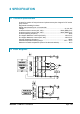
2 SPECIFICATION 2.1 Technical specifications Inverter for traction AC asynchronous 3-phase motors plus chopper for DC series pump motors. Regenerative braking functions. Digital control based upon microcontroller Voltage: ................................................................................................. 24, 36, 48V Inverter maximum current (24V, 36V): ........................................ 350A (RMS) for 2' Inverter maximum current (36V, 48V): ........................................
3 SPECIFICATION FOR THE INPUT DEVICES FILLING UP THE INSTALLATION KIT 3.1 Digital inputs Combi Ac1 digital inputs work in the voltage range [-B; +B]. Related command devices (microswitches) must be connected to +B (typically to key voltage). Pull-down resistance to –B is built-in. Functional devices (like FW, BACK, LIFT, DESCENT, HORN, H&S, TILLER, BELLY switches) are Normally Open; so related function becomes active when the microswitch closes.
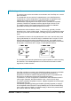
3.2 Analog unit The analog input can be connected to an accelerator unit if the Zapi can or serial tiller is not used. The accelerator unit can consist of a potentiometer or an Hall effect device. It should be in a 3-wire configuration. The potentiometer is supplied through CNA#26 [AmpSaab connector] OR CNA#25 [Ampseal connector]. Potentiometer output signal must be input to CPOT (CNA#24 for AmpSaab connector, CNA#15 for Ampseal connector) signal range is from 0 to 10V.
Also in AmpSeal version a third analog input is available in CNA#17 (a digital input is lost). These other two analog inputs are checked by both microcontrollers too. 3.4 Analog motor thermal sensor input Input CNA#12 in the AmpSaab version [CNA#22 in AmpSeal connector] is an analog input to receive an analog thermal sensor signal to measure the Traction Motor Winding Temperature. The analog device installed in the motor has to be specified, in order to insert the correct look-up table in the software.
4 INSTALLATION HINTS In the description of these installation suggestions you will find some boxes of different colours, they mean: 4 U These are informations useful for anyone is working on the installation, or a deeper examination of the content These are Warning boxes, they describe: - operations that can lead to a failure of the electronic device or can be dangerous or harmful for the operator; - items which are important to guarantee system performance and safety 4.
4.1.3 Fuses - Use a 6.3-10A Fuse for protection of the auxiliary circuits. For protection of the power unit, use a 400A fuse in the Battery Positive connection. For special applications or requirements these values can be reduced. For Safety reasons, we recommend the use of protected fuses in order to prevent the spread of fused particles should the fuse blow. 4.
4.2.2 Wirings: power cables - U The power cables length must be as short as possible to minimize power losses. They must be tightened on controller power posts with a Torque of 13-15 Nm The COMBI AC-1 module should only be connected to a traction battery. Do not use converters outputs or power supplies. For special applications please contact the nearest Zapi Service Centre. Do not connect the controller to a battery with a nominal voltage different than the value indicated on the controller label.
U Wrong Layout: Module 1 Module 2 Module 3 The red lines are can wires. The black boxes are different modules, for example traction controller, pump controller and display connected by canbus. The black lines are the power cables. This is apparently a good layout, but can bring to errors in the can line. The best solution depends on the type of nodes (modules) connected in the network. If the modules are very different in terms of power, then the preferable connection is the daisy chain.
Otherwise, if two controllers are similar in power (for example a traction and a pump motor controller) and a third module works with less current, the best way to deal this configuration is to create a common ground point (star configuration) U Correct Layout: Module 1 Module 2 Module 3 Note: Module 1 power ≈ Module 2 power > Module 3 power In this case the power cables starting from the two similar controllers must be as short as possible.
4.2.5 Connection of the encoder 1) COMBI AC1 card is fit for different types of encoder. To control AC motor with Zapi inverter, it is necessary to install an incremental encoder with 2 phases shifted of 90°. The encoder power supply can be +5 or +12V. It can have different electronic output. AMPSAAB VERSION A9 +5V/+12V A10 GND A8 A A22 B positive of encoder power supply. negative of encoder power supply. phase A of encoder. phase B of encoder.
AMPSEAL VERSION U VERY IMPORTANT It is necessary to specify in the order the type of encoder used, in terms of power supply, electronic output and n° of pulses for revolution, because the logic unit must be set in the correct way by Zapi. The n° of pulses revolution the controller can handle is given by the second-last letter in the software release name (see 3.5). 4.2.6 Main contactor and key connection - The connection of the main contactor can be carried out following the drawing in the figure.
voltage or if the key is switched off before the battery power line is disconnected. AMPSAAB VERSION AMPSEAL VERSION 4.2.7 Insulation of truck frame U Page - 18/86 As stated by EN-1175 “Safety of machinery – Industrial truck”, chapter 5.7, “there shall be no electrical connection to the truck frame”. So the truck frame has to be isolated from any electrical potential of the truck power line.
4.3 Protection and safety features 4.3.1 Protection features The COMBI AC1 is protected against some controller injuries and malfunctions: - Battery polarity inversion It is necessary to fit a LINE CONTACTOR to protect the controller against reverse battery polarity and for safety reasons. - Connection Errors All inputs are protected against connection errors. - Thermal protection If the controller temperature exceeds 85°C, the maximum current is reduced in proportion to the thermal increase.
4.3.2 Safety Features U ZAPI controllers are designed according to the prEN954-1 specifications for safety related parts of control system and to UNI EN1175-1 norm. The safety of the machine is strongly related to installation; length, layout and screening of electrical connections have to be carefully designed. ZAPI is always available to cooperate with the customer in order to evaluate installation and connection solutions.
switching of the mosfets which are working at high frequency and generate RF energy, but wires and cables have the key role to propagate the disturbs because they works as antennas, so a good layout of the cables and their shielding can solve the majority of the emission problems. 2) The study of the immunity can be divided in two main branches: protection from electromagnetic fields and from electrostatic discharge.
3) ELECTROSTATIC IMMUNITY. Three ways can be followed to prevent damages from ESD: A) PREVENTION: when handling ESD-sensitive electronic parts, ensure the operator is grounded; test grounding devices on a daily basis for correct functioning; this precaution is particularly important during controller handling in the storing and installation phase. B) ISOLATION: use anti-static containers when transferring ESD-sensitive material.
5 OPERATIONAL FEATURES - Speed control. - Optimum behaviour on a slope if the speed feedback is used: - The motor speed follows the accelerator, starting a regenerative braking if the speed overtakes the speed set-point - The system can perform an electrical stop on a ramp (the machine is electrically hold on a slope) for a programmable time (if encoder is used) - Stable speed in every position of the accelerator. - Regenerative release braking based upon deceleration ramps.
6 DESCRIPTION OF THE CONNECTORS 6.
AmpSeal Version 1 12 13 23 24 35 6.1.1 CNA connector: AmpSaab Version The connector used is a AMPSAAB plug 42 pins A1 NCLTXD Negative serial transmission pin. A2 PCLTXD Positive serial transmission pin. A3 NEVP Negative of the proportional electrovalve. A4 PAUX Positive supply for electrovalves. This input has to be supplied with positive taken after main contactor and should be used to supply all electrovalves. A5 DESCENT Lowering request input active high.
A18 FW Forward switch input, active high (+VB). A19 BACK Reverse switch input, active high (+VB). A20 IN5 Input of the switch DIGITAL INPUT # 5. A21 HORN Horn switch input, active high (+VB). A22 ENC B Traction motor encoder phase B. A23 NPOT Negative of the accelerator potentiometer, tested for wire disconnection diagnosis. A24 CPOTTR Accelerator potentiometer wiper. A25 CPOTL Lift potentiometer wiper.
A8 NEV5/HORN OUTOut of the electrovalves/Horn driver (driving to –Batt). A9 NEV1 Output of the electrovalve 1 driver (driving to –Batt) A10 +KEY Input of the key switch signal. A11 NEV2 Output of the electrovalve 2 driver (driving to –Batt) A12 NMC Output of the Line Contactor coil driver (driving to – Batt) A13 ENC B Traction motor encoder phase B. A14 ENC A Traction motor encoder phase A. A15 CPOTTR Accelerator potentiometer wiper. A16 NCLTXD Negative serial transmission pin.
6.2 Description of power connections View of the power bars: U +BF +B -B V -P Page - 28/86 W -B Negative of the battery. +B Positive of the battery. +BF Positive of the battery, before the fuse. -P Output of the Pump Motor. U; V; W Connection bars of the three motor phases; follow this sequence and the indication on the motor.
7 DRAWINGS 7.
7.2 Connection drawing 7.2.
7.2.
8 ONE SHOT INSTALLATION PROCEDURE This section of the manual describes the basic connection procedure. To move, the truck needs a minimum I/O outfit that it is mandatory: this minimum outfit is listed in the Steps from 1 to 8 below. Step1 Connect a potentiometer in the range 0.5 to 10Kohms, to modify the wished speed, between CNA#23, CNA#24, CNA#26 [AmpSaab connector] Step2 Connect two travel demand switches.
You must fill your I/O outfit with your optional functions. The optional functions are shown in the connecting drawing and described in detail inside this manual. The index may help you. 8.1 Sequence for Ac Inverter traction setting This section of the manual describes the basic COMBI AC1 set-up procedure using the hand-set: When the "Key Switch" is closed, if no alarms or errors are present, the Console Display will be showing the Standard Zapi Opening Display (Home Display).
Step15 Page - 34/86 Make the choice for the truck behaviour on a slope. If the "Stop on ramp" option is ON, set the desired value of "auxiliary time" parameter.
9 PROGRAMMING & ADJUSTMENTS USING DIGITAL CONSOLE 9.1 Adjustments via console Adjustment of Parameters and changes to the inverter’s configuration are made using the Digital Console. The Console is connected to the CNA connector of the inverter. 9.2 Description of console (hand set) & connection Digital consoles used to communicate with AC inverter controllers must be fitted with EPROM CK ULTRA, minimum Release Number: 3.02. The section describes the Zapi hand set functions.
9.3 Description of the console menu 9.3.
9.3.
9.3.
9.3.
9.4 Function configuration (MASTER) 9.4.1 Config menu “SET OPTIONS” functions list To enter the CONFIG MENU’ it is necessary to push in the same time the right side top and left side top buttons. Then roll until the SET OPTION item appears on the hand set display. Push the ENTER button. CA1S2B ZAPI 1.
connected to a key voltage when the operator is present. There are two levels: - HANDLE: CNA#7 [CNA#1 in AmpSeal] is managed as tiller input (no delay when released). - SEAT: CNA#7 [CNA#1 in AmpSeal] is managed as seat input (with a delay when released Æ debouncing function). 2) HOUR COUNTER This option specifies the hour counter mode.
- NONE: The quick inversion function is not managed (no effect when CNA#33 switches over). TIMED: The quick inversion function is timed. BELLY: The quick inversion function is managed but not timed.
TROTTLE 0 ZONE 7% 11) Press OUT ' ' ' ' % ' 12) Press ENTER to confirm ' % ' ' ' ' 13) Repeat the same from 5 to 12 points for the other adjustments 1) SET BATTERY TYPE Selects the nominal battery voltage. 2) ADJUST BATTERY Fine adjustment of the battery voltage measured by the controller. 3) THROTTLE 0 ZONE Establishes a deadband in the accelerator input curve.
- NONE: No CHECK UP NEENED warning OPTION#1: CHECK UP NEENED warning shown on the hand set and MDI after 300 hours OPTION#2: Equal to OPTION#1 but Speed reduction after 340 hours OPTION#3: Equal to OPTION#2 but the truck definitively stops after 380 hours 11) MAIN CONT. VOLTAGE Percentage of the total voltage of the battery applied to the main contactor coil. 12) AUX OUTPUT VOLTAGE Percentage of the total voltage of the battery applied to the Eb coil. 9.4.
13) The Display will show MAIN MENU PARAMETER CHANGE 1) ACCELER. DELAY Seconds. It determines the acceleration ramp. The parameter sets the time needed to speed up the traction motor from 0Hz to 100Hz. 2) RELEASE BRAKING Seconds. It controls the deceleration ramp when the travel request is released. The parameter sets the time needed to decelerate the traction motor from 100Hz to 0Hz. 3) TILLER BRAKING Seconds. It controls the deceleration ramp when the tiller is in braking position (released).
12) HS CUTBACK Typically from 10% to 100%. It determines the percentage of the max speed applied when the Hard & Soft function (H&S switch on CNA#6 in AmpSaab connector, CNA#29 in AmpSeal connector) is active. When set to 100% the speed reduction is ineffective. 13) CUTBACK SPEED 3 Typically from 10% to 100%. It determines the percentage of the max speed applied when the cutback switch 3 is active. When set to 100% the speed reduction is ineffective. 14) FREQUENCY CREEP Hz value.
PARAMETER PROGRAMMED LEVEL UNIT 0 1 2 3 4 5 6 7 ACCELERATION DELAY Sec. From 0 to 10 sec., resolution of 0.1 RELEASE BRAKING Sec. From 0 to 10 sec., resolution of 0.1 TILLER BRAKING Sec. From 0 to 10 sec., resolution of 0.1 INVERSION BRAKING Sec. From 0 to 10 sec., resolution of 0.1 SPEED LIMIT BRAKING Sec. From 0 to 10 sec., resolution of 0.1 INVERSION BRAKING Sec. From 0 to 10 sec., resolution of 0.1 DECELERATION BRK. Sec. From 0 to 10 sec., resolution of 0.
4) HIGH ADDRESS To be used to have access to special memory address. NOTE: only Zapi technicians should change this value 9.4.5 Main menu “TESTER” functions list The TESTER functions are a real time feedback measurements of the state of the controller/motor/command devices. It is possible to know the state (active / off) of the digital I/Os, the voltage value of the analog inputs and the state of the main variables used in the motor and hydraulics control.
analog sensor inside the motor. Normally this sensor is a PTC Philips KTY84-130. This temperature is used only to raise a warning in the hand set when the motor temperature overtakes the MOTOR OVERTEMP setting. 11) ACCELERATOR From 0.0V to 5.0V. The voltage on the wiper of the accelerator (CPOT on CNA#24 in AmpSaab version, CNA#15 in AmpSeal version) is halved inside the controller and then recorded on this reading.
- ON +VB = When it is closed to a battery (key) voltage, the Backward Travel demand is Active. OFF GND = When it is not connected to a battery (key) voltage (or it is connected to GND), the Backward Travel demand is not active. 18) IN 5 SWITCH ON/OFF. This is the level of the digital input#5 CNA#20 in AmpSaab connector [CNA#19 in AmpSeal connector]: - ON +VB = When it is closed to a battery (key) voltage the digital input#5 request is active.
ON/OFF. This is the level of the CNA#37 digital input (only in AmpSaab connector): - ON GND = When CNA#37 is not closed to a battery (key) voltage (or connected to GND) the Lift Stop is active. - OFF +VB = When CNA#37 is closed to a battery (key) voltage the Lift Stop is not active. 25) IN12 SWITCH ON/OFF. This is the level of the digital input#12 CNA#38 (only in AmpSaab connector): - ON +VB = When it is closed to a battery (key) voltage the digital input#12 is active.
3) THROTTLE Y POINT This parameter, together with the THROTTLE X POINT, changes the characteristic of the lift/lower accelerator input curve (see also paragraph 13.5): when the accelerator is de-pressed to X point per cent, the corresponding truck speed is Y point per cent of the Maximum truck speed.
10) MIN EVP 0 to 100. This parameter determines the minimum voltage applied on the EVP when the position of the potentiometer is at the minimum. This parameter is not effective if the EVP is programmed like a On/Off valve. 11) MAX EVP 0 to 100. This parameter determines the maximum voltage applied on the EVP when the position of the potentiometer is at the maximum. If the EVP is programmed like a On/Off valve this parameter determines the fixed voltage applied on the electrovalve coil.
9.5.4 Config menu “SPECIAL ADJUSTMENTS ” functions list 1) ADJUSTMENT #1 (Factory adjusted). % value. This is the Gain of the Pump chopper Current Sensing Amplifier. NOTE: only Zapi technicians should change this value. 2) SET CURRENT set the current limit for the measurement in the TESTER menu. 3) AUX OUTPUT #1 Debug function. 4) AUX OUTPUT #2 Debug function.
9.5.5 Config menu “TESTER ” functions list 1) MOTOR CURRENT Ampere. It is the current in the motor controlled by the slave of combiac1. 2) MOTOR VOLTAGE It is the voltage of the motor controlled by the slave of combiac1, expressed in percentage of the maximum voltage. 3) MOTOR POWER Watt. Estimate value of the traction motor power. This parameter is used by Slave µC in order to carry out safety checks on traction functions (managed by Master µC). 4) ENCODER Hz. Speed of the traction motor.
14) DIGITAL INPUT 6 On/off : it determines if the input 6 is active or not (Belly switch, CNA#33 in AmpSaab, CNA#7 in AmpSeal). 15) DIGITAL INPUT 7 On/off : it determines if the input 7 is active or not (Speed Reduction #3 switch, CNA#34 in AmpSaab, CNA#35 in AmpSeal). 16) DIGITAL INPUT 8 On/off : it determines if the input 8 is active or not (Deadman switch, CNA#35 in AmpSaab, CNA#17 in AmpSeal).
10 OTHER FUNCTIONS 10.1 Description of console “SAVE” function The SAVE function allows the operator to transmit the Parameter values and Configuration data of the controller into the Console memory. It is possible to load 64 different programmes. The information saved in the Console memory can then be reloaded into another controller using the RESTORE function. The data that is available via the SAVE function are listed here below: - All Parameter Values (PARAMETER CHANGE). - Options (SET. OPTIONS).
Press OUT to return to the Opening Zapi Display ' ' ' ' % ' NOTE: in reality the SAVE and RESTORE function requires the Windows PCConsole. 10.2 Description of console “RESTORE” function The RESTORE PARAM function allows transfer of the Console’s stored data into the memory of the controller. This is achieved in a fast and easy way using the method previously used with the SAVE PARAM. function. The data that is available on the RESTORE PARAM.
Press ENTER for YES, or OUT for No ' % ' ' ' ' ' ' ' ' % ' You can see the items that are being stored in the chopper memory whilst the RESTORE routine is happening STORING ACCELER. DELAY When finished, the Console shows : MAIN MENU RESTORE PARAM. Press OUT to return to the Opening Zapi Display ' ' ' ' % ' NOTE: in reality the SAVE and RESTORE function requires the Windows PCConsole. 10.
Flow Chart showing how to use the PROGRAM VACC function of the Digital Console. CA1S2B ZAPI V0.0 24V 350A 00000 Opening Zapi Display ' % ' ' ' ' Press ENTER to go into the General menu MAIN MENU PARAMETER CHANGE The Display will show : Press ROLL UP or ROLL DOWN button until PROGRAM VACC the display % ' ' % ' ' MAIN MENU PROGRAM VACC The Display will show : Press ENTER to go into the PROGRAM VACC function The Display will show the minimum and maximum values of potentiometer wiper output.
10.4 Description of the throttle regulation This regulation applies a not linear relationship between the position of the accelerator and the speed of the truck. The main goal is to increase the resolution for the speed modulation when the truck is slowly moving.
10.5 Description of the battery charge detection setting The Battery Charge detection uses two setting that specify the Full Charge Voltage Level (100%) and the Discharge Voltage Level (10%). These two settings are the Bat.Max.Adj and the Bat.Min.Adj. It is possible to adapt the Battery Charge Detection to your specific battery, by changing the above two settings (e.g. if the Battery Discharged Detection occurs when the battery is not totally discharged, it is necessary to reduce the Bat.Min.
The Battery Charge detection follows this algorithm: 1) Battery voltages is read when the Battery current is zero, that is when the output power stage is not driven. 2) Vbatt is the mean of the least samples measured by the microcontroller converter (the samples are took on key input). 3) Vbatt is compared with a threshold value (function of the actual charge percentage) in a table and with comparison is found a new charge percentage. 4) Thresholds value can be changed with parameters Bat. Max. Adj.
11 COMBI AC1 ALARMS LIST The ALARMS logbook in the MAIN MENU’ records the alarms of the controller. It has a FIFO (First Input First Output) structure that means the oldest alarm is lost when the database is full and a new alarm occurs.
11.
11.3 Analysis and troubleshooting of Master microcontroller alarms To Enter the MAIN MENU’ push the Enter button at the Home Page of the hand set display and Roll for the ALARMS item. Here is the ALARMS list: 1) “CAPACITOR CHARGE” Follows the charging capacitor system: When the key is switched ON, the inverter tries to charge the power capacitors through a power resistance, and check if the capacitor are charged within a timeout.
- If no problem are found on the motors, the problem is inside the controller. 3) “VMN HIGH” Cause 1: Before switching the LC on, the software checks the power bridge: it turns on alternatingly the Low side Power Mosfets and expects the phases voltage to decrease down to -BATT. If the phases voltage do not decrease, this alarm occurs. Cause 2: This alarm may occur also when the start up diagnosis is overcome, and so the LC is closed.
The driver of the main contactor coil is shorted. Troubleshooting: A) Check if there is a short or a low impedance pull-down between NMCC (CAN#17 in AmpSaab, CAN#12 in AmpSeal) and –BATT. B) The driver circuit is damaged in the controller, which has to be replaced. 8) “CONTACTOR DRIVER” Cause: The LC coil driver is not able to drive the load. The device itself or its driving circuit is damaged. Troubleshooting: This type of fault is not related to external components; replace the controller.
B) If, even disconnecting the wire from the connector pin, the output stays at high value, the problem is inside the controller and the Smart Driver is probably shorted. 14) “LOGIC FAILURE #1” This fault is displayed when the controller detects an overvoltage or undervoltage condition. Overvoltage threshold is 45V, undervoltage threshold is 9V in the 24V controller. In 48V controller overvoltage threshold is 65V, undervoltage threshold is 11V.
window around the nominal value. Troubleshooting: A) Check that the controller SET BATTERY parameter value matches the battery nominal voltage. B) Check that the TESTER MENU / BATTERY VOLTAGE parameter shows same value as the battery voltage measured with a voltmeter. If it is does not match, then do a “ADJUST BATTERY” function. C) Replace the battery.
Troubleshooting: The problem is inside the logic of the inverter, replace the controller. 24) “NO CAN MESSAGE N5” Cause: No Can messages from the slave microcontroller. Troubleshooting: This alarm could be caused by a canbus malfunctioning, which blinds master-slave communication. Otherwise it is an internal fault of the controller which must be replaced. 25) “WRONG SETPOINT” Cause: This is a safety related test. The Master µC has detected a Slave µC wrong hydraulic function setpoint.
11.4 Master warnings overview Master error Related Slave code error code Pump Warning Slip profile Forward+back ward Incorrect start Description Effect Machine status when the test is done Slave has a warning Error on the parameters of the slip Traction is stopped profile setting.
11.5 Analysis and troubleshooting of Master warnings 1) “PUMP WARNING” Cause: The slave has a warning. Troubleshooting: Connect to the slave with the hand set console and check the warning. 2) “SLIP PROFILE” Cause: There is an error on the choice of the parameters of the slip profile. Troubleshooting: Check in the hardware setting menu the value of those parameters. 3) “FORW+BACK” Cause: This alarm occurs when both the travel demands (Fwd and Bwd) are active at the same time.
Troubleshooting: Improve the air cooling of the controller. If the alarm is signalled when the controller is cold, the possible reasons are a thermal sensor failure or a failure in the logic card. In this case, it is necessary to replace the controller. 7) “BATTERY LOW” Cause: It occurs when the battery charge is calculated being less than or equal to 10% of the full charge and the BATTERY CHECK setting is other than 0 (refer to SET OPTION menu). Troubleshooting: Get the battery charged.
Troubleshooting: The alarm ends when the acquisition is done. 13) “PEDAL WIRE KO” Cause: The SW continuously checks for the connection of the two supply ends of the potentiometer in the accelerator.
11.
11.7 Analysis and troubleshooting of Slave alarms 1) “EVP DRIVER SHORTED” Cause: The EVP driver is shorted. Troubleshooting: Check if there is a short or a low impedance between the negative of the coil and –BATT. Otherwise the driver circuit is damaged and the controller must be replaced. 2) “PUMP VMN LOW” Cause: The pump motor output is lower than expected, considering the pwm applied.
undervoltage condition. Overvoltage threshold is 45V, undervoltage threshold is 9V in the 24V controller. In 48V controller overvoltage threshold is 65V, undervoltage threshold is 11V.
11) “OUTPUT MISMATCH” Cause: This is a safety related test. Slave µC has detected that the Master µC is driving traction motor in a wrong way (not correspondant to the status of operator commands). Troubleshooting: This is a internal fault of the controller, it is necessary to replace it. 12) “WATCHDOG” Cause: It is a self diagnosis test within the logic between Master and Slave microcontrollers. Troubleshooting: This alarm could be caused by a canbus malfunctioning, which blinds master-slave communication.
11.
11.9 Analysis and troubleshooting of Slave warnings 1) “CURRENT SENSOR LOW” Cause: The pump chopper current sensor feedback is too low (below 0.5V). Troubleshooting: This type of fault is not related to external components; replace the controller. 2) “HW FAULT VALVE” Cause: The slave has detected that the master microcontroller is not able to stop hydraulic valves functions Troubleshooting: This fault is not related to external components, so it is necessary to replace the controller.
8) “PUMP I=0 EVER” Cause: This test is carried out when the pump motor is running, and it verifies that the current feedback sensor is not constantly stuck to 0. Troubleshooting: A) Check the motor connection, that there is continuity. If the motor connection is opened, the current cannot flow, so the test fails and the error code is displayed. B) If everything is ok for what it concerns the motor, the problem could be in the current sensor or in the related circuit.
14) “EEP WARNING” Cause: Eeprom checksum failed Troubleshooting: Try to execute a CLEAR EEPROM operation (refer to Console manual). Switch the key off and on to check the result. If the alarm occurs permanently, it is necessary to replace the controller. If the alarm disappears, the previously stored parameters will have been replaced by the default parameters. 15) “LIFT + LOWER” Cause: This alarm occurs when both forks movement requests(Lift + Lower) are active at the same time.
19) “REDUCTION BY MASTER” Cause: The master has requested a reduction of performance of the slave. Troubleshooting: Check in the master the cause of the reduction.
12 RECOMMENDED SPARE PARTS Part number Description C16506 FUSE PROT.
13 PERIODIC MAINTENANCE TO BE REPEATED AT TIMES INDICATED Check the wear and condition of the Contactors’ moving and fixed contacts. Electrical Contacts should be checked every 3 months. Check the wear and condition of the electromechanical brake. According with the ISO 6292 the electromechanical brake must be able to lock the truck in the worst case in terms of admitted gradient and load. The truck manufacturer has to take care the ISO 6292 is fullfilled with a suited maintenance scheduling.