USER’S MANUAL For AC-Powered Fence Controllers Part I: Fence Controller Installation Before You Start . . . . . . . . . . . . . . . . . . . . . . . . . . . p. 2 Fence Controller Installation . . . . . . . . . . . . . . . . . . . . . p. 4 Fence Controller Operation . . . . . . . . . . . . . . . . . . . . . p. 10 Model 8200 Installation/Operation . . . . . . . . . . . . . . . . . p.
Before You Start All Zareba brand pulse-type electric fence controllers meet Underwriters Laboratories (UL) standards for safety. WARNING: Read ALL these instructions. Only use electric fence controller products for the purpose intended as defined in this manual. WARNING: Never run more than one fence controller on the same fence line at one time. The pulse time between the fence controllers will be too close together and could be hazardous to animals and people.
WARNING: Check local zoning laws for electric fencing guidelines in your area. Also check with local utilities before digging to identify any buried cables or natural gas lines. In a double-insulated controller, two systems of insulation are provided instead of grounding. No means of equipment ground is provided in the supply cord of a double-insulated controller, nor should a means for equipment grounding be added to the controller.
USmanual-AC.
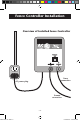
STEP 1: Mount Fence Controller IMPORTANT: Mount inside or in a waterproof enclosure To fence Plastic/PVC pipe To ground Outdoor sheltered installation Inside installation Single screw mounting Double screw mounting USmanual-AC.
STEP 2: Connect Ground and Fence Terminals USmanual-AC.
STEP 3: Connect to Ground System Ground rod clamp (part no.07105-96 or CGR1) Hook-up wire to other ground rods Hook-up wire from fence controller Ground rod (part no.07104-96 or GR8) NOTE: Connect additional ground rods with hook-up wire and ground rod clamps Check ground system reliability • IMPROPER GROUNDING WILL AFFECT THE PERFORMANCE OF YOUR FENCE CONTROLLER! See page 15 for more information about proper grounding. USmanual-AC.
STEP 4: Connect to Fence Line Aluminum/Steel/Poly wire connection Galvanized line clamp (part no. 07110-96) Poly tape connection Poly tape connector clamp (part no. PTCC1) Poly rope connection USmanual-AC.indd 8 Poly rope splicer (part no. PRS2) Check fence system reliability • IMPROPER CONNECTION POINTS WILL AFFECT THE PERFORMANCE OF YOUR FENCE CONTROLLER! • Make sure splices and insulators are sound and secure.
STEP 5: Power Fence Controller NOTE: Fence controller will be outputting voltage at this point – to avoid shock do not touch fence terminal or fence wire. WARNING: For AC-powered fence controllers; do not modify the plug provided with the controller if it doesn’t fit into the outlet. Contact a qualified electrician for proper outlet installation. To reduce the risk of electric shock, these fence controllers have a polarized plug (one blade is wider than the other).
Fence Controller Operation Fence OK • flashes when voltage is on fence line Fence OK • flashes 40-60 times/minute when voltage output is OK • flashes at slower rate when fence line voltage is low USmanual-AC.
Model 8200 Installation/Operation The 8200 (Cow Trainer) is used in stanchion-style dairy barns to train cows to defacate in the gutter. This fence controller powers the T-bar that hangs over the cow’s back, preventing them from hunching. Follow installation steps 1–5 as shown in previous pages. High/Low switch • use HIGH setting for increased voltage when training cows • use LOW setting for cows that are trained USmanual-AC.
Electric Fence Components 1 Fence controller (page 4) 2 6 Gate openings (page 22) 3 7 USmanual-AC.
USmanual-AC.
Electric Fencing Basics Electric fencing is an easy-to-install system for containing animals or keeping them out. A short, safe pulse of electricity creates a psychological barrier that trains animals to avoid the fence. In order for the animal to feel a shock, the voltage produced by the fence controller must penetrate the animal’s hair, hide and hoof. How Electric Fencing Works The system works when an animal provides an electrical path by touching the fence wire and the earth simultaneously.
2 Grounding System Overview of Grounding System An effective ground system consists of: • (3) 6’ to 8’ ground rods (part no. 07104-96 or GR8) • (3) ground rod clamps (part no. 07105-96 or CGR1) • 20 KV insulated hook-up wire (part no. UGC50, UGC250, 1404-92 or 7090-92) Fence Controller Electric Fence Controller 20 KV insulated hook-up wire Ground rod clamps 6' 10 ' First ground rod must be driven within 20’ of fence controller.
Grounding in Dry or Frozen Ground Fence controller Animal makes contact with BOTH hot and ground wire to recieve shock Hot fence wire Ground return wire Hot fence wire Standard ground system Additional ground rod every 1,300’ In dry, sandy or frozen soil a typical grounding system is insufficient because electricity can not flow back to the fence controller. To compensate, create a ground wire return system with one fence wire carrying electricity back to the fence controller’s ground terminal.
3 Fence Posts Fence posts fall into two categories: corner/gate posts, which must withstand tension; and line posts, which simply support the fence line between corner/gate posts. Post material varies and should be selected by fence type. Electric fencing will usually use fewer posts than conventional barbed or woven-wire fencing, making it less expensive and easier to install. Most posts are spaced 12–20 feet apart depending on terrain and animal being controlled.
Post Selection Guide Post Type: Wood Post Plastic Step-in Post Steel T-post, U-post, Y-post Fiberglass T-post/ Rod Post Metal Rod Post X X X X X X Used for: Corner Posts X Line Posts X X X (limited) X Use With Fence Type: X Portable SemiPermanent X Equine X Permanent High Tensile X USmanual-AC.
4 Insulators Insulators isolate the electric fence wire(s) to prevent shorting and electric current leakage, while also keeping the wires properly spaced. Select your insulators to fit the type of post and fence wire you are using. We recommend Red Snap’r® plastic insulators designed for every type of post – wood, T-posts, rod, corner, or chain link fencing. These insulators are available with various front ends to accommodate your selection of steel or poly wire, poly tape or poly rope.
5 Fence Wire Electric fence wire carries the electrical current from the fence controller around the perimeter of the fence. Galvanized steel and aluminum wire carry electricity best. Poly wire, tape and rope have strands of conductive wire twisted or woven into the fabric and are ideal for electric fencing because of its ease-of-use, light weight and visibility. Tip: For equine enthusiasts, we recommend using 1½ inch white poly tape or ¼ inch white poly rope.
To maximize power on the fence, good electrical connections and splices are critical. Splicing Techniques Metal Wire Step 1 Never use loose or single-wrap splices Step 2 Poly Wire Tie any simple knot such as a square knot. Strip back and cut poly strands leaving two inches of conductive wires exposed. Twist or “pigtail” wires together. Poly Rope (using part no. PRS2) Stagger ends of poly rope and tightly secure using poly rope splicer. Poly Tape (using part no.
6 Gate Openings Gate openings can be installed a variety of ways. Typically the same fence wire is used across the opening. If a metal gate or spring gate is used, 20 KV insulated hook-up wire should be used to carry the electrical current under the gate opening. NOTE: Refer to page 8 for information on how to make fence line connections.
7 Lightning/Surge Protection Lightning is one of the main causes of fence controller failure. If a storm is forecast, disconnect your fence controller from the fence in advance, and unplug if it is an AC-powered unit. Using a Zareba Cut-Off Switch (part no. COS1) is a simple way to quickly disconnect your fence controller. If you are in an area with frequent electrical storms, be sure to keep a spare fence controller for backup.
Storm Guard (part no. 01667-92) – Helps protect fence controllers rated at 1 joule of energy output or greater from lightning strikes. Spring Gate Kit (part no. SG1) – Spring coil helps to dissipate lightning surges. AC Surge Suppressor (part no. 1549-96) – Protects AC-powered fence controllers from power surges up to 6,000 volts. Tip: While lightning protection devices can reduce damage by up to 75%, no device provides 100% protection from lightning. USmanual-AC.
Electric Fence Design Design Your Fence Now that you understand how each component works in your fence, sketch your fence layout to get a count of materials you’ll need, including number of posts, wires, insulators, gate openings, etc. Tip: An electric fence line does not have to be constructed in a continuous loop; it also works effectively when dead-ended. Fence controller Corner posts Barn USmanual-AC.
Estimate Your Electric Fence Supplies Use the chart below to get a rough idea of what you’ll need for different size enclosures. Tip: Visit zarebasystems.com to use our online Fence BuilderTM. It will recommend the correct products in the correct amounts for your electric fence.
Fence Configurations By Species Tip: Electric fence systems can be built in any configuration as needed by the end user. The following pages show recommended voltage levels and wire spacings to safely contain different species.
Voltage: 4,000–5,000 v • thick coats/determined animals require more voltage; 4-wire may need to deter predators 7-wire 70" total 6-wire 42" total 10" 10 " 10" 8" 10" 6" 10" 6" 10" 6" 10" 6" 10" Less space between wires deters predators Taller fence to deter goats jumping Voltage: 4,000–5,000 v • determined animals looking for food need 4-wire higher voltage 6-wire 42" total 10" 18"– 24” total Portable/ temporary fences Voltage: 1,000–2,000 v • wires need to be low to ground to deter roo
Voltage: 1,000–2,000 v • smaller animals require closer wire spacing and 4-wire wire close to ground Voltage: 700–1,000 v • use to contain/deter or prevent jumping or 4-wire digging 5-wire 16" total 24" total 6" 4" 6" 3" 3" 6" 3" 6" 3" Height/number of wires depends on size of animal Height/number of wires depends on size of animal Voltage: 4,000–5,000 v • easily trained, but thick coats require 4-wire more voltage 4-wire 46" total 6-wire 42" total 10" 10" 10 " 8" 10 " 16" Boundary fence U
Testing/Troubleshooting 1 Test fence line voltage regularly at the furthest point on the fence from the fence controller to ensure voltage is adequate for the animal being controlled. Adequate voltage reading – fence line OK 2 Inadequate voltage Ensure power supply is sufficient (battery/AC power) Replace/repair battery or AC power to fence controller If power OK, disconnect FENCE and GROUND wires from fence controller, then check voltage output by touching metal part of terminals with tester.
Regular testing and maintenance of your electric fence system is important to assure performance. We recommend Zareba voltage testers DEFT-1 or RSVT8 for this purpose. Tip: Testing voltage by touching the fence line with your hand or a weed is not recommended. In addition, if you do this wearing rubber-soled shoes you will NOT feel a shock. STEP 1: Test the Fence Line Check for adequate voltage at the furthest end of the fence line from the fence controller.
STEP 3: Test Ground System To fence controller (FENCE terminal) 100 yards Push probe into ground Short the fence using a metal bar or wire To fence controller (GROUND terminal) Touch ground rod with tester. If reading is over 400 volts, grounding is inadequate. Add additional ground rods 6 feet apart connected by hook-up wire until reading is under 400 volts.
Fence Controller Warranty 30-DAY FULL WARRANTY Zareba Systems® guarantees your satisfaction. You can return product with its receipt to the place of purchase within 30 days for a full refund. Proof of purchase is required for a full refund. LIMITED WARRANTY This fence controller is warranted for one year from the date of sale to be free from defects of material and workmanship and from damage caused by lightning.
LIMITATION OF DAMAGES The directions for use of this product should be followed carefully. It is impossible to eliminate all risk inherently associated with use of the product. The effectiveness of Zareba Systems® brands of fence controllers may depend on the effectiveness of connections, interruption of power source, accidental grounding of wires, weather conditions, or the manner of use or application, all of which are beyond the control of Zareba Systems® or the seller.
USmanual-AC.
USmanual-AC.indd 36 Woodstream Corp. 69 N. Locust Street Lititz, PA 17543 Contact us: ZarebaSystems.com info@zarebasystems.