
Owner`s manual


Deva IV and Deva V Owner’s Manual
Chapter 4
19
Chapter 4
Pinouts
This section provides the pinouts for the connectors on the Deva. The mating cable connector part num-
ber is also provided for the less common connectors.
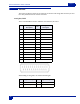
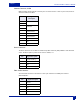
Analog Out, DB25
This is a standard DB-25 connector available at most electronic part stores.
Pin
Signal
Description
Pin
Signal
Description
1 1 + 14 2 -
2 Ground 15 3 +
3 4 - 16 Ground
4 5 + 17 6 -
5 Ground 18 Ground
6 Ground 19 Ground
7 1 - 20 Ground
8 2 + 21 3 -
9 Ground 22 4 +
10 5 - 23 Ground
11 6 + 24 Ground
12 Ground 25 Ground
13 Ground
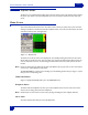
When building an analog cable, use the balanced XLR signals
Pin Signal Description Pin Signal Description
1 Ground 2 In Phase (+) / HOT
3 Out Phase (-) / Cold