
User's Manual


zBoost
®
TRIO Xtreme REACH ZB585X Manual zBoost
®
TRIO Xtreme REACH ZB585X Manual
10 11
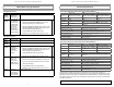
zBoost Base Unit Light Indicators Technical Specifi cations
This product is covered by patent US 7,706,744. Other U.S. and foreign patents pending.
Product Specifi cations for zBoost TRIO Xtreme REACH ZB585X-V
Verizon LTE PCS CEL
Frequency
Uplink: 776—787 MHz
Downlink: 746—757 MHz
Uplink: 1850—1910 MHz
Downlink: 1930—1990 MHz
Uplink: 824—849 MHz
Downlink: 869—894 MHz
Band supported 13
A, D, B, E, F, C A, B, A’, B’
System gain 68 dB 78 dB 69 dB
Output power 3 dBm 4 dBm 3 dBm
Networks LTE (Verizon)
CDMA, GSM, GPRS, EDGE, EVDO, 1xRTT, UMTS,
HSPA, 3G
General Specifi cations
Power Consumption 3W standby; 7W max signal - 2.5A Max
Wall Supply Input ; Voltage 100-240VAC, 50-60 Hz; 5.0VDC
Input and Output Impedance TNC Connector: 50 Ohm; F Connector: 75 Ohm
System Certifi cations FCC Parts 15 & 20, Industry Canada
Base Unit Size and Weight 5” x 7” x 1.25” – 9 oz.
Operating Conditions Indoor Use Only (40° - 105° F)
Coverage (open areas) Up to 5,500 sq. ft.
Product Specifi cations for zBoost TRIO Xtreme REACH ZB585X-A
AT&T LTE PCS CEL
Frequency
Uplink: 704—716 MHz
Downlink: 734—746 MHz
Uplink: 1850—1910 MHz
Downlink: 1930—1990 MHz
Uplink: 824—849 MHz
Downlink: 869—894 MHz
Band supported 17
A, D, B, E, F, C A, B, A’, B’
System gain 68 dB 78 dB 69 dB
Output power 3 dBm 4 dBm 3 dBm
Networks LTE (AT&T)
CDMA, GSM, GPRS, EDGE, EVDO, 1xRTT, UMTS,
HSPA, 3G
General Specifi cations
Power Consumption 3W standby; 7W max signal - 2.5A Max
Wall Supply Input ; Voltage 100-240VAC, 50-60 Hz; 5.0VDC
Input and Output Impedance TNC Connector: 50 Ohm; F Connector: 75 Ohm
System Certifi cations FCC Parts 15 & 20, Industry Canada
Base Unit Size and Weight 5” x 7” x 1.25” – 9 oz.
Operating Conditions Indoor Use Only (40° - 105° F)
Coverage (open areas) Up to 5,500 sq. ft.
The Manufacturer’s rated output power of this equipment is for single carrier operation. For
situations when multiple carrier signals are present, the rating would have to be reduced by 3.5 dB,
especially where the output signal is re-radiated and can cause interference to adjacent band users.
This power reduction is to be by means of input power or gain reduction and not by an attenuator at
the output of the device.
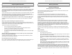
During Initial Power Up
Light Mode Status Solution
Cycle RED,
GREEN,
ORANGE
System is
powering up.
Please allow up
to 30 seconds.
N/A
Flashing
GREEN
BASE UNIT will
fl ash GREEN
once for every
2 dB less than
optimal system
gain. Three
fl ashes or less
indicates the
system will still
operate properly.
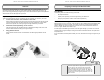
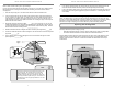
1. Unplug the BASE UNIT power supply.
2. Relocate the EXTERNAL ANTENNA to pick up the
strongest signal from your wireless carrier.
3. Move the EXTERNAL ANTENNA as far away from the
INDOOR ANTENNA as possible, with at least 15 ft. of
vertical separation (height difference).
4. Plug the BASE UNIT power supply back in.
5. Wait 30 secs. for the BASE UNIT to power cycle on.
Solution #1
After Initial Power Up
Light Mode Status Solution
SOLID
GREEN
zBoost is ready. N/A
Flashing
GREEN
zBoost is in use. N/A
SOLID
ORANGE
EXTERNAL
ANTENNA
and INDOOR
ANTENNA
are too close
together.
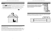
1. Unplug the BASE UNIT power supply.
2. Move the EXTERNAL ANTENNA as far away from the
INDOOR ANTENNA as possible, with at least 15 ft. of
vertical separation (height difference).
3. Plug the BASE UNIT power supply back in.
4. Wait 30 secs. for the BASE UNIT to power cycle on.
Solution #2
SOLID RED Signal from the
carrier’s cell
tower is too
strong for the
BASE UNIT to
operate properly.
1. Unplug the BASE UNIT power supply.
2. Relocate the EXTERNAL ANTENNA to another spot.
3. If you have a directional antenna re-aim it to reduce
carrier signal strength.
4. Plug the BASE UNIT power supply back in.
5. Wait 30 secs. for the BASE UNIT to power cycle on.
Solution #3
Flashing
RED
Excessive
electronic noise
in the system –
the BASE UNIT
will not operate.
^ Refer to Solution #2