Cover Model: DBW1C 1
USER’S MANUAL Revision History Changes to the original manual are listed below: Version Date Description of Version 1.
USER’S MANUAL Important Notice No warranty of any kind is made in regard to this material, including, but not limited to, implied warranties of merchantability or fitness for any particular purpose. We are not liable for any errors contained herein nor for incidental or consequential damages in connection with furnishing, performance or use of this material.
USER’S MANUAL Radio Notice This equipment generates uses and can radiate radio frequency energy. If not installed and used in accordance with the instructions in this manual, it may cause interference to radio communications. Radio and Television Interference Operation of this equipment in a residential area can cause interference to radio or television reception. This can be determined by turning the equipment off and on.
USER’S MANUAL Laser Light Viewing: The scan window is the only aperture through which laser light may be observed from this product. A failure of the scanner engine, while the laser diode continues to emit a laser beam, may cause emission levels to exceed those for safe operation. The scanner has safeguards to prevent this occurrence. If, however, a stationary laser beam is emitted, the failing scanner should be disconnected from its power source immediately.
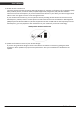
USER’S MANUAL Tips to help improve your wireless network 1. Position the access point (host/dongle) in a relatively empty space at central location. When possible, place the access point in a central location on the high ground (1m or above). If your access point is against an outside wall, the signal will be weak on the other side of the room. 2. Move the access point (host/dongle) off the floor and away from walls and metal objects (such as metal file cabinets).
USER’S MANUAL 3. Reduce wireless interference. The most common wireless technology, 802.11g (wireless-G), operates at a frequency of 2.4 gigahertz (GHz). Many cordless phones, microwave ovens, hospital equipments, refrigerator, LED, and other wireless electronics also use this frequency. If you use these wireless devices in your office, your device might not be able to "hear" the signals over the noise coming from them.
USER’S MANUAL Table of Contents Important Notice..................................................................................................................ii General Handling Precautions..............................................................................ii Guidance for Printing ...........................................................................................ii Laser Safety .........................................................................................................
USER’S MANUAL Visible Indicators Definition for LED function LED1 BLUE/ORANGE LED2 RED/GREEN BT Connected Stable Blue BT Try to or Wait for connect Slow blink Blue BT Transmitting data Fast Blink Blue BT Disconnected Turn OFF Blue (w/ indication Beep) Working in Memory Mode Slow blink Orange Memory nearly FULL(80% FULL) Fast blink Orange Memory FULL Stable Orange(w/Caution Beep) Power ON Stable RED Good Read Blink once Green w/Beep Battery Low (<30%) Slow Blink Red Battery Very Low (<15%) Fast Blink Red
USER’S MANUAL ACK/NAK Protocol or Frame Packing When scanner is in SPP Master/Slave mode, and add in the data protocol or packing could confirm the data reliability.
USER’S MANUAL Scanner to Remote Application Data Format of Packet To send a data (barcode) to the remote application, the scanner has to encapsulate it: EAH (Header) Size of payload 1 byte 1 byte FEH (Format Byte) 1 byte Data ID Data Barcode Type 1 byte Varies 1 byte AEH (End of Byte) 1 byte Reserved Byte 1 byte Title Header Character (EAH) Definition The character ID at the head of every data. It has to start with EAH.
USER’S MANUAL Barcode Type Table Code Value Code39 0x11 Codabar 0x01 Code128 0x03 Interleaved 2/5 0x02 Code93 0x06 UPC-E 0x14 UPC-A 0x24 EAN-8 0x34 EAN-13 0x44 Chinese Post Code 0x05 MSI 0x07 Firmware Update To update the firmware, scan the Start of Configuration barcode then scan Dongle USB Update or Scanner USB Update to enter Firmware Update mode. To exit Firmware Update mode without updating, please remove and re-insert the battery.
USER’S MANUAL Programming Guide Program Procedure Using Barcode Manual 1. Power up the scanner. 2. Scan the Start of Configuration barcode. 3. Scan the barcode for the desired feature. Multiple features can be enabled/disabled before scanning the End of Configuration barcode. 4. Scan the End of Configuration barcode and save the new configuration. Power off and on the scanner when the setting is done. 5.
USER’S MANUAL Default Parameters The factory default setting table gives the default settings of all the programmable parameters. The default settings will be restored whenever the "Reset" programming label is scanned and the scanner is in programming mode. Default values are highlighted in grey background in the settings.
USER’S MANUAL Standard 2 of 5 Industrial 2 of 5 GS1 DataBar Disable Disable Disable Beeper Sound Frequency Duration Operating Parameter Scan mode Stand mode Header and trailer Inter-message delay Inter-character delay Code Identifiers Identifier code as ZEBEX standard Identifier code as AIM standard Code 39 identifier code ITF 2 of 5 identifier code Chinese post code identifier code UPC-A identifier code UPC-E identifier code EAN-13 identifier code EAN-8 identifier code Codabar identifier code Code 128 id
USER’S MANUAL Default Data Transmit Format Code EAN-13 EAN-8 UPCA UPCE CODE128 EAN128 CODE39 CODABAR INTERLEAVED 2/5 CHINESE POST CODE CODE93 MSI 8 Message format D1 D2 D3 D4 D5 D6 D7 D8 D9 D10 D11 D12 D13 D1 D2 D3 D4 D5 D6 D7 D8 D1 D2 D3 D4 D5 D6 D7 D8 D9 D10 D11 D12 D1 D2 D3 D4 D5 D6 D7 D8 D1-Dx (default 3~62) C1 D1-Dx (default 3~62) D1-Dx (default 3~62) D1-Dx (default 6~32) D1-Dx (default 6~32) D1-Dx (default 8~32) D1-Dx (default 3~32) D1-Dx (default 6~32) Di Bar Watch
USER’S MANUAL Connecting to a Host The scanner provides several data transmit methods to communicate with the host. User may select the method according to their preferences. Read this section to learn the setups for connecting to different hosts. Start Of Configuration USB Online Mode The scanner connects directly to a USB host to recharge and transmit data. You may enable or disable the functions using the following settings. Disable USB communication Disable USB communication.
USER’S MANUAL Start Of Configuration Dongle Host Mode The scanner communicates with the host through the dongle. Typically, scanner and dongle in the same delivery box are paired and corresponded to host interface in factory. To check if the scanner is paired to the dongle, check the scanner LED for slow blue flash and check the top dongle LED for steady blue light. If scanner LED and dongle LED are both flashing blue, follow the steps below to radio connect the scanner and dongle. Dongle Host Pairing 1.
USER’S MANUAL Start Of Configuration Wireless Mode The scanner connects to the host via wireless connection. You may select SPP Master or SPP Slave for PC connection or select HID mode and Smart phone mode for smart phone connection. SPP Slave Mode In this mode, the scanner connects to the host /PC via wireless connection and performs like there’s a serial connection. In SPP Slave mode, the scanner is discoverable from a remote device and it can request the scanner for connection.
USER’S MANUAL Connect to PC [Window] To connect a wireless device to Window XP for the first time: 1. Turn on the host computer and activate its wireless connection. 2. Select “Add wireless device”. Or open the dialog BT devices and click “Add”. 3. 4. 12 Power on the scanner and program it with “Scanner SPP Slave enable” label from the previous page. In COM Ports page, click “Add”. This will open the Add COM port window.
USER’S MANUAL 5. Select “Outgoing (computer initiate the connection)”, and then click “Browse”. 6. The scanner should be on the list of discoverable devices. The default name of the scanner is “TBD”. Select it and click “OK”.
USER’S MANUAL 14 7. Write down the COM port number for later use. 8. Select the Device tab to go back to the device page.
USER’S MANUAL 9. A message should appear in the Windows Taskbar telling you a Bluetooth device is attempting to connect. Click on the message to open Add Bluetooth Device Wizard. 10. Enter the pin code in the Add Bluetooth Device Wizard and click “Next”. The default pin code is “12345678. 11. 13. Click “Ok” when the connection is established. 12. Open HyperTerminal or other serial port programs and select the COM port you wrote down in the previous step and click “OK”.
USER’S MANUAL SPP Master Mode To connect a wireless device to Window XP for the first time: 1. Turn on the host computer and activate its wireless connection. 2. Select “Add wireless device”. Or open the dialog BT devices and click “Add”. 3. 4. 16 Power on the scanner and program it with “Scanner SPP Slave enable” label from the previous page. In COM Ports page, click “Add”. This will open the Add COM port window.
USER’S MANUAL 5. Select “Incoming (scanner initiate the connection)”, and then click “OK”. 6. Write down the COM port number for later use.
USER’S MANUAL 7. 9. Select the Device tab to go back to the device page. Scan “Set device address” to set the address. Set device address (SPP Master only) Set device address for SPP Master connection. 10. Use the ASCII table in Programming Guide to input the 12 digit device address. For example: if the address is “011B1345600”, scan “0”, “0”, “1”, “1”, “B”, “1”, “3”, “4”, “5”, “6”, “0”, “0” from ASCII barcode labels. 11. Scan “Confirm Setting” to store the address.
USER’S MANUAL 14. A message should appear in the Windows Taskbar telling you a Bluetooth device is attempting to connect. Click on the message to open Add Bluetooth Device Wizard. 15. Enter the pin code in the Add Bluetooth Device Wizard and click “Next”. The default pin code is “12345678. 16. 13. Click “Ok” when the connection is established. 17. Open HyperTerminal or other serial port programs and select the COM port you wrote down in the previous step and click “OK”.
USER’S MANUAL Start Of Configuration HID mode In HID mode, the scanner connects to the host /PC via wireless connection and performs like there’s a keyboard connection. The scanner initiates the connection to the remote device. 1. Power on the scanner and program it with “HID Mode”. To connect a smart mobile phone (for example, iPhone, Android), the Smart phone mode must also be enabled. Power off the scanner when the setting is done.
USER’S MANUAL Start Of Configuration Setting Pin Code 1. To change the pin code, use the “Set pin code” setting. Default is “12345678”. 2. Use the ASCII table in Programming Guide to input the new code (must be at least 4 digits and not more than 8 numeric digits). 3. Scan “Save Setting” to store the pin code. Set pin code (SPP Master only) Set pin code Confirm Setting (for address and pin code setting required) Please check the User’s Manual from your PC for device address and pin code.
USER’S MANUAL Start Of Configuration Setting Name 1. To change the name displayed when the scanner is discovered, scan the “Friendly device name set” label. Default name is “Dibar”. 2. Use the ASCII table in Programming Guide to input the name (Max.12 digits). 3. Scan “Confirm Setting” to store the new name. Friendly device name set Change the display name when scanner is discovered.
USER’S MANUAL Start Of Configuration Secure Simple Pairing The scanner connects to the host via SPP Slave, SPP Master, HID, HID Keyboard, or HID Multi Media Keyboard mode without pin code when the host supports it.
USER’S MANUAL Start Of Configuration Data Transmit Method The data transfer method includes three types: Normal (default), Out-of-Range Mode, and Batch Mode. Users may modify this setting according to their preferences. Normal When the scanner is within the connection range, the scanned data will be transferred to the host computer immediately. If the scanner is out of its connecting range, the scanner does not send or store any data. Batch mode is disabled.
USER’S MANUAL Start Of Configuration Batch Mode Whether within the connection range or not, in batch mode, the scanner stores all scanned data that will be transferred to the host computer after scanning “Send Batch Data” label. Number of storable bar codes = 61,365 bytes of memory / (number of characters in the bar code +2) Batch mode Note: Scanner LED indicator will not flash while waiting for connection in this mode. Clearing Batch Use the settings in this section to clear the stored data.
USER’S MANUAL Start Of Configuration Batch Transfer Use the settings in this section to setup batch transfer. Send Batch Data By Scanning Label Send Batch Data on line USB cable contact Scanning this label automatically exits you from the Programming Mode. Press and hold the trigger for over 1 second to send the data. Data is ready to be transferred upon USB connection. Press and hold the trigger for over 1 second to send the data.
USER’S MANUAL System Function Settings Default values are highlighted in grey background.
USER’S MANUAL Start Of Configuration Barcode Value Description Display firmware version Abort (exit programming mode without any updates) Scan Mode Trigger mode The scanner becomes inactive as soon as the data is transmitted. It must be triggered to become active again. Auto scan mode The scanner is still active after the data is transmitted but the successive transmission of the same barcode is not allowed when the trigger switch is pressed again.
USER’S MANUAL Start Of Configuration Radio Communication Setting Dongle Host mode Dongle Host mode enable Enable dongle mode with this setup. Unlock pairing mode In this mode, the scanner can pair with another dongle when disconnected. Lock pairing mode. In this mode, the scanner can not pair with another dongle. Undo pairing Undo the pairing between the dongle and the scanner.
USER’S MANUAL Start Of Configuration HID mode HID mode (Combo keyboard) For Apple mode SPP Master/Slave mode Scanner SPP Master enable SPP Master (Connect wireless address “BxxxxxxxxxxxxT” in CODE39 format) Scanner SPP Slave enable Setting wireless address (SPP Master only) Set PIN code (SPP Master only) Device Setting Show device address after friendly name enabled Enable showing device address xx:xx:xx after device name during discovery Show device address after device friendly name disabled Disable sh
USER’S MANUAL Start Of Configuration Default Device name Friendly device name set Delete pin code Confirm Setting (for address, device name, and pin code setting required) Required Pair with slave (SPP Master) Discover enable Discover disable Encryption enable Encryption disable Data communication without protocol Data communication with ACK/NAK protocol Data communication with Packing protocol End Of Configuration Di Bar Watch 31
USER’S MANUAL Start Of Configuration Data Transmit Mode Data transmit normal Out of range buffer enable Batch mode Send Batch Data By Scanning Label Clear batch data after send Clear batch data by scanning “Delete batch data” label Delete batch data Send Batch Data on line USB cable contact.
USER’S MANUAL Start Of Configuration Radio protocol communication parameter Radio protocol timeout= 3 sec Radio protocol timeout= 5 sec Radio protocol timeout =8 sec Radio protocol timeout= 10 sec Radio protocol timeout =13 sec Radio protocol timeout =16 sec Radio protocol timeout= 20 sec End Of Configuration Di Bar Watch 33
USER’S MANUAL Start Of Configuration Power off timeout parameter Power off timeout=5 min Power off timeout=10 min Power off timeout=20 min Power off timeout=30 min Power off timeout=1 hr Power Off timeout : 2 hr Power Off timeout : 4 hr Power Off timeout : 6 hr Power Off timeout : 8 hr End Of Configuration 34 Di Bar Watch
USER’S MANUAL Start Of Configuration Power Always On Power off by scanning this label Link beeper enable Link beeper disable Power-up beeper enable Power-up beeper disable Same Code Delay 50 msec 100 msec 200 msec 300 msec End Of Configuration Di Bar Watch 35
USER’S MANUAL Start Of Configuration 400 msec 500 msec 600 msec 700 msec 800 msec 1000 msec Infinite End Of Configuration 36 Di Bar Watch
USER’S MANUAL Start Of Configuration Operation Function Setting Good Read Beeper Tone Selection Medium beeper tone High beeper tone Low beeper tone Speaker disable End Of Configuration Di Bar Watch 37
USER’S MANUAL Start Of Configuration Beeper duration Selection Long Medium Short Ultra Short Ultra Long End Of Configuration 38 Di Bar Watch
USER’S MANUAL Start Of Configuration Inter Character Delay 0 ms 2 ms 5 ms 10 ms 20 ms 50 ms Inter Message Delay 0 ms 100 ms 500 ms 1000 ms End Of Configuration Di Bar Watch 39
USER’S MANUAL Start Of Configuration Interface Settings RS-232C Interface Setting Start Of Configuration Message Terminator RS-232 message terminator—none RS-232 message terminator—CR/LF RS-232 message terminator—CR RS-232 message terminator—LF RS-232 message terminator—H tab RS-232 message terminator—STX/ETX RS-232 message terminator—EOT End Of Configuration 40 Di Bar Watch
USER’S MANUAL Start Of Configuration USB Interface Setting USB Setting International Keyboard mode ( ALT method) Keyboard language support---USA Keyboard language support---UK send scan code Keyboard language support---GERMANY Keyboard language support---FRENCH send scan code Keyboard language support---SPANISH send scan code Keyboard language support---ITALIAN send scan code Keyboard language support---Switzerland send scan code Keyboard language support---Belgium send scan code Keyboard language support-
USER’S MANUAL Start Of Configuration Message Terminator Keyboard terminator---none Keyboard terminator---Enter Keyboard terminator---H-TAB End Of Configuration 42 Di Bar Watch
USER’S MANUAL Start Of Configuration Smart Phone Software Keypad Control Setting Smart Phone Software Keypad Control Multi-media keyboard mode This option enables Multi-media keyboard mode Software keypad enable/disable This option enable or disable Software keypad To enable/disable Software keyboard: 1. 2. 3. 4. 5. Scan the Start Of Configuration barcode. Scan the Multi-media keyboard mode barcode. Scan the End Of Configuration barcode. Connect the scanner with a smart phone.
USER’S MANUAL Start Of Configuration The Symbologies Codabar Parameter Setting Barcode Value RC02 Barcode Label Description Codabar enable RD02 Codabar disable CB05 Codabar start/stop character transmission-none CB06 Codabar start/stop character transmission-A,B,C,D CB07 Codabar start/stop character transmission- DC1~DC4 CB08 Codabar start/stop character transmission- a/t,b/n,c/*,d/e CB09 Codabar maximum length setting CB10 Codabar minimum length setting SET Confirm to save this setting (
USER’S MANUAL Start Of Configuration Barcode Value CB13 Barcode Label Description No check character CB14 Validate modulo 16,but don’t transmit CB15 Validate modulo 16 and transmit DC50 Codabar data redundant check=off DC51 Codabar data redundant check=1 DC52 Codabar data redundant check=2 DC53 Codabar data redundant check=3 End Of Configuration Di Bar Watch 45
USER’S MANUAL Start Of Configuration Code 39 Parameter Setting Barcode Value RC01 Barcode Label Description Code 39 enable RD01 Code 39 disable RC13 Code 32 enable RD13 Code 32 disable DC00 Code 39 data redundant check=off DC01 Code 39 data redundant check=1 DC02 Code 39 data redundant check=2 DC03 Code 39 data redundant check=3 3901 Standard code 39 3902 Full ASCII code 39 3903 Code 39 start/stop character transmission 3904 Code 39 start/stop character without transmission End Of C
USER’S MANUAL Start Of Configuration Barcode Value 3905 Barcode Label Description Code 39 check digit calculate and transmit 3906 Code 39 check digit calculate but without transmit 3907 No check character 3908 Code 39 maximum length setting 3909 Code 39 minimum length setting SET Confirm to save this setting (required for reading full ASCII table and length setting) 3912 Code 32 (Italian pharmacy) transmit “A” character 3913 Code 32 (Italian pharmacy) without transmit ”A” character End Of
USER’S MANUAL Start Of Configuration Code 93 Parameter Setting Barcode Value RC08 Barcode Label Description Code 93 enable RD08 Code 93 disable DC30 Code 93 data redundant check=off DC31 Code 93 data redundant check=1 DC32 Code 93 data redundant check=2 DC33 Code 93 data redundant check=3 9301 Code 93 maximum length setting 9302 Code 93 minimum length setting SET Confirm to save this setting (required for reading full ASCII table and length setting) 9303 Code 93 check digit calculate but
USER’S MANUAL Start Of Configuration Code 128 Parameter Setting Barcode Value RC06 Barcode Label Description Code 128 enable RD06 Code 128 disable RC10 EAN-128 enable RD10 EAN-128 disable DC40 Code 128 data redundant check=off DC41 Code 128 data redundant check=1 DC42 Code 128 data redundant check=2 DC43 Code 128 data redundant check=3 1803 No check character 1804 Calculate but not transmit 1805 Calculate and transmit 1806 Code 128 maximum length setting 1807 Code 128 minimum lengt
USER’S MANUAL Start Of Configuration Chinese Post Code Parameter Setting Barcode Value RC05 Description Barcode Label Chinese post code enable RD05 Chinese post code disable DC60 Chinese post code data redundant check=off DC61 Chinese post code data redundant check=1 DC62 Chinese post code data redundant check=2 DC63 Chinese post code data redundant check=3 SZ01 Chinese post code maximum length setting SZ02 Chinese post code minimum length setting SET Confirm to save this setting (require
USER’S MANUAL Start Of Configuration MSI/Plessy Parameter Setting Barcode Value RC14 Description Barcode Label MSI enable RD14 MSI disable DC70 MSI data redundant check= off DC71 MSI data redundant check=1 DC72 MSI data redundant check=2 DC73 MSI data redundant check=3 MS01 MSI/Plessy maximum length setting MS02 MSI/Plessy minimum length setting SET MS03 MS04 MS05 MS06 MS07 MS08 Confirm to save this setting (required for reading full ASCII table and length setting) MSI/Plessy double check
USER’S MANUAL Start Of Configuration Code 11 Interface Setting Barcode Value RC07 Barcode Label Description Code 11 enable RD07 Code 11 disable 1101 Code 11 maximum length setting 1102 Code 11 minimum length setting SET Confirm to save this setting (required for reading full ASCII table and length setting) 1103 Code 11 one check digit verification 1104 Code 11 two check digit verification 1105 Two Check for Code 11 check digit if code length is longer than 10 characters 1106 Disable verifi
USER’S MANUAL Start Of Configuration ITF 2 of 5 Parameter Setting Barcode Value RC04 Barcode Label Description ITF 2 of 5 enable RD04 ITF 2 of 5 disable RC09 IATA code enable RD09 IATA disable DC80 ITF 25 data redundant check=off DC81 ITF25 data redundant check=1 DC82 ITF25 data redundant check=2 DC83 ITF25 data redundant check=3 IT03 ITF 2 of 5 no check character IT04 ITF 2 of 5 check digit calculate and transmit IT05 ITF 2 of 5 check digit calculate but without transmit End Of Confi
USER’S MANUAL Start Of Configuration Barcode Value IT01 Barcode Label Description ITF 2 of 5 code maximum length setting IT02 ITF 2 of 5 code minimum length setting IT06 ITF 2 of 5 one fixed length setting IT07 ITF 2 of 5 two fixed length setting SET Confirm to save this setting (required for reading full ASCII table and length setting) IT08 ITF 2 of 5 length variable End Of Configuration 54 Di Bar Watch
USER’S MANUAL Start Of Configuration Standard 2 of 5 Parameter Setting Barcode Value RC22 Description Barcode Label Standard 2 of 5 code enable RD22 Standard 2 of 5 code disable D051 Standard 2 of 5 code maximum length setting D052 Standard 2 of 5 code minimum length setting SET Confirm to save this setting (required for reading full ASCII table and length setting) D053 Standard 2 of 5 code no check character D054 Standard 2 of 5 code check digit calculate and transmit D055 Standard 2 of 5
USER’S MANUAL Start Of Configuration Industrial 2 of 5 Parameter Setting Barcode Value RC21 Description Barcode Label Industrial 2 of 5 code enable RD21 Industrial 2 of 5 code disable D251 Industrial 2 of 5 code maximum length setting D252 Industrial 2 of 5 code minimum length setting SET Confirm to save this setting (required for reading full ASCII table and length setting) D253 Industrial 2 of 5 code no check character D254 Industrial 2 of 5 code check digit calculate and transmit D255 In
USER’S MANUAL Start Of Configuration UPC/EAN/JAN Parameter Setting Barcode Value RC11 Description Barcode Label EAN convert to ISSN/ISBN enable RD11 EAN convert to ISSN/ISBN disable RC03 UPC/EAN/JAN enable RD03 UPC/EAN/JAN disable UE01 UPC/EAN/JAN all enable UE02 EAN-8 or EAN-13 enable UE03 UPC-A and EAN-13 enable UE04 UPC-A and UPC-E enable UE05 UPC-A enable UE06 UPC-E enable UE07 EAN-13 enable UE08 EAN-8 enable UE09 UPC/EAN Addendum disable End Of Configuration Di Bar Watch 57
USER’S MANUAL Start Of Configuration Barcode Value UE10 Barcode Label Description Add on 5 only UE11 Add on 2 only UE12 Add on 2 or 5 UE13 Force UPC-E to UPC-A format enable UE14 Force UPC-E to UPC-A format disable UE15 Force UPC-A to EAN-13 format enable UE16 Force UPC-A to EAN-13 format disable UE44 Force EAN-8 to EAN-13 format enable UE45 Force EAN-8 to EAN-13 format disable UE17 Transmit UPC-A check digit enable UE18 Transmit UPC-A check digit disable UE19 Transmit UPC-E leading
USER’S MANUAL Start Of Configuration Barcode Value UE23 Barcode Label Description Transmit EAN-8 check digit enable UE24 Transmit EAN-8 check digit disable UE25 Transmit EAN-13 check digit enable UE26 Transmit EAN-13 check digit disable UE27 Transmit UPC-A leading character enable UE28 Transmit UPC-A leading character disable UE30 Add-on format with separator UE31 Add-on format without separator UE60 EAN-13 country code first “0” can be transmitted UE61 EAN-13 country code first:”0” can
USER’S MANUAL Start Of Configuration Barcode Value DC12 Barcode Label Description UPC-A data redundant check=2 DC13 UPC-A data redundant check=3 DC14 UPC-E data redundant check=off DC15 UPC-E data redundant check=1 DC16 UPC-E data redundant check=2 DC17 UPC-E data redundant check=3 DC20 EAN-13 data redundant check=off DC21 EAN-13 data redundant check=1 DC22 EAN-13 data redundant check=2 DC23 EAN-13 data redundant check=3 DC24 EAN-8 data redundant check=off DC25 EAN-8 data redundant
USER’S MANUAL Start Of Configuration UE35 EAN/UPC +add-on mandatory for 978/977 bookland (Supplement requirement, not sent for other) UE38 EAN/UPC +addon mandatory for 978/977 bookland (Supplement requirement, optional for other) UE42 EAN/UPC +addon mandatory for 491 Japanese bookland (Supplement requirement, not sent for other) UE43 EAN/UPC +addon mandatory 491 Japanese bookland (Supplement requirement, optional for other) End Of Configuration Di Bar Watch 61
USER’S MANUAL Start Of Configuration Telepen Parameter Setting Barcode Value RC25 Barcode Label Description Telepen enable RD25 Telepen disable TE03 Telepen numeric mode enable TE04 AIM Telepen enable End Of Configuration 62 Di Bar Watch
USER’S MANUAL Start Of Configuration Matrix 2 of 5 Parameter Setting Barcode Value RC12 Description Barcode Label Matrix 2 of 5 enable RD12 Matrix 2 of 5 disable D151 Matrix 2 of 5 maximum length setting D152 Matrix 2 of 5 minimum length setting SET Confirm to save this setting (required for reading full ASCII table and length setting) D153 Matrix 2 of 5 no check character D154 Matrix 2 of 5 check digit calculate and transmit D155 Matrix 2 of 5 check digit calculate but without transmission
USER’S MANUAL Start Of Configuration GS1 DataBar Parameter Setting There are 7 kinds of barcodes in the GS1 DataBar family and they are categorized into three groups. Barcode types in the same group use the same barcodes for setting.
USER’S MANUAL Start Of Configuration GS1 DataBar Limited (Formally RSS Limited) Barcode Value RC16 Barcode Label Description GS1 DataBar Limited enable RD16 GS1 DataBar Limited disable SS10 Transmit GS1 DataBar Limited check digit SS11 Don’t transmit GS1 DataBar Limited check digit SS12 Transmit GS1 DataBar limited application ID (01) SS13 Do not transmit GS1 DataBar limited application ID End Of Configuration Di Bar Watch 65
USER’S MANUAL Start Of Configuration GS1 DataBar Expanded (Formally RSS Expanded) Barcode Value RC17 Barcode Label Description GS1 DataBar Expanded enable RD17 GS1 DataBar Expanded disable SS07 GS1 DataBar Expanded/EAN-128 emulation enable SS06 GS1 DataBar Expanded/EAN-128 emulation disable SS08 GS1 DataBar Expanded check digital enable SS09 GS1 DataBar Expanded check digital disable SS16 Transmit GS1 DataBar Expanded application ID (01) SS17 Do not transmit GS1 DataBar Expanded application
USER’S MANUAL Start Of Configuration Data Editing Identifier Code Barcode Value IS00 Barcode Label Description Disable identifier code IS01 Enable identifier code table as factory standard IS03 Enable identifier code table as AIM standard.
USER’S MANUAL Start Of Configuration Barcode Value CI08 Barcode Label Description Codabar identifier code setting CI09 Code 128 identifier code setting CI10 Code 93 identifier code setting CI11 MSI identifier code setting CI12 GS1 DataBar Omnidirectional identifier code setting CI13 GS1 DataBar Limited identifier code setting CI14 GS1 DataBar expanded identifier code setting CI15 Industrial 2 of 5 identifier code setting CI16 Code 11 Identifier code setting CI17 Standard 2 of 5 identifi
USER’S MANUAL Start Of Configuration Header and Trailer Barcode Value CP11 CP12 HT01 HT02 HT03 HT04 SET Barcode Label Description Add code length as header enable (2 digits) Add code length as header disable (2 digits) Header (Preamble) Trailer (Postamble) Truncate header character Truncate trailer character Confirm to save this setting (required for reading full ASCII table and length setting) End Of Configuration Di Bar Watch 69
USER’S MANUAL Start Of Configuration Full ASCII Code 39 Table Code 39 Hexa code ASCII Code 39 ASCII Hexacode Full ASCII ---NUL 00 Full ASCII ---SI Function key-----“Shift” 0F Full ASCII ---SOH Function key-----“Ins” 01 10 Full ASCII ---STX Function key-----“Del” 02 Full ASCII ---DLE Function key----“5(num)” Full ASCII ---DC1 Function key-----“F1” Full ASCII ---ETX Function key-----“Home” 03 Full ASCII ---DC2 Function key-----“F2” 12 Full ASCII ---EOT Function key-----“End” 04 Full ASC
USER’S MANUAL Start Of Configuration Full ASCII Code 39 Table (continued) HexaCode 39 ASCII code Code 39 ASCII Hexacode Full ASCII ---RS Function key-----“CTL(L)” 1E Full ASCII ---- 2D Full ASCII ---US Function key-----“ALT(L)” 1F Full ASCII ---.
USER’S MANUAL Start Of Configuration Full ASCII Code 39 Table (continued) Code 39 ASCII Hexacode Code 39 ASCII Hexacode Full ASCII ---< 3C Full ASCII ---K 4B Full ASCII ---= 3D Full ASCII ---L 4C Full ASCII ---> 3E Full ASCII ---M 4D Full ASCII ---? 3F Full ASCII ---N 4E Full ASCII ---@ 40 Full ASCII ---O 4F Full ASCII ---A 41 Full ASCII ---P 50 Full ASCII ---B 42 Full ASCII ---Q 51 Full ASCII ---C 43 Full ASCII ---R 52 Full ASCII ---D 44 Full ASCII ---S 53 Full AS
USER’S MANUAL Start Of Configuration Full ASCII Code 39 Table (continued) HexaCode 39 ASCII code Code 39 ASCII Hexacode Full ASCII ---Z 5A Full ASCII ---i 69 Full ASCII ---[ 5B Full ASCII ---j 6A Full ASCII ---\ 5C Full ASCII ---k 6B Full ASCII ---] 5D Full ASCII ---l 6C Full ASCII ---^ 5E Full ASCII ---m 6D Full ASCII ---_ 5F Full ASCII ---n 6E Full ASCII ---` 60 Full ASCII ---o 6F Full ASCII ---a 61 Full ASCII ---p 70 Full ASCII ---b 62 Full ASCII ---q 71 Full ASCII
USER’S MANUAL Start Of Configuration Full ASCII Code 39 Table (continued) HexaCode 39 ASCII code Code 39 ASCII Hexacode Full ASCII ---x 78 Full ASCII ---| 7C Full ASCII ---y 79 Full ASCII ---} 7D Full ASCII ---z 7A Full ASCII ---~ 7E Full ASCII ---{ 7B Full ASCII ---DEL 7F End Of Configuration 74 Di Bar Watch
USER’S MANUAL Appendix 1: USB Virtual COM Driver Installation Contact your distributor to get the driver and follow the steps below to enable USB virtual COM port. 1. Connect the handheld scanner and the host (e.g. a PC) with a USB interface cable. 2. Enable USB virtual COM port with programming barcode on page 32. 3. After the programming, the host would request driver installation. Browse your files to locate the driver and start installation. 4.
USER’S MANUAL Appendix 2: Barcode Length Setting Introduction The length of a barcode is the number of characters it contains, including check digits. As listed in the Default Parameters section, each barcode type has different default length. You may change the setting by the following procedure. To set up barcode length, the paramours to be determined are barcode type and the desired barcode length. Barcode length is consisted of 2 digits. For numbers smaller than 10, you need to add a “0” in the front.
Federal Communication Commission Interference Statement This equipment has been tested and found to comply with the limits for a Class B digital device, pursuant to Part 15 of the FCC Rules. These limits are designed to provide reasonable protection against harmful interference in a residential installation. This equipment generates, uses and can radiate radio frequency energy and, if not installed and used in accordance with the instructions, may cause harmful interference to radio communications.