
Install Instructions
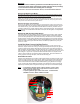
Table Of Contents

Warnings:
• This kit should be installed by qualified and trained HVAC/R personnel only!
• Disconnect supply voltage and discharge system capacitors before proceeding!
• Follow all electrical codes when working with line voltages!
repair will help.
Remove the Old Current-Limiting Device:
Use safety glasses. Pre-heat soldering iron. The Device often has the marking “RT01” stamped
on the top of many circuit boards. Mark the Device’s leads (on bottom of board) with a felt-tip
pen to more easily identify them. Next, heat those leads (on the bottom of the circuit board) and
wiggle the device out of the board, alternately heating and wiggling each leg until the old Device
is removed. Now, on a suitable workbench or other undamageable surface, clear the holes where
the Device’s leads go through the board. Be careful, hot solder may splatter when you rap the
distance to keep the device from burning or scorching the board (because the part can get hot in
normal use.) Bend over the leads to follow the foil on the back of the circuit board, trimming the
leads if necessary, and solder them to the board with rosin-core or “electronic” solder (never use
acid-core solder on electronic boards or parts.) Do not spare the solder, but do not put on so much
that it “bridges” or “jumps” from one pad on the board to another. When cool, inspect to make
certain no excess solder has connected any leads or pads together. Be sure that Device is not
‘leaning’ against or touching other parts; it can become hot during use.
Reassemble and Test:
Install the circuit board back into the module, making certain that the connecting wires do not get
pinched or caught near the screw or snap-mounts. Snap the circuit board onto its mating plastic
mount. Re-install and tighten the 2 Phillips-head screws. Position Module near motor and plug
3-wire connector back into module. Re-attach Module to Motor, paying attention to the keying
“hump” and “slot” that orient the Module one direction only. Install the two mounting screws and
tighten firmly. Re-attach power and signal harness plugs. Power up the unit and test completely.
Notes: • A normal Device measures about 1-5 Ohms resistance across its leads.
• A typical result of a failure will be a high resistance across the Device’s
leads, causing no current to flow.
• To protect against this type of failure in the future - use Zebra HVAC’s
ECM Motor Protectors; Models VZPRO and X13PR.
board on a surface.
Install the New Current-Limiting Device:
Insert the new device until it is no closer than 1/2” from the board; it will be soldered at this
Kit Content: 1 Over-Current Protection Device; Circuit Board Mount Releaser
Remove the Module from Motor:
Disconnect all power to system. Disconnect power and signal harness plugs from motor.
Wait 5 full minutes for capacitors to discharge before proceeding! Many modules can be
removed from the motor without removing motor from fan unit. (Some Units may have to be slid
partway out of handler to access mounting screws.) Remove the two module mounting screws,
and unplug the 3-wire internal connector by squeezing the latch first, then pulling the connector
away from the circuit board. Do NOT pull the wires!
Remove the Upper Circuit Board:
Remove the two phillips-head Screws holding the circuit board to the module. Press down firmly
on the plastic board-mount clip (with the included mount-releaser) to allow the board to come out
of the module housing. (The circuit board will still be attached to module by at least 2 wires; do
not stress or stretch them.) Visually inspect the parts on the board for damage, and for damage to
either side of the circuit board itself. If the board or other parts are damaged, it is unlikely that this
Typical
Device
>>>
<<
Board
Mount
Clip