
User Guide


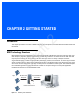
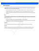
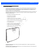


Table Of Contents
- Warranty
- Revision History
- About This Guide
- Quick Start
- Getting Started
- Installation and Communication
- Administrator Console
- Introduction
- Connecting to the Reader
- Administrator Console Login
- Reader Administrator Console
- Status
- Reader Statistics
- Configure Reader
- Read Tags
- Communication Settings
- System Time Management
- IPV6 IP Sec
- Change Password
- GPIO
- Applications
- Reader Profiles
- Firmware Version/Update
- Commit/Discard
- System Log
- Reader Diagnostics
- Shutdown
- Wi-Fi Configuration
- Application Development
- Firmware Upgrade
- Troubleshooting
- Technical Specifications
- Static IP Configuration
- RF Air Link Configuration
- Connecting Wi-Fi and Bluetooth Dongles
- Copying Files To and From the Reader
- Data Protection

Getting Started 2 - 5
FX7500 RFID Reader Rear Panel
FX7500 RFID Readers LEDs
The reader LEDs indicate reader status as described in Table 2-2. For the LED boot up sequence see System
Start-up/Boot LED Sequence on page 3-11.
Figure 2-5
FX7500 RFID Readers LEDs
Table 2-1
Rear Panel Descriptions
Port Description
Antenna Ports
(Reverse TNC)
Two port version: Connect up to two antennas.
Four port version: Connect up to four antennas.
See
Table A-1 on page A-2
for the maximum antenna gains and RF output powers for both
US/Canada and EU. See
Connecting Antennas on page 3-4
for connection information.
Reset To reset the reader insert a paper clip into the reset hole, press and hold the reset button for
not more than 2 seconds. This resets the reader, but retains the user ID and password.
GPIO See
GPIO Interface Connection on page 3-9
for more information.
USB Client The USB client port supports (by default) a network mode of operation. This enables a
secondary network interface as a virtual adapter over USB.
Advanced users can create a custom communication protocol on the USB port.
See
USB
Connection on page 3-6
for connection information.
USB Host Use the USB host port to connect USB devices such as WiFi / Bluetooth over USB dongles
and flash memory drives.
10/100BaseT
Ethernet
Insert a standard RJ45 Ethernet cable to connect to an Ethernet network with or without
POE capability, or to a local computer. See
Ethernet Connection on page 3-5
for
connection information.
Power DC connector connects to a Zebra approved power supply AC adapter (varies depending
on the country). Maximum power 24 VDC, 1.2 A. See
Powering the Reader on page 3-10
for connection information.
PWR A CT V STAT
APP
Draft 2