___________________________________________________________________________ Infrastructure Installation Guide Location Sensor (including Locating Access Point) Installation Guide ___________________________________________________________________________ 1 Location Sensor Installation Guide Copyright WhereNet, Corp.
___________________________________________________________________________ Infrastructure Installation Guide Typographical Conventions _____________ Warnings call attention to a procedure or practice that could result in personal injury if not correctly performed. Do not proceed until you fully understand and meet the required conditions.
___________________________________________________________________________ Infrastructure Installation Guide Document Revision History Revision PA6 Description of Changes Preliminary Date Approved 1/20/02 ___________________________________________________________________________ 3 Location Sensor Installation Guide Copyright WhereNet, Corp.
___________________________________________________________________________ Infrastructure Installation Guide Table of Contents Page 1 DOCUMENT O VERVIEW 6 2 PRODUCT DESCRIPTION AND FEATURES 6 3 PRODUCT SPECIFICATIONS 8 4 PARTS AND TOOLS 9 5 CONFIGURATION 13 6 ASSEMBLY INSTRUCTIONS 17 7 FCC INFORMATION 17 8 MOUNTING O VERVIEW 19 9 CABLING 23 10 LOCATION S ENSOR INSTALLATION CHECKLIST 27 Table of Figures Page FIGURE 1 ALL WEATHER OMNI ANTENNA 11 FIGURE 2 INDOOR OFFICE OMN
___________________________________________________________________________ Infrastructure Installation Guide FIGURE 10 WALL MOUNTING HOLE DIMENSIONS 21 FIGURE 11 LOCATION S ENSOR CONNECTIONS 23 FIGURE 12 LOCATION S ENSOR LED INDICATORSLED INDICATORS 33 ___________________________________________________________________________ 5 Location Sensor Installation Guide Copyright WhereNet, Corp.
___________________________________________________________________________ Infrastructure Installation Guide 1 DOCUMENT OVERVIEW This document describes the physical installation and basic configuration of the Location Sensor product. The site design is detailed in the D0406 Location Sensor Placement Guide. 2 PRODUCT DESCRIPTION AND FEATURES The Location Sensor receives the signals transmitted by the WhereTags, which are attached to the tracked assets.
___________________________________________________________________________ Infrastructure Installation Guide only way to distinguish them is by the model number on the housing. Note that both units have a wired Ethernet port; the LAP-4200 has a can function as either a client bridge or an access point. Both units also include a low power transmitter which is used to distribute configuration data, and timing signals to other Location Sensor units.
___________________________________________________________________________ Infrastructure Installation Guide 3 PRODUCT SPECIFICATIONS 3.1 Mechanical Size: 10.3 x 3.2 x 12.0 261 x 80 x 305 Weight: 3.2 in (HxDxW) mm 8.0 3.6 Lbs kg Electrical Voltage: 18 to 36 36 nominal Vdc Current: 1.5 (max) Amps 25 (max) Watts Pwr Diss: 1 1 AC Power 100- 240 With recommended power supply 3.
___________________________________________________________________________ Infrastructure Installation Guide 3.4 External Connections Antenna: MCX (female) DC Power: 2.5 ID/ 5.5 OD mm (female) Opt. Access Point Antenna: RP-TNC (male) Ethernet RJ45 (female) Timing RJH (4 wire telephone handset, female) 4 PARTS AND TOOLS The parts and tools indicated below are required to complete the installation of the Location Sensor. Ordering information is supplied where applicable.
___________________________________________________________________________ Infrastructure Installation Guide Part Model Number • Pole Mount Kit RM-410-00 • Wall Mount Bracket (to provide 12 inch (305 mm) spacing from metal wall w/ AK-210 antenna RM-250-00 • Cat 5 network cable; Belden: 1583A 006U1000 riser , 1585A 877U1000 Plenum, or equiv. 1624R Non-plenum, shielded; 1624P Plenum, shielded.
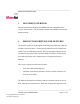
___________________________________________________________________________ Infrastructure Installation Guide Figure 1 All weather omni antenna Figure 2 Indoor office omni antenna Figure 3 Flat panel directional antenna Figure 4 Optional high gain antenna ___________________________________________________________________________ 11 Location Sensor Installation Guide Copyright WhereNet, Corp.
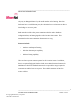
___________________________________________________________________________ Infrastructure Installation Guide Figure 5 Power supply Figure 6 Outdoor P.S.
___________________________________________________________________________ Infrastructure Installation Guide Figure 7 5 RJ cable tool Figure 8 Fluke LAN CableMeter CONFIGURATION The Location Sensor (Location Access Point) must be configured prior to operation. Configuration includes: • Setting the Location Sensor configuration, including the IP address • Setting the embedded Access Point configuration (LAP-4200 only), including the Service Set Identifier (ESS ID), and IP address.
___________________________________________________________________________ Infrastructure Installation Guide Both of these units are configured using: • LPManager software via Ethernet (preferred), • Telnet via Ethernet, or • Hyperterminal (or any terminal emulation software) via serial port For the LAP-4200, both the Location Sensor and the embedded Access Point must be independently configured. That is, both units must have their IP addresses correctly specified.
___________________________________________________________________________ Infrastructure Installation Guide document where indicated, and place one or more of the large type, six character labels on the exterior of the Location Sensor in positions that are visible after installation.
___________________________________________________________________________ Infrastructure Installation Guide The Location Sensors can be configured using either an automatic process or a manual process: Automatic Configuration TBD Manual Configuration • Connect to the Location Sensor using LP Manager, Telnet or Hyperterminal. • Confirm the unique MAC address for the Location Sensor. • Select Set IP Address from the menu and set the IP address.
___________________________________________________________________________ Infrastructure Installation Guide 6 ASSEMBLY INSTRUCTIONS The Outdoor Omni antenna must be mounted to the Location Sensor housing; the Indoor Office Omni antenna and the Flat Panel Directional antennas are mounted separately to the appropriate wall or ceiling. Follow the specific instructions included with the antennas. ____________ The left and right antenna must be correctly oriented per the site design.
___________________________________________________________________________ Infrastructure Installation Guide This equipment complies with Part 15 of the FCC Rules. Operation is subject to the following two conditions: 1. This device may not cause harmful interference. 2. This device must accept any interference received, including interference that may cause undesired operation.
___________________________________________________________________________ Infrastructure Installation Guide • Connect the equipment into an outlet on a circuit different from that to which the receiver is connected. • Consult the dealer or an experienced radio/ television technician for assistance. _____________ To comply with FCC RF exposure requirements, no one may remain within 20 cm of the antenna.
___________________________________________________________________________ Infrastructure Installation Guide The Location Sensor can be mounted to a wall using the integral keyhole mounting slots. An attachment hole is also provided to accept a 3/8 in (10 mm) threaded rod. A pole mount hardware kit is available separately. 8.1 Wall Mount The Location Sensor may be mounted directly against a non-metallic wall using the standard AK-210 All Weather Omni-directional antennas.
___________________________________________________________________________ Infrastructure Installation Guide 7.88 in 200.2 mm 9.22 in 234.2 mm Figure 10 Wall mounting hole dimensions _____________ If the Location Sensor is in a position in which it could be ripped off the wall by industrial equipment, it should be secured to the building infrastructure _____________ with a safety cable through the 3/8 inch (10 mm) hole in the housing.
___________________________________________________________________________ Infrastructure Installation Guide 8.2 3/8ths Threaded Rod The Location Sensor can be hung via a 3/8 inch (10 mm) threaded rod per the following instructions. The required supports, threaded rod, nuts, etc., are not included. • Cut the threaded rod to the desired length and install it directly above the desired Location Sensor position. • Thread one nut up 2 inches (50 mm) from the bottom of the threaded rod.
___________________________________________________________________________ Infrastructure Installation Guide 9 CABLING Figure 11 below shows the connections which must be made to the Location Sensor in normal operation. The connector types and recommended cable types are detailed in section 4 above. Power Ethernet Left Right Timing Antenna Serial Figure 11 Location Sensor connections 9.1 Power The customer must provide 120 Vac power to the specified Location Sensor position.
___________________________________________________________________________ Infrastructure Installation Guide This allows a 9 foot (3 m) “service loop” margin if the Location Sensor position must be readjusted after the AC power is installed. _____________ For outdoor installations the power supply must be installed within a suitable waterproof housing. Follow local and national building codes. _____________ 9.
___________________________________________________________________________ Infrastructure Installation Guide The following rules must be applied when connecting timing cables between the Location Sensors: • Do not connect the timing cable from one Location Sensor back to the same Location Sensor. • Do not connect two timing cables between the same two Location Sensors. • The maximum timing cable length is 1000 feet (310 m).
___________________________________________________________________________ Infrastructure Installation Guide ____________ Do not exceed the maximum Ethernet cabling length of 328 ft (100 m). ______________ 9.4 Access Point Antenna Cabling (Optional) In many installations, the Access Point antenna must have omni directional RF coverage to support communication from nearby 802.11 wireless terminals. Thus, in the standard configuration the Access Point shares the same antennas as the Location Sensor.
___________________________________________________________________________ Infrastructure Installation Guide ____________ The use of the optional high gain Access Point antenna will reduce the wireless LAN coverage range for hand held terminals in areas of the site to the side of and behind the high gain antenna due to the directivity of the ______________ antenna.
___________________________________________________________________________ Infrastructure Installation Guide q Location Sensor mounted within +/-1 foot (0.3 m) of position specified in Site Design document. After measuring the installed position, documenting it on the following form, and comparing it to the position specified in the Site Design document, the Account Manager should place an “X” in the installed position accepted/rejected line for each Location Sensor on site.
___________________________________________________________________________ Infrastructure Installation Guide LS Site Design ID Number Reference point desc. (e.g., column E12) Accept 2. Distance and bearing from reference point in X direction Distance and bearing from reference point in Y direction Height above floor level Z/ Direction LEDs are facing Reject installed position specified above MAC address: IP address: Specified in Site Design Actual installed Accept 3.
___________________________________________________________________________ Infrastructure Installation Guide LS Site Design ID Number Reference point desc. (e.g., column E12) Accept 6. Distance and bearing from reference point in X direction Distance and bearing from reference point in Y direction Height above floor level Z/ Direction LEDs are facing Reject installed position specified above MAC address: IP address: Specified in Site Design Actual installed Accept 7.
___________________________________________________________________________ Infrastructure Installation Guide LS Site Design ID Number Reference point desc. (e.g., column E12) Accept 10. Distance and bearing from reference point in X direction Distance and bearing from reference point in Y direction Height above floor level Z/ Direction LEDs are facing Reject installed position specified above MAC address: IP address: Specified in Site Design Actual installed Accept 11.
___________________________________________________________________________ Infrastructure Installation Guide LS Site Design ID Number Reference point desc. (e.g., column E12) Accept 14.
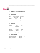
___________________________________________________________________________ Infrastructure Installation Guide Location Sensor Power/ Health WLAN Tag Reception Ethernet Outdoor Omni Antenna Figure 12 Location Sensor LED indicatorsLED indicators q Verify that each Location Sensor is operational by verifying that the left Power/ Health LED is illuminated green. q For wired 802.3 Location Sensors, verify that the Ethernet LED is blinking green. q Verify that the RX detects LED is blinking green.
___________________________________________________________________________ Infrastructure Installation Guide q Confirm that the site LS channel assignment is correct by running “display locate” from the LP Manager tool with a tag placed directly under each LS. Verify that the nearest LS, as indicated by a “0” in the display locate report, is that LS nearest the tag.