Rhein Tech Laboratories, Inc. 360 Herndon Parkway Suite 1400 Herndon, VA 20170 http://www.rheintech.com Appendix K: Client: FCC: IC: FCC ID: Model: Zebra Technologies Part 15.247 RSS-210 I28MD-ZLAN11G ZLAN11G Radio Module Manual Please see the following pages, particularly page 45 of the attached user manual.
UMAN-QLS-002 rev.
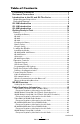
Table of Contents Proprietary Statements .............................................................. 5 Document Conventions .............................................................. 7 Introduction to the QL and QL Plus Series ............................... 8 Unpacking and Inspection ............................................................... 8 Reporting Damage ........................................................................... 8 QL 220 Introduction .....................................
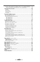
Compact Flash (802.11b) and Bluetooth Co-located Radio Modules ...... 47 European Regulatory Information for Co-located Radios ..................... 47 Using the Accessories ............................................................... 49 Belt Clip ....................................................................................................... 49 Desk Stand.................................................................................................. 51 Carrying Strap ..........................
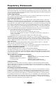
Proprietary Statements This manual contains proprietary information of Zebra Technologies Corporation. It is intended solely for the information and use of parties operating and maintaining the equipment described herein. Such proprietary information may not be used, reproduced, or disclosed to any other parties for any other purpose without the expressed written permission of Zebra Technologies Corporation.
Copyrights The copyrights in this manual and the label print engine described therein are owned by Zebra Technologies Corporation. Unauthorized reproduction of this manual or the software in the label print engine may result in imprisonment of up to one year and fines of up to $10,000 (17 U.S.C.506). Copyright violators may be subject to civil liability. This product may contain ZPL®, ZPL II®, and ZebraLink tm programs; Element Energy Equalizer ® Circuit; E3®; and AGFA fonts. Software © ZIH Corp.
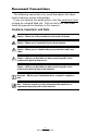
Document Conventions The following conventions are used throughout this document to convey certain information: If you are viewing this guide online, click the underlined text to jump to a related Web site. Click on italic text (not underlined) to jump to that location in this manual.. Cautions, Important, and Note Caution • Warns you of the potential for electrostatic discharge. Caution • Warns you of a potential electric shock situation.
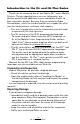
Introduction to the QL and QL Plus Series Thank you for choosing one of our Zebra® QL™ series Mobile Printers. These rugged printers are sure to become productive and efficient additions to your workplace thanks to their innovative design. Because they are made by Zebra Technologies, you’re assured of world-class support for all of your bar code printers, software, and supplies. • This user’s guide gives you the information you will need to operate all QL series printers.
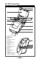
QL 220 Introduction Figure 1: QL 220 Overview 1 2 12 11 3 10 9 4 8 5 6 7 1 2. 3. 4. 5. 6. 7. 8. 9. 10. 11. 12. 13. 14. 15. 16. 17.
QL 320 Introduction Figure 1B: QL 320 Overview 1 2 12 3 17 4 16 5 11 6 10 7 9 8 1 2. 3. 4. 5. 6. 7. 8. 9. 10. 11. 12. 13. 14. 15. 16. 17.
QL 420 Introduction Figure 1C: QL 420 Overview 1 3 2 3 12 4 13 12 5 6 7 11 8 9 10 1 2. 3. 4. 5. 6. 7. 8. 9. 10. 11. 12. 13. 14. 15. 16. 17. 18. 19.
Getting Ready to Print Battery Installing the Battery Important • Batteries are shipped partially charged. Remove protective shrink-wrap and labels from new battery packs prior to use. 1. Rotate the Belt Clip to allow access to the Battery compartment. 2. Insert the battery into the printer as shown in Figure 2, 3. Rock the Battery into the printer as shown until it locks in place.
Figure 3: Single Charger LI72 Charger Charger Jack charge cycles when first put into service. Charging the Battery Model LI72 Single Battery Charger Refer to Figure 3. Your battery charger may look slightly different from the one illustrated. 1. Install the battery in the printer and plug the Charger into the appropriate A.C. wall receptacle. Then insert the charge cable into the battery charger jack. 2.
Model UCLI72-4 Quad Charger The UCLI72-4 Quad Charger is designed to charge up to four QL series battery packs simultaneously. Batteries must be removed from the printer to be charged in the Quad Charger. 1. Ensure that the charger has been installed properly per the Quad Charger instruction manual. Ensure that the power indicator on the front panel is on. 2. Remove any protective shrink-wrap and labels from all battery packs prior to use.
less time to reach their charged state. Batteries which have reached 80% of their charge capacity may be used, however, it is recommended that you allow the batteries to reach a full charge to maintain maximum battery life. The UCLI72-4 Quad Charger has a safety feature which stops charging a battery after six hours regardless of its charge state. Figure 4: Quad Charger Power Supply 1. Slide Battery Pack into Charger bay 2.
Battery Safety Caution • Avoid accidental short circuiting of any battery. Allowing battery terminals to contact conductive material will create a short circuit which could cause burns and other injuries or could start a fire. Important • Always dispose of used batteries properly. Refer to Appendix D for more battery recycling information. Caution • Use of any charger not approved specifically by Zebra for use with its batteries could cause damage to the battery pack or the printer and will void the warranty.
Loading the Media You can operate QL series printers in one of two different modes: Tear-Off or Peel-Off. Tear-Off mode allows you to tear off each label (or a strip of labels) after it is printed. In Peel-Off mode, the backing material is peeled away from the label as it is printed. After you remove this label, the next one is printed. Installing the Media QL 420 and QL 220 Printers 1. Open the printer: Refer to Figure 5 (QL 420 shown).
QL 320 Printers 1A. Open the printer: Refer to Figure 5a. • Rotate the latch release levers on each side of the printer as shown at “1” below. The latch assembly will flip open automatically as shown at “2”. • Rotate the Media Cover back as shown at “3”, exposing the media compartment and the adjustable media supports.
All models 2. Load the media: Loading media from an internal supply. Refer to Figure 6. • Grasp the media supports where shown and pull them apart. Insert the roll of media between them, and let the media supports close. Ensure that the media pulls off the core in the direction shown in Figure 6. The supports will adjust themselves to the width of the media, and the media should be able to spin freely on the supports. Figure 6: Installing Media Media Roll Note direction media pulls off the roll.
QL 420 Printers Only 2A. Load the media (continued): Loading media from an external supply. Refer to Figure 7. The QL 420 has a loading slot in the rear of the media compartment which allows you to use standard 4” (101.6 mm) wide fan-fold media from an external supply. The external supply must be designed such that it does not exert excessive drag as media is fed through the printer, which could result in distorted printing.
3. Close the Media Cover: Refer to Figure 8. • If you plan to use the printer in the tear-off mode, close the media cover as shown at “2”, then rotate the latch assembly as shown until it locks into place, as shown at “4”. • If you plan to use the printer in the peel-off mode, peel a few labels off of the media and pull it out of the printer as shown at “1”. Close the media cover as shown at “2”.
Operator Controls QL series printers are available with one of two possible control panels. The standard control panel is detailed below and in Figure 9. The optional control panel (Figure 10) features an LCD which allows easy display and selection of many printer functions detailed on following pages. Standard Keypad The standard keypad has three control buttons and two multipurpose indicators. • The Power Button turns the printer on and off.
• Printers with a wireless QuickLink module installed: a rapidly blinking LED indicates normal data transmission. • A steadily lit yellow LED indicates an error condition. This can be caused by one of the following: 1. The media cover is not completely closed and latched. 2. The printer is out of media. Figure 9: Standard Control Panel Yellow LED Steady Light indicates error condition: out of media or media cover not closed.
LCD Control Panel The optional LCD control panel has buttons for the power on/off and media feed functions just as in the standard control panel. In addition, it has two keys which allow easy navigation and selection of menu options affecting many printer functions. The “Scroll” button allows scrolling through the various options and settings. The “Select” button allows selection of the option or function displayed on the screen.
Indicates that the printer is receiving or transmitting data via a Bluetooth connection. A flashing icon indicates data transmission. This icon is functional only on printers with the Bluetooth wireless option installed. Printers with earlier firmware versions may not use this icon and will display the icon instead. (See below) Indicates that the printer is connected to a radio network via the 802.11 protocol. It remains on steadily with an 802.11 connection.
Function Extended LCD Functions Default setting Sensor Type Bar Baud Rate 19200 Data Bits 8 WLAN ID* Label Top Factory Set Value 000 Left Position 000 LCD Contrast 0 No-activity Timeout* 60 sec. Tear-off Position 00 Media Type Label Media Width Sensing† Off LCD Backlight Off Factory Reset (Resets all to factory set values) No Scroll & Select Options • • • • • • • Bar Gap 9600 19200 32400 7 8 N/A • Increase (+120 dots max.) • Decrease (-120 dots max.) • Increase (+120 dots max.
Verify the Printer Is Working Before you connect the printer to your computer or portable data terminal, make sure that the printer is in proper working order. You can do this by printing a configuration label using the “two key reset” method. If you can’t get this label to print, refer to “Troubleshooting”. Printing a Configuration Label 1. Turn the printer off. Load the media compartment with journal media (media with no black bars printed on the back) 2. Press and hold the Feed Button. 3.
• By means of a wireless LAN (Local Area Network) per 802.11b specifications. Cable Communication Caution • The printer should be turned off before connecting or disconnecting the communications cable. All QL series printers can communicate by cable; the specific cable supplied with your printer will vary with the host terminal and your model printer. RS-232C Communications The 8- pin circular connector on your communications cable plugs into the serial communications port on the side of the printer.
try to force the cable if it does not plug in. The other end of the cable must be plugged into the host terminal as shown in Figure 11, or to a serial or USB port on a computer (Figure 12.) The QL Plus series is configured with the USB Open HCI interface driver allowing it to communicate with Windows® based devices. USB drivers are included in the Zebra Universal Driver which can be downloaded from the Zebra Web site.
If you have a printer equipped with the Kickstand option, you must first remove the belt clip retainer as shown in Figure 14, retaining the two screws holding the retainer to the lower cover. Arrange the communications cable in a broad loop as detailed above, and capture it in the strain relief feature on the bottom of the belt clip retainer. Then re-secure the belt clip retainer to the bottom cover of the printer.
IR Communications Printers equipped for infrared (IR) communications are identified by a small “IR” logo on the unit’s label. (IR functions are disabled if a communications cable is used.) Printers with the IR option conform to the IrDA communications protocol. Ensure that there is a direct line of sight between the printer and the terminal that will be sending data. The IR window on the front of the printer must face the corresponding window on the terminal to properly send and receive signals.
Wireless Communications with Bluetooth™ “Bluetooth” is a worldwide standard for the exchange of data between two devices via radio frequencies. Bluetooth radios are relatively low powered to help prevent interference with other devices running at similar radio frequencies. This limits the range of a Bluetooth device to about 10 meters (32 feet). Both the printer and the device it communicates with must follow the Bluetooth standard.
WLAN Overview All QL series printers can be equipped with radios using the industry standard 802.11 protocols. QL series printers will have the FCC I.D. number of the radio on the product label. QL Plus series printers will have the FCC ID number on the serial number label on the back of the unit. • QL Wireless Network Printers with the CF module can be identified by the text “Wireless Network Printer” and FCC ID: I28MD-QL4137 on the front of the unit.
ers will vary with each LAN application. General information on establishing WLAN communications can be found in either the ”CPCL Programmers Manual” or the “Quick Start Guide for Mobile Wireless Printers” both available on-line. More information and LAN configuration utilities are included in Zebra’s Label Vista™ program (version 2.8 and later). Label Vista may be downloaded from the Zebra Web site.
Radio Regulatory Information Zebra Bluetooth Radios ZBR3 and QL+ZBR3 Caution • Exposure to Radio Frequency Radiation. The radiated output power of this internal Bluetooth radio is far below the FCC radio frequency exposure limits. The internal Bluetooth radio operates within guidelines found in radio frequency safety standards and recommendations. Do not use the printer in an unauthorized manner.
WLAN Module Using 802.11b CF Radio (North America) The following section only applies when the CF (Compact Flash) WLAN module (With FCC ID: I28MD-RW4137) is installed in a QL series printer (note that only one of the radio options can be installed in the printer at one time).
WLAN Module Using 802.11b CF Radio (Asia & EU Countries) The following section only applies when the CF (Compact Flash) WLAN module (With FCC ID: H9PLA4137) is installed in a QL series printer. Other than conditions specified elsewhere in this manual, only one of the radio options can be installed in the printer at one time and the antenna used for these transmitters must not be co-located or must not operate in conjunction with any other antenna.
Europe – EU Declaration of Conformity This device complies with the essential requirements of the R&TTE Directive 1999/5/EC. The following test methods have been applied in order to prove presumption of compliance with the R&TTE Directive 1999/5/EC: • EN55022:1998 European Immunity Standard • EN 60950: 2000 Safety of Information Technology Equipment • EN 300 328-2 V1.6.1 (2004-11) Technical requirements for spread-spectrum radio equipment • EN 301 489-1/-17 V1.5.1/1.2.1 (2003-12) -17 v1.2.
Zebra 802.11b WLAN Radio Module The following section only applies when the Zebra 802.11b WLAN radio module (With FCC ID: I28MD-ZLAN11B) is installed in a QL series printer (note that only one of the radio options can be installed in the printer at one time).
Europe – EU Declaration of Conformity This device complies with the essential requirements of the R&TTE Directive 1999/5/EC. The following test methods have been applied in order to prove presumption of compliance with the R&TTE Directive 1999/5/EC: • EN55022:1998 European Immunity Standard • EN 60950: 2000 Safety of Information Technology Equipment • EN 300 328-2 V1.6.1 (2004-11) Technical requirements for spread-spectrum radio equipment • EN 301 489-1/-17 V1.5.1/1.2.1 (2003-12) -17 v1.2.
QL 320 WLAN Module Using PCMCIA Radio The following section only applies when the PCMCIA WLAN module (FCC ID: I28-QL320352) is installed in the QL 320 printer (note that only one of the radio options can be installed in the printer at one time). The antenna used for this transmitter must not be co-located or must not operate in conjunction with any other antenna. The FCC ID number label is on the front of the QL 320. On all models the text can be read with the radio module installed.
Europe – EU Declaration of Conformity This device complies with the essential requirements of the R&TTE Directive 1999/5/EC. The following test methods have been applied in order to prove presumption of compliance with the R&TTE Directive 1999/5/EC: • EN55022:1998 European Immunity Standard • EN 60950: 2000 Safety of Information Technology Equipment • EN 300 328-2 V1.2.1 (2001-12) Technical requirements for spread-spectrum radio equipment • EN 301 489-17 V1.2.
QL 420 WLAN Module Using PCMCIA Radio The following section only applies when the PCMCIA WLAN module (FCC ID: I28-QL420352) is installed in the QL 420 printer. (Note that only one of the radio options can be installed in the printer at one time). The antenna used for this transmitter must not be co-located or must not operate in conjunction with any other antenna. The FCC ID number label is on the label on the front of the QL 420. On all models the text can be read with the radio module installed.
Europe EU Declaration of Conformity This device complies with the essential requirements of the R&TTE Directive 1999/5/EC. The following test methods have been applied in order to prove presumption of compliance with the R&TTE Directive 1999/5/EC: • EN55022:1998 European Immunity Standard • EN 60950: 2000 Safety of Information Technology Equipment • EN 300 328-2 V1.3.1 (2001-12)- Technical requirements for spreadspectrum radio equipment • EN 301 489-17 V1.2.
WLAN Module Using 802.11g Radio The following section only applies when the 802.11g WLAN module (With FCC ID: I28MD-ZLAN11G) is installed in a QL Plus series printer (note that only one of the radio options can be installed in the printer at one time). Other than conditions specified elsewhere in this manual, only one of the radio options can be installed in the printer at one time and the antenna used for these transmitters must not be co-located or must not operate in conjunction with any other antenna.
Europe – EU Declaration of Conformity This device complies with the essential requirements of the R&TTE Directive 1999/5/EC. The following test methods have been applied in order to prove presumption of compliance with the R&TTE Directive 1999/5/EC: • EN55022:1998 European Immunity Standard • EN 60950: 2000 Safety of Information Technology Equipment • EN 300 328-2 V1.2.1 (2001-12) Technical requirements for spread-spectrum radio equipment • EN 301 489-17 V1.2.