AP 7181 Access Point Installation Guide Version 1.0.0.
Contents 1 Introduction . . . . . . . . . . . . . . . . . . . . . . . . . . . . . . . . . . . 1 1.1 Document Conventions . . . . . . . . . . . . . . . . . . . . . . . . . . . 1 2 Hardware Installation. . . . . . . . . . . . . . . . . . . . . . . . . . . . 2 2.1 Precautions . . . . . . . . . . . . . . . . . . . . . . . . . . . . . . . . . . . . . 2 2.2 Deployment Guidelines . . . . . . . . . . . . . . . . . . . . . . . . . . . 3 2.3 Installation Methodology . . . . . . . . . . . . . . . . . . . . . . . . .
2.10 Mounting an AP 7181 . . . . . . . . . . . . . . . . . . . . . . . . . . . . 9 2.10.1 Pole Mounted Installations. . . . . . . . . . . . . . . . . . . . . . 10 2.11 Installing an AP 7181 . . . . . . . . . . . . . . . . . . . . . . . . . . . 10 2.11.1 Required Tools . . . . . . . . . . . . . . . . . . . . . . . . . . . . . . . 10 2.11.2 AP 7181 Connections and Ports. . . . . . . . . . . . . . . . . . 11 2.11.3 LED Status Indicator Panel . . . . . . . . . . . . . . . . . . . . . 14 2.11.
4 Regulatory Compliance . . . . . . . . . . . . . . . . . . . . . . . . . . . 85 4.1 Health and Safety Recommendations . . . . . . . . . . . . . . . 85 4.1.1 Warnings for the Use of Wireless Devices . . . . . . . . . . 85 4.1.2 Potentially Hazardous Atmospheres . . . . . . . . . . . . . . . 85 4.1.3 Reducing RF Exposure - Use Properly . . . . . . . . . . . . . 85 4.2 Power Supply . . . . . . . . . . . . . . . . . . . . . . . . . . . . . . . . . . 85 4.3 FCC Regulatory Information . . . . . . . . . . . . . .
MOTOROLA and the Stylized M Logo are registered in the US Patent & Trademark Office. All other product or service names are the property of their respective owners. © Motorola, Inc. 2010. All rights reserved.
Introduction 1 Introduction The purpose of this document is to provide installation and setup procedures for Motorola’s AP 7181 Access Point. The AP 7181 is a wireless broadband data system that uses mesh networking technology to support wide-area broadband data coverage. The system offers both 2.4 GHz 802.11b/g/n and 5.x GHz 802.11n Wi-Fi client access with 2.4 GHz 802.11 b/g/n and 5.x GHz 802.11a/ n meshing.
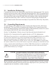
2 AP 7181 Access Point: Installation Guide 2 Hardware Installation An AP 7181 access point installation includes mounting the access point, connecting the access point to the network, and applying power. Installation procedures vary for different environments. 2.1 Precautions Before installing an AP 7181 model access point verify the following: Become familiar with grounding requirements (see Grounding Requirements). Verify the environment has a continuous temperature range between -40° C to 55° C.
Hardware Installation • • • • 2.2 Take precautions to avoid injury from falling tools and equipment. Crews should wear hardhats in and around the installation work site. Be aware of vehicular traffic in and around the installation work site. Do not hold any component containing a radio such that the antenna is very close to or touching any exposed parts of the body, especially the face or eyes, while transmitting.
4 AP 7181 Access Point: Installation Guide 2.3 Installation Methodology Consideration of the order in which units are installed when deploying an AP 7181 wireless network can work to ensure a more stable and functional network. The PTP backhaul layer should be deployed first. Next deploy all nodes for the PMP Access Point distribution layer. Next deploy Root nodes along with PMP Subscriber Modules (SMs) such that backhaul and network connectivity can be verified or corrected.
Hardware Installation 2.5 Minimum Installation Requirements The minimum requirements for installing an AP 7181: • • • • • • 2.6 AP 7181 Access Point Power Cable (Flying Leads) Standard Ethernet cable Yoke (attached) 22 mm Socket and driver to remove port caps #6 metric Allen Wrench to remove the Yoke (if a top mounted installation is required) Package Contents Check the package contents for the AP 7181.
6 AP 7181 Access Point: Installation Guide 2.7.2 Root Node Placement When planning for Root Node placement: • • • • • • • • 2.7.3 Identify Root node wireless backhaul technology (Point-to-Point (PTP), Point-toMultipoint (PMP)). Identify Ethernet or fiber optic backhaul. Identify Root node locations. Obtain all required permits and/or lease agreements. Verify that power is available at each potential node deployment location.
Hardware Installation • • Ensure that nodes are placed at the same height. Build the network outward from each root node, from least to greatest number of hops. As with Root nodes, it should be noted that it is incumbent upon the customer to obtain the required Pole Attachment Agreements for devices to be installed on traffic / utility poles. Obtaining the agreements can be a lengthy process, so ample lead time must be allowed.
8 AP 7181 Access Point: Installation Guide Always consider these general guidelines for device deployment height: • • • 2.8 Maintain a typical deployment height of 30 to 35 feet. For optimum performance, ensure that devices are oriented to have LoS to all neighboring devices. Locate Root Nodes which support Wireless Backhaul so that they have LoS to Backhaul clusters or PTP locations, such as towers.
Hardware Installation ! CAUTION Never plug a power cable wired to a power source for an AC unit into a DC unit. If the units will be plugged directly into an electircal wall outlet, power plug adapters are available for North America, Europe, and Australia. ! CAUTION Do not use the connector on the power cables for interrupting current. Never actively plug or unplug the connector while the cable is energized. 2.10 Mounting an AP 7181 The AP 7181 is designed for outdoor installations.
10 AP 7181 Access Point: Installation Guide 2.10.1 Pole Mounted Installations The optional Wall Gooseneck can also be used with the Pole Adapter for pole mounting. The Wall Gooseneck dimensions are 10x12x6 inches and it weighs 4 pounds. The Pole Adapter dimensions are 4x2.62x7 inches and it weighs 3 pounds. The Gooseneck attaches to the Yoke, which can be attached to the top or the bottom of the AP 7181.
Hardware Installation • • • • • 2.11.2 Torque Screwdriver - for the Sun Shields Torque Wrench Adjustable Wrench Standard Level Tube of Lithium Grease AP 7181 Connections and Ports The power cable and grounding connections, power indicator light, Ethernet and reset ports, and LED Status Panel on the bottom the AP 7181 are shown in the figure below.
12 AP 7181 Access Point: Installation Guide The Horizontal (HP) and Vertical (VP) connectors for the antenna cables are loacted on the top of the AP 7181. All Radome antenna panel cables are labeled as HP or VP. Attach each cable to the corresponding connector when performing a Remote Panel Antenna Installation or any other procedure which requires attaching antenna cables to the connectors.
Hardware Installation WARNING! ! CAUTION When disconnecting the antenna cables from the unit or removing an antenna panel and replacing it with a Blank panel, terminators MUST be placed on the unused horizontal and vertical connectors on the top of the unit. It is also recommended that the antenna cable connectors and terminators on the horizontal and vertical connectors on the top of the AP 7181 be wrapped with both mastic tape and electrical tape.
14 AP 7181 Access Point: Installation Guide 2.11.3 LED Status Indicator Panel There are six LEDs on the AP 7181 which are visible on the bottom of the unit through light pipes.The LEDs have the following display characteristics and functionality: LED 1 Blinking Red indicates booting. Solid Red defines a failure condition. White defines normal operation LED 2 LED 3 LED 4 - 5 GHz LED 5 - 2.4 GHz Emerald Amber Green Green defines 2.
Hardware Installation 2.11.4 ! Removing the AP 7181 Kit from the Shipping Carton CAUTION WARNING! Never lift an AP 7181 using the Radome antenna panels or other plastic parts. Always lift the unit by the Yoke or metal antenna rings. An AP 7181 weighs 39 pounds. Use all appropriate cautions when lifting and consider a two man lift when necessary. 1. Open the shipping carton and remove top packaging material.
16 AP 7181 Access Point: Installation Guide 2. Remove the accessories pack from the shipping carton.
Hardware Installation 3. Open the plastic bag covering the unit. 4. Roll the plastic bag to the bottom of the shipping carton and using the Yoke or Antenna Ring, carefully remove the unit from the box . Using this method will help prevent damage to the antenna assembly. 2.11.5 Staging the Device Prior to Installation WARNING! An AP 7181 weighs 39 pounds. Use all appropriate cautions when lifting and consider a two man lift when necessary. 1. Place on solid surface with the Yoke facing up.
18 AP 7181 Access Point: Installation Guide 3. To gain access to the Ethernet and or console ports you will need to remove the protective caps. A 22 mm socket will be required to remove the Ethernet port caps covering Gigabit Ethernet ports GE1 and GE2. A 19 mm socket is required to remove the console port cap (if required). 4. Using the 22 mm socket remove the port caps for Gigabit Ethernet GE1 and GE2. 5. Remove the cap on the cable gland as shown below.
Hardware Installation 6. Carefully hand tighten the gland into Gigabit port GE1. Once the gland is snug, use a 24 mm socket and finishing tighten the gland. If the node is going to be configured as a Mesh Point Root node (Mesh Point Root nodes have a direct wired Ethernet connection to the core network or an Ethernet connection to a wireless backhaul) a cable gland will be required for Gigabit Ethernet port GE1.
20 AP 7181 Access Point: Installation Guide If the Mesh Point Root node is also going to have an external device attached (e.g. surveillance camera) an additional cable gland will be required for Gigabit Ethernet port GE2 (make sure the WAN port GE2 has been configured to permit an attached external device during the configuration process). NOTE The AP 7181 supports 802.
Hardware Installation If the device being staged is a Mesh Point node (no wired connection to the core network) and no external device is going to be attached then no cable glands are required. If the Mesh Point node is going to have an external device attached (e.g. surveillance camera) a cable gland is required for Gigabit Ethernet port GE1.
22 AP 7181 Access Point: Installation Guide 7. Repeat the process if a second cable gland is required. 8. Attach an Ethernet cable to Gigabit Ethernet port GE2 (to be used with an external laptop for configuring the unit). You will also need to terminate the flying lead power cable with the proper plug (for the country of operation) so the unit can be powered for configuration. After preparing the power cable attach the cable to the power port. Notice that the power connector is keyed.
Hardware Installation 9. After the unit has been configured, if the GE2 port is not going to be used to attach an external device to the AP7181, reattach the port cap. If the GE2 port is going to be used to attach and external device, attach the cable gland to the GE2 port. 10. Reattach the Yoke. 11. Return the unit to the shipping carton for transport to the installation site.
24 AP 7181 Access Point: Installation Guide 2.12 ! • • • • Field Installation CAUTION Only trained and qualified personnel should install this equipment. Only a licensed electrician should install power cable / energize circuits. All device wiring must follow the National Electric Code (NEC) or wiring requirements in the country of installation. All location building and structure codes must be observed. Ensure that the power source for the AP 7181 is de-energized prior to installation.
Hardware Installation 2.12.1 Bottom Mount Installation The pole mount adapter (Part Number RLN6197A) will accommodate a banding strap up to 1¼ inch width. Banding straps and the banding tool are not included when ordering the pole mount adapter. The pole mount adapter can be mounted to poles 3 inches to 15 inches in diameter and has a load rating of 75 lbs. 1. Attach the pole mount adapter (or other mounting bracket hardware) to the mounting asset and ensure that the mounting bracket is level. 2.
26 AP 7181 Access Point: Installation Guide NOTE Apply lithium grease to the threads of the Gooseneck. This will help prevent corrosion from occurring and facilitate removal of the Yoke if the unit needs to be serviced. 3. Carefully remove the unit from the shipping carton. 4. Place on a solid surface with the Yoke facing up. 5. Carefully lift device and align the Yoke with the Gooseneck. In the picture below two professional installers in a bucket truck are lifting the unit onto the Gooseneck.
Hardware Installation 6. Attach the Yoke to the Gooseneck by rotating the device clockwise for a minimum of four turns. Ensure that the device is level. 7. The two set screws can now be inserted to increase stability. Tighten the set screws to between 214.2 and 250.0 inch pounds (lbf-in). 8. If the AP 7181 you are mounting is a Mesh Point Root node or a Mesh Point node with an external device (e.g. surveillance camera) perform the required Ethernet cabling.
28 AP 7181 Access Point: Installation Guide installation. It is recommended that an Outdoor- UV Rated, shielded cable is used in AP 7181 deployments. Some examples are: • Superior Essex 04-001-55 • Best-Tronics BT-0562 In most cases Ethernet cable will need to be custom cut to length. After preparing the Ethernet cable and attaching shielded RJ-45 end connectors feed the cable through the cable gland cap and rubber insert as shown below. 9. Insert data cable through cable gland (i.e.
Hardware Installation c. Using an adjustable wrench, tighten the cable grip until it fits snugly around the Ethernet cable. d. Repeat the process for additional Ethernet connections if required. ! • • • • CAUTION Only trained and qualified personnel should install this equipment. Only a licensed electrician should install power cable / energize circuits. All device wiring must follow the National Electric Code (NEC) or wiring requirements in the country of installation.
30 AP 7181 Access Point: Installation Guide The power cable included with the AP 7181 is a flying lead cable. Most installations will require the installer to install an additional power cable. The AP 7181 flying lead power cables are 12 feet long. The installer should splice the power cable to the AP 7181 flying lead cable in accordance to the National Electric Code (NEC) or wiring requirements in the country of operation. Only outdoor rated power cable should be used.
Hardware Installation 11. The unit must be grounded according to the Motorola R56 2005 Manual for Standards and Guidelines for Communication Sites. The grounding screw is shown below in green. 12. Secure and conceal the cables using UV resistant tie wraps. Tie wraps should be used to secure the cables along the Gooseneck.
32 AP 7181 Access Point: Installation Guide 13. If desired, attach the sun shields to the top/bottom using the captive screws. If attaching the sun shields to the bottom of the unit, first remove the knock out discs in the center to fit around the Yoke. Tighten the captive screws to between 39.9 and 53.1 inch pounds (lbf-in). 14. Once physical installation is completed the circuit powering the AP 7181 can be energized. Verify that the green power LED is lit and the unit is powered on.
Hardware Installation 2.12.2 Top Mount Installation 1. Carefully remove the unit from the shipping carton. 2. Place on a solid surface with the Yoke facing up. 3. Remove the Yoke and the Allen socket head screws from the bottom of the unit. The pole mount adapter (Part Number RLN6197A) will accommodate a banding strap up to 1¼ inch width. Banding straps and the banding tool are not included when ordering the pole mount adapter.
34 AP 7181 Access Point: Installation Guide 4. Attach the pole mount adapter (or other mounting bracket hardware) to the mounting asset and ensure that the mounting bracket is level. 5. Using the 4 hex head bolts (3/8"x16"x1") included with pole mount adapter (Part Number RLN6197A), secure the Gooseneck to the pole mount adapter. NOTE Apply lithium grease to the threads of the Gooseneck. This will help prevent corrosion from occurring and facilitate removal of the Yoke if the unit needs to be serviced.
Hardware Installation 6. Attach the Yoke to the Gooseneck by rotating the device counter clockwise for a minimum of four turns. WARNING! Carefully align the Yoke with the Mounting Bracket to avoid cross threading. 7. Ensure that the Yoke and the Mounting Bracket are level. 8. Loosely attach the Allen socket head screws to the top of the unit. Leave the screws loose enough to attach the Yoke. WARNING! An AP 7181 weighs 39 pounds.
36 AP 7181 Access Point: Installation Guide 9. Carefully lift the unit into position, aligning the key slots for the Yoke with the Allen socket head screws and slide the Yoke to the final position. ! CAUTION Ensure that the Allen socket hex screws are tight and in the locked position before releasing the full weight of the unit. 10. Torque the Allen socket head screws to between 108.7 and 145.0 Inch Pounds (lbfin). 11. The Set Screws can now be inserted to increase stability.
Hardware Installation 12. If the AP 7181 you are mounting is a Mesh Point Root node or a Mesh Point node with an external device (e.g. surveillance camera) perform the required Ethernet cabling. The Ethernet cable gland is optimized for cables of diameter .39 to .55 inches. Smaller diameter cables can achieve a watertight seal if the cable gland is properly tightened during installation. It is recommended that an Outdoor- UV Rated, shielded cable is used in AP 7181 deployments.
38 AP 7181 Access Point: Installation Guide c. Using an adjustable wrench, tighten the cable grip until it fits snugly around the Ethernet cable. d. Repeat the process for additional Ethernet connections if required. ! • • • • CAUTION Only trained and qualified personnel should install this equipment. Only a licensed electrician should install power cable / energize circuits. All device wiring must follow the National Electric Code (NEC) or wiring requirements in the country of installation.
Hardware Installation The power cable included with the AP 7181 is a flying lead cable. Most installations will require the installer to install an additional power cable. The AP 7181 flying lead power cables are 12 feet long. The installer should splice the power cable to the AP 7181 flying lead cable in accordance to the National Electric Code (NEC) or wiring requirements in the country of operation. Only outdoor rated power cable should be used.
40 AP 7181 Access Point: Installation Guide 15. The unit must be grounded according to the Motorola R56 2005 Manual for Standards and Guidelines for Communication Sites. The grounding screw is shown below in green.
Hardware Installation 16. Secure and conceal the cables using UV resistant tie wraps. Tie wraps should also be used to secure the cables along the Gooseneck. 17. If desired, attach the sun shields to the top/bottom using the captive screws. If attaching the sun shields to the bottom of the unit, first remove the knock out discs in the center to fit around the Yoke. Tighten the captive screws to between 39.9 and 53.1 inch pounds (lbf-in).
42 AP 7181 Access Point: Installation Guide 2.13 Remote Panel Antenna Installation When choosing a deployment location to optimize performance, it may be necessary to mount a device such that one of the antenna panels may be obstructed. For example, traffic light poles can completely obscure one of the panels in the AP 7181 antenna array. The Remote Panel antenna kit can be used to address this use case.
Hardware Installation When the Remote Panel antenna installation is used, a Blank antenna panel should be attached to cover the side of the device facing the obstruction. Using a Blank antenna panel will help protect the interior of the AP 7181. Blank antenna panels can also be used when a device is installed directly against a wall or the side of a building. See Installing the Blank Antenna Panel.
44 AP 7181 Access Point: Installation Guide WARNING! ! CAUTION When disconnecting the antenna cables from the unit or removing an antenna panel and replacing it with a Blank panel, terminators MUST be placed on the unused horizontal and vertical connectors on the top of the unit. It is also recommended that the antenna cable connectors and terminators on the horizontal and vertical connectors on the top of the AP 7181 be wrapped with both mastic tape and electrical tape.
Hardware Installation 2.13.1 Preparing the AP 7181 To prepare the AP 7181 for installation using the Remote Panel antenna: 1. Remove the screws for one of the four Radome antenna panels. 2. Grasp the lower part (barrel) of the antenna cable connector and carefully detach the antenna cables from the connectors on the device. Remove the Radome antenna panel.
46 AP 7181 Access Point: Installation Guide 3. Attach the extension cable for the Remote Antenna panel to the device. 4. Carefully route the extension cable inside the antenna rings on the device.
Hardware Installation 5. Using the four screws provided, attach a Blank antenna panel to the unit to cover the side of the device where the functional antenna panel was removed. 6. Return the unit to the shipping carton for transportation to the installation site. 7. Collect the Radome panel that was removed from the unit and all other hardware and tools required for the installation. 2.13.2 Installing the Remote Panel Antenna To complete the installation of the Remote Panel antenna at the site: 1.
48 AP 7181 Access Point: Installation Guide 4. Tighten the nuts on the mounting bracket so that the support arm remains in the desired position. 5. Use a cordless drill and a 3.6 mm bit to drill the hole for the set screw on the mounting bracket. 6. Insert and tighten the M4.8 set screw for the mounting bracket. 7. Using the supplied clamps, attach the Remote Antenna panel to the mounting bracket.
Hardware Installation ! CAUTION When adjusting the Remote Mount antenna panel on the mounting bracket, ensure that the mounting bracket does not extend past the top of the antenna panel to comply with wind loading requirements. 8. Complete the installation of the mouting bracket using the appropriate method for the installation requirements. 9. Attach the extension cable from the AP 7181 to the connectors on the Remote Mount antenna panel and wrap the connections with Mastic tape and Electrical tape.
50 AP 7181 Access Point: Installation Guide 10. Secure the cables to the mounting bracket using UV resistant tie wraps. 11.
Hardware Installation 2.13.3 Installing the Blank Antenna Panel In addition to Remote Panel antenna installations, Blank antenna panels can also be used if the unit is going to be placed directly against a wall or building. The Radome antenna should be removed and the Blank panel should be attached to side of the unit that will be facing any obstruction.
52 AP 7181 Access Point: Installation Guide WARNING! ! When disconnecting the antenna cables from the unit or removing an antenna panel and replacing it with a Blank panel, terminators MUST be placed on the unused horizontal and vertical connectors on the top of the unit. CAUTION It is also recommended that the antenna cable connectors and terminators on the horizontal and vertical connectors on the top of the AP 7181 be wrapped with both mastic tape and electrical tape.
Hardware Installation To install a Blank antenna panel: 1. Remove the screws for one of the four Radome antenna panels. 2. Grasp the lower part (barrel) of the antenna cable connector and carefully detach the antenna cables from the connectors on the device. Remove the Radome antenna panel.
54 AP 7181 Access Point: Installation Guide 3. Attach the terminators to the antenna cable connectors. 4. Wrap the terminators with mastic tape and electrical tape. 5. Using the four screws provided, attach a Blank antenna panel to the unit to cover the side of the device where the functional antenna panel was removed.
Getting Started 3 Getting Started Use the following procedures to configure and setup up the AP 7181. 3.1 Initially Connecting to the Access Point The AP 7181 can be staged and configured using one of several connection techniques. Managing the access point includes viewing network statistics and setting configuration options. The access point requires one of the following connection methods to manage the network: • • • Secure Java-Based WEB UI - (use Sun Microsystems JRE 1.
56 AP 7181 Access Point: Installation Guide 3.1.1 Connecting to the Access Point Using the WAN Port NOTE These procedures are only valid for initially connecting to an AP 7181. To initially connect to the access point using the access point's WAN port: 1. Connect AC power to the access point. 2. The WAN (or GE2) port default is configured with an IP address of 10.1.1.1. Configure a laptop with an IP address of 10.1.1.2 / 255.0.0.0 and connect to the GE2 port. 3.
Getting Started 3.1.2 Connecting to the Access Point Using the LAN Port To initially connect to the access point using the access point's LAN port: 1. The LAN (or GE1/POE) port default is set to DHCP. Connect the access point's GE1/POE port to an Ethernet segment with access to a DHCP server. The access point will automatically receive an IP address. 2.
58 AP 7181 Access Point: Installation Guide 9. Using a Web browser, use the access point's IP address to access the access point.
Getting Started 3.2 Basic Device Configuration For the basic setup described in this section, the Java-based Web UI will be used to configure the access point. Use the access point's LAN interface for establishing a link with the access point. Configure the access point as a DHCP client. For optimal screen resolution, set your screen resolution to 1024 x 768 pixels or greater. 1. Open a browser. If you used the WAN method, point your browser to 10.1.1.1.
60 AP 7181 Access Point: Installation Guide 2. Log in using admin as the default Username and motorola as the default Password. Use your new password if it has been updated from default. 3. If the default login is successful, the Change Admin Password window displays. Change the password. Enter the current password and a new admin password in fields provided. Click Apply. Once the admin password has been updated, a warning message displays stating the access point must be set to a country.
Getting Started 3.2.1 Configuring Device Settings Many of the most important parameter settings located on the configuration pages throughout the menu tree have been consolidated on the Quick Setup screen to facilitate getting the unit up and running quickly. Configure a set of minimum required device settings within the Quick Setup screen. When you change the settings in the Quick Setup screen, the values also change for other screens where these parameters are displayed.
62 AP 7181 Access Point: Installation Guide 3. Optionally enter the IP address of the server used to provide system time to the access point in the Time Server field. NOTE DNS names are not supported as a valid IP address. The user is required to enter a numerical IP address. Once the IP address is entered, the access point's Network Time Protocol (NTP) functionality is engaged automatically.
Getting Started To configure the IP Settings: 1. Click the LAN tab to set a minimum set of parameters to use the access point LAN interface. 2. Select the Enable LAN Interface checkbox to forward data traffic over the access point's LAN connection. The LAN connection is enabled by default. 3. Use the This interface drop-down menu to specify how network address information is defined over the access point's LAN connection.
64 AP 7181 Access Point: Installation Guide 7. If using the static or DHCP Server option, enter a Default Gateway to define the numerical IP address of a router the access point uses as a default gateway on the Ethernet. 8. If using the static or DHCP Server option, enter the Primary DNS Server numeric IP address. 9. If using the DHCP Server option, use the Address Assignment Range parameter to specify a range of addresses to be reserved for mapping clients to IP addresses.
Getting Started CAUTION ! NOTE Only a qualified wireless network administrator should set the access point radio configuration. Refer to Configuring the 802.11a/n or 802.11b/g/n Radio in the AP 7181 Product Reference Guide for an understanding of configurable radio values and their implications.. Even an access point with a minimal configuration must be protected against data theft and corruption. A security policy should be configured for WLAN1 as part of the basic configuration outlined in this guide.
66 AP 7181 Access Point: Installation Guide Removing the WAN Interface from GE2 By default, the WAN interface is enabled and has a static IP address of 10.1.1.1/8. This interface is tied to physical port GE2 and is used for initial configuration. In order to use GE2 to connect external devices such as an IP surveillance camera, you will need to configure the port from a WAN role to a LAN role.
Getting Started To remove the WAN interface from GE2: 1. Select Network Configuration -> WAN from the menu tree. 2. In the Role drop-down box, select LAN. For more information on WAN port configuration options, refer to Configuring WAN Settings in the AP 7181 Access Point Product Reference Guide.
68 AP 7181 Access Point: Installation Guide The following diagram illustrates the configuration changes that result from setting the Role parameter to LAN. GE1 GE2 LAN1 Bridge WAN DHCP Default Configuration 10.1. 1.
Getting Started 3.2.2 Configuring WLAN Security Settings By default the AP 7181 has a default security policy of No Security. In the following example a WPA2/CCMP security policy will be configured that can be applied to newly created WLANs. To configure a basic security policy for a WLAN: NOTE Even an access point with minimal configuration values must be protected against data theft and corruption.
70 AP 7181 Access Point: Installation Guide 3. Select the WPA2/CCMP (802.11i) radio button. The WPA2/CCMP Settings field is displayed within the New Security Policy screen. 4. Configure the WPA2/CCMP Settings fields as required to define the Pass Key used to generate the WEP keys. Key Settings Click the ASCII Passphrase box and enter a passphrase 8 to 63 characters long. Mixed Mode Under WPA2-CCMP Mixed Mode select the Allow WPA/ WPA2-TKIP clients checkbox to enable support for TKIP and AES encryption.
Getting Started 3.2.3 Creating a Secure Recovery WLAN When staging an AP 7181, it is recommended to create a security recovery WLAN to be used in case the unit becomes unreachable due to errors in configuration or fluctuating conditions which affect transmission across the wireless network. This is particularly important if your AP 7181 is addressed via DHCP as the IP address would be lost if a node became stranded.
72 AP 7181 Access Point: Installation Guide 2. Determine what ESSID (or network name) to use. It is recommended that a unique ESSID be used for each AP 7181. Since the recovery WLAN is going to be on the 2.4 GHz radio, we chose to use the MAC address of the 2.4 GHz radio. This can be found by selecting Radio1 [802.11b/g/n] located under Network Configuration Wireless - Radio Configuration. The radio MAC address is located in the properties window. Record this MAC address.
Getting Started 3. Create a non-broadcasting secure WLAN. Select Network Configuration -> Wireless . Click Create.
74 AP 7181 Access Point: Installation Guide 4. Enter an ESSID. use the MAC address recorded in the previous step.Under Available On select the 802.11 b/g/n checkbox.
Getting Started 5. Select the Security Policy you previously created for WPA2/CCMP. Sele the Use Secure Beacon checkbox to suppress the broadcasting of this network. 6. Click Apply. 7. To map the secure WLAN to LAN2, select Network Configuration -> LAN. Click WLAN Mapping.
76 AP 7181 Access Point: Installation Guide 8. In LAN/VLAN/WLAN Mapping, find the ESSID you created and use the dropdown box under LAN and select LAN2. Click OK. 9. The LAN Configuration screen will be displayed again. Click Apply. 10. The secure recovery WLAN is now configured. Record the ESSID for future reference.
Getting Started 3.2.4 Testing Connectivity Verify the access point's link with an MU by sending ping packets to the associated MU. Use the Echo Test screen to specify a target MU and configure the parameters of the test. Connect an MU to the hidden recovery WLAN and configure its IP address for DHCP. NOTE Before testing for connectivity, the target MU needs to be set to the same ESSID as the access point.
78 AP 7181 Access Point: Installation Guide ratio of packets sent to the number of packets received to determine the link quality between the MU and the access point. 6. Click OK to exit the Echo Test screen and return to the MU Stats Summary screen. 3.2.5 Creating a Mesh Point In order for AP 7181s to mesh using MeshConnex, a Mesh Point must be created on each access point. Once created, mesh points can be applied to either radio (or both).
Getting Started To create a Mesh Point: 1. Select Network Configuration -> Wireless -> Radio Configuration -> Radio1 (or Radio2). Confirm that the Channel Selection parameter in the Channel, power and Rates Settings field is set to Automatic.
80 AP 7181 Access Point: Installation Guide 2. Select Network Configuration -> MeshConnex and click Create.
Getting Started 7. The New Mesh Point dialog is displayed. Enter a Mesh ID (case-sensitive). This Mesh ID must be the same on all AP 7181 devices. Next select a radio to mesh on by selecting the appropriate box under Available On. If this AP 7181 will be connected to the wired network (Root node / Gateway node) select the Is Root checkbox. 8. Click Apply to save your settings.
82 AP 7181 Access Point: Installation Guide 9. The Mesh Point you created will be displayed in the MeshConnex Configuration window. Highlight the Mesh Point and click Enable. 10. Repeat the process for each device you are staging.
Getting Started 11. To verify that a Mesh has been established, select Status & Statistics -> MeshConnex Stats and click on the name of the desired Mesh Point. 12. Select the Neighbor tab. In this example, only one neighbor is displayed. NOTE A neighboring device will not be displayed in the table on the Neighbor tab if only a single device has been configured. Another Non-Root device must have already been created and the devices must be interconnected.
84 AP 7181 Access Point: Installation Guide 13. Select the Path tab to see if a route exists for each neighbor. The Path State should indicate Valid and the Bind State should indicate Bound. 3.3 Where to Go from Here? Once basic connectivity has been verified, the access point can be fully configured to meet the needs of the network and the users it supports. Refer to the AP 7181 Product Reference Guide for detailed information on AP 7181 devices in wireless networks.
Regulatory Compliance 4 Regulatory Compliance All Motorola devices are designed to be compliant with rules and regulations applicable to the locations where they are sold and will be labeled as required. Any changes or modifications to Motorola equipment, not expressly approved by Motorola, could void the user's authority to operate the equipment. Motorola's devices are professionally installed. The Radio Frequency Output Power will not exceed the maximum allowable limit for the country of operation. 4.
86 AP 7181 Access Point: Installation Guide 4.3 FCC Regulatory Information This device complies with Part 15 of the FCC Rules. Operation is subject to the following two conditions: (1) this device may not cause harmful interference, and (2) this device must accept any interference received; including interference that may cause undesired operation. This equipment has been tested and found to comply with the limits for a Class B digital device, pursuant to Part 15 of the FCC rules.
Customer Support 5 Customer Support If you have read this document and made every effort to resolve installation or operation issues yourself and still require support, please contact your regional Motorola support representatives or visit the Motorola Mesh Networks web site at: http://motorola.wirelessbroadbandsupport.com/support/mesh/contact.
88 AP 7181 Access Point: Installation Guide
MOTOROLA INC 1303 E. ALGONQUIN ROAD SCHAUMBURG, IL 60196 http://www.motorola.com Version 1.0.0.