
Installation Guide


AP 7181 Access Point: Installation Guide
14
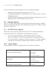
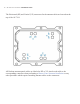
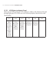
2.11.3 LED Status Indicator Panel
There are six LEDs on the AP 7181 which are visible on the bottom of the unit
through light pipes.The LEDs have the following display characteristics and
functionality:
LED 1 LED 2 LED 3
LED 4 - 5
GHz
LED 5 - 2.4
GHz LED 6
Blinking
Red
indicates
booting.
Solid Red
defines a
failure
condition.
White
defines
normal
operation
Green
defines
normal GE1
operation.
Yellow
defines a
collision
Green
defines
normal GE2
operation.
Yellow
defines a
collision
Amber
defines 5
GHz radio as
configured.
Emerald
defines 2.4
GHz radio as
configured.
Not used